1
Parking Cooler
BlueCool Truck
With Tundra Inverter
Shore Power Installation Supplement
–
–
–
–
–
2/2012
Improper installation or repair of Webasto heating and cooling systems can cause
fire or the leakage of deadly carbon monoxide leading to serious injury or death.
Installation and repair of Webasto heating and cooling systems requires special
Webasto training, technical information, special tools and special equipment.
NEVER attempt to install or repair a Webasto heating or cooling system unless
you have successfully completed the factory training course and have the
technical skills, technical information, tools and equipment required to properly
complete the necessary procedures.
ALWAYS carefully follow Webasto installation and repair instructions and heed all
WARNINGS.
Webasto rejects any liability for problems and damage caused by the system
being installed by untrained personnel.
BCT010818A
Table of Contents
Overview...............................................................................................................................................................4
How It Works:....................................................................................................................................................4
Shore Power Layout: ............................................................................................................................................5
Shore Power Box Fuse Layout: ........................................................................................................................5
Installation:............................................................................................................................................................6
Electrical Harness Routing................................................................................................................................6
Inverter Connections .........................................................................................................................................6
Schematics ...........................................................................................................................................................8
Verify System Operation.......................................................................................................................................9
Troubleshooting ................................................................................................................................................. 10
Malfunctions during system “Shore Power” ................................................................................................... 11
Malfunctions during system “Charge Mode” .................................................................................................. 14
Malfunctions during system “Discharge Mode”.............................................................................................. 18
Category: BlueCool Truck
Shore Power Installation
Document Number: "#4!
$ATE
Description: Optional Shore Power Installation
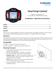
Overview
Shore Power is a term used by the marine and RV industries to describe the power available from
land-based sources that boats and recreational vehicles hook-up to in order to run on-board
appliances and HVAC. This power is usually provided at a pedestal at each boat slip or RV lot. This
available shore power allows the vehicle / vessel to run “hotel loads” without running an engine.
The Shore Power System is an important component of the Webasto no-idle solution. The system
delivers power to run “hotel loads” for the comfort and convenience of the drivers. Virtually any
6!#DEVICEFROMLAPTOPSTOMICROWAVESCOULDBEUSEDWHILEPArked at truck stops, rest areas or
even at warehouses and depots that provide shore power receptacles. The system is designed to
connect directly to land based power with a FOOT%XTENSION#ORDRATEDFORUPTOAMPS 6OLTSGAUGEWIRING
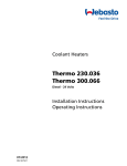
How It Works:
7HENPLUGGEDTOANYCONVENTIONALPLUGOUTLETLANDBASEDPOWER6!#THESYSTEMAUTOMATICALLY
detects connection to the Shore Power and switches the system into the Shore Power mode. When in
Shore Power mode battery charger is turned ON (batteRYISCHARGEDIFNEEDEDAND6!#IS
AVAILABLEATRECEPTACLETORUNhHOTELLOADv4HISAPPLIESONLYWHENTHETRUCKISATRESTNOTMOVING
!FTERMINCONTROLUNITWILLSTARTTHECHARGECYCLEOFTHE"#4UNITIFNEEDEDBASEDONTHE
temperature inside the storage core. Power used to run compressor is used from land based power
ANDFORTHERESTOFTHE"#4SYSTEMCONTROLLERcondenser fan, coolant pump and fans in the air
HANDLERDIRECTLYFROMTHEBATTERY Controller will allow the user to operate unit in discharge mode at
the same time the unit is charging. The unit can run in charge/discharge mode as long as connected
to tHE3HORE0OWERLANDBASEDPOWER6!#
Fig 1.
Webasto Product N.A., Inc. s.ORTH2OADs&ENTON-ICHIGAN
For Technical Assistance in USA Call: -sIn Canada Call: -
Visit us on the Web at: www.webasto.us
Page of Shore Power Installation
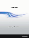
Shore Power Layout:
&OLLOWTHEWIRINGDIAGRAMBELOWTHE3HORE0OWERSYSTEMISPLUGANDPLAYANDSHOULDEASILYCONNECT
ASSHOWNBELOW-AKESURETODISCONNECTSYSTEMPOWERFROMTHEVEHICLEPRIORTOINtegrating shore
power into the system.
Fig 2.
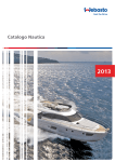
Shore Power Box Fuse Layout:
Fig 3.
Webasto Product N.A., Inc. s.ORTH2OADs&ENTON-ICHIGAN
For Technical Assistance in USA Call: -sIn Canada Call: -
Visit us on the Web at: www.webasto.us
Page of Shore Power Installation
Installation:
4OBEGINTHISINSTALLATIONTHEPHYSICALMOUNTINGOFTHESHOREPOWERBOXCHARGINGUNIT6OLT!#
RECEPTACLE (OTEL ,OAD AND THE FLANGED SURFACe receptacle (shore power land based power input
PLUG MUST BE PERFORMED Plan your harness routing according to the components that must be
reached, such as the batteries, air handler, power inverter, etc. Ensure a safe and secure means of
routing and attachment along frame members and cross members. Also consider the point at which
the harness will enter the vehicle’s sleeper compartment.
NOTE: &IG assumes the harnesses will be routed from under the bunk, through a hole in the floor
of the sleeper and into the left storage compartment. This compartment will house hardware such
as the power inverter, DC charger, and Shore Power "OX. Your particular application may not follow
this example; however the harness and battery cables are of sufficient length to allow for different
routing possibilities.
CAUTION: Always make sure that no harnesses are mounted to any moving parts and that anything
routed between the frame and the body of the vehicle has ample slack for movement.
Electrical Harness Routing
Plan your harness routing according to the components that must be reached, such as the batteries,
air handler, power inverter, charger, etc. Ensure a safe and secure means of routing and attachment
along frame members and cross members. Also consider the point at which the harness will enter
the vehicle’s sleeper compartment. REFERTOSECTIONOFTHE"#4)NSTALLATION-ANUAL"#4C
for further routing detail.
NOTE: 7HEN ROUTING "#4 !# HARNESS BEGIN AT THE 3TORAGE Core and work forward. This will
prevent the harness from being too short when the final connections are made in the cab of the
vehicle.
NOTE: When routing both the AC and DC harnesses, make sure that they are separated and routed
individually to eliminate noise on the temperature sensor circuit.
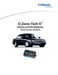
Inverter Connections
Ensure all power has been turned off to the system. Install the
Shore Power box near the power inverter allowing ample room for
the harness connections. Refer to section OF THE "#4
)NSTALLATION -ANUAL ("#4C FOR ADDITIONAL MOUNTING
INSTRUCTIONS 3EE &IG ON PAGE of this manual for hardware
location examples. -OUNT THE SUPPLIED Shore Power charging unit
in close proximity of the power inverter.
Two Pin Connector at Inverter
Shore
Power
Box
Inverter
Fig 4.
The connections between the Shore Power box, the charger, and
the inverter are all plug and play and are labeled accordingly on the
Shore Power box. -AKE SURE TO Connect the two pin connector
between the DC harness (black loom and the power inverter as
shown in fig. .
NOTE: Ensure the inverter and charger are properly grounded to
THE CHASSIS OF THE VEHICLE 2EFER TO SECTION OF THE "#4
installation manual for additional information.
Fig 5.
Plug in the pin connector of the DC harness BLACKLOOM to the
"#4(ARNESS&IG Webasto Product N.A., Inc. s.ORTH2OADs&ENTON-ICHIGAN
For Technical Assistance in USA Call: -sIn Canada Call: -
Visit us on the Web at: www.webasto.us
Page of Shore Power Installation
Install the supplied protective bootS &IG ON BOTH THe positive
and negative cables and wire loom where necessary.
NOTE: Some modification to boots may be required to fit over dual
cable connections).
Fig 6.
(A) Connect one end of the positive and negative cables to the DC
output terminals of the Iota charger. Route and connect the other
end to the DC Input studs on the power inverter. (Picture does not
REPRESENTCORRECTGAUGECABLEWIRE
TUNDRA INVERTER
NOTE: Do not tighten the nuts on the input inverter studs at this
time as additional connections are needed.
A
A
B
B
Fig 7.
Cover studs with protective boots
(B) Connect one end of the supplied positive and negative DC
cables directly to the DC input studs on the inverter and tighten
nuts. Connect the other ends to the battery bank as described in
SECTION OF THE "#4 )NSTALLATION -ANUAL "#4#
0ICTUREDOESNOTREPRESENTCORRECTGAUGECABLEWIRE
CAUTION: Keep power inverter studs from turning while tightening
nuts!
NOTE: Make sure to pull protective boot over studs after nuts have
been tightened and install a zip tie around each base.
Fig 8.
Fig 9.
Locate an acceptable area to mount the exterior flanged surface
receptacle. Ensure there is nothing that interferes behind the
designated location and drill a hMMHOLE #AREFULLY INSERT
and mount the flanged surface receptacle. Route the surface
receptacle harness to the shore power box connection labeled
“Shore Power”.
NOTE: Install the supplied sticker label near the Shore Power Plug
and ensure it is in a visible location.
Fig 10.
Webasto Product N.A., Inc. s.ORTH2OADs&ENTON-ICHIGAN
For Technical Assistance in USA Call: -sIn Canada Call: -
Visit us on the Web at: www.webasto.us
Page of Shore Power Installation
Schematics
Webasto Product N.A., Inc. s.ORTH2OADs&ENTON-ICHIGAN
For Technical Assistance in USA Call: -sIn Canada Call: -
Visit us on the Web at: www.webasto.us
Page of Shore Power Installation
Verify System Operation
Perform a final visual inspection of electrical items to ensure ALL connections are completed and
secure.
2. #ONNECTA$IGITAL-ULTI--ETERTOTHEBATTERIESANDENSURE they are fully charged (desired voltage
should be at or GREATERTHAN6$##ONNECTABATTERYCHARGERTO batteries and recharge if
necessary.
Turn off battery charger and disconnect from batteries.
#HECKFUSESFUSESLOCATEDONTHE3HORE0OWERBOXA main system fuse at the batteries,
AND!INVERTERFUSEATTHEBATTERIES
#HECKIFTHECIRCUITBREAKER#"ISINTHEh/.vPOSITION
#HECKIFTHEINVERTERSWITCHISINh/.v)POSITION
Check Storage Core internal temperature. If temperature is lower THAN°&THESYSTEMISALREADY
CHARGEDANDITWILLNOTBEGINANOTHERCHARGECYCLEUNTILTHETEMPERATURERISESABOVE°&
#HECKIFAMBIENTTEMPERATUREISGREATERTHAN°&)FTEMPERATUREISLOWERTHAN°&- °&THE
system will not charge.
Turn vehicle engine on and verify that green LED on inverter is illuminated, if not refer to
-ALFUNCTIONSDURINGSYSTEM“#HARGE-ODE” section for the diagnosis.
!FTERHOURHASELAPSED the A/C compressor and the condenser fan will begin operation.
NOTE: If the compressor fails to start, check the LED indicator on the power inverter. If it has
changed to orange, turn inverter OFF and allow batteries to recharge for a short period of
time. Ensure ALL battery connections are clean and tight.
Run the refrigeration UNITFORMINUTESMINIMUMCYCLE or longer before switching the ignition
key off.
NOTE: To determine if the system is chilling properly, the condenser fan will be pushing air
that is several degrees above ambient temperature. Also, the refrigeration lines at the
expansion valve will begin to cool down and over time, become frosty.
12. Facing the air handler, the left control knob (A) controls system activation and the fan speed. By turning the
knob clockwise, the system is activated. A green LED (B) will illuminate indicating the system is active.
Turning the knob further clockwise increases the fan speed accordingly.
13. The right control knob (C) controls cooling performance. By turning the knob clockwise, the coolant
circulating pump begins operation. Turning the knob further clockwise increases cooling performance.
NOTE: If the interior cab temperature is lower than 68°F the coolant pump will not run and
chilled air will not be felt coming from the wall mounted air handler.
Webasto Product N.A., Inc. s.ORTH2OADs&ENTON-ICHIGAN
For Technical Assistance in USA Call: -sIn Canada Call: -
Visit us on the Web at: www.webasto.us
Page of Shore Power Installation
Troubleshooting
In the event of a "LUE#OOL4RUCKSYSTEMmalfunction (equipped with Shore PowerCheck / verify the
following points before continuing to troubleshooting trees:
x
x
x
x
x
x
x
Visually check wiring connections at the batteries, inverter, charger, Shore Power box, the
PCCU (ParkinG#OOLER#ONTROL5NITANDcharge unit.
Check for blown fuses, fuses located on the Shore Power box, !MAINSYSTEM fuse at the
batteries, and !INVERTERfuse at the batteries
#HECKIFTHECIRCUITBREAKER#"ISINthe “ON” position.
Check if the inverter switch is in “ON” )POSITION
#HECK3TORAGE#OREINTERNALTEMPERATURE)FTEMPERATUREISLOWERTHAN°&the system is
already charged and it will not begin another charge cycle until the temperature rises above
°&
Check if ambient temperature is GREATERTHAN°&)FTEMPERATUREISLOWERTHAN °&- °&
the system will not charge.
Turn vehicle engine on and verify that green LED on inverter is illuminated, if not refer to
-ALFUNCTIONSDURINGSYSTEM“#HARGE-ODE” section for the diagnosis.
Note: During all BCT system testing where it asks to check pin continuity at the PCCU 10way connector; do not disconnect the connector. Doing so will result in the system delay
timer to reset and all testing will be delayed 30 minutes until timer has completed its cycle .
Refer to the diagram below regarding REFERENCESTOTHE3HORE0OWER-way connector throughout
the troubleshooting section.
3HORE0OWER-way connector pin layout
Pin
A
"
C
D
E
&
G
H
J
K
Description
6$#BATTERY
6$#BATTERY
Ground battery
6$#0##5POWERINPUT
6$#h)GNITION/.vINPUT
6$#0##5OUTPUTh#HARGE-ODE/.v
6$#0##5INPUTh#HARGE-ODE/.v
6$#CONDENSERFAN
Not used
Not used
Webasto Product N.A., Inc. s.ORTH2OADs&ENTON-ICHIGAN
For Technical Assistance in USA Call: -sIn Canada Call: -
Visit us on the Web at: www.webasto.us
Page of Shore Power Installation
Malfunctions during system “Shore Power”
Additional checks before troubleshooting:
x
x
x
Verify voltage output is APPROXIMATELY6!#ATTHEEXTERNALPOWERGRID
-AKESURETHEREISNOADDITIONALLOADS connected to the same power grid. This could trip the
circuit breaker during the compressor start.
Disconnect any “Hotel Load” inside the vehicle that might be connected to the INTERIOR'&#)
plug.
Webasto Product N.A., Inc. s.ORTH2OADs&ENTON-ICHIGAN
For Technical Assistance in USA Call: -sIn Canada Call: -
Visit us on the Web at: www.webasto.us
Page of Shore Power Installation
NO
Shore Power Operation (Page 1 of 2)
YES
Connect System to an external
power grid (Shore Power)
Unplug the connector labeled Shore
Power at the Shore Power Box.
Is there 120VAC available at
connector? (harness side)
Is there 120VAC at the external
power grid?
Find working power grid.
Check cable/connections between
external power grid and Shore
Power box. Repair or replace as
necessary.
Plug the connector labeled "Shore
Power" back into the Shore Power
box.
Is there 120VAC available at "Hotel
Load" plug (GFCI)?
Unplug the connector labeled
"Hotel Load" at the Shore Power
box.
Is there120VAC available at
connector? (Shore Power box side)
Is the circuit breaker in the
"ON" position?
Reset circuit breaker.
Replace defective Shore
Power box.
Is there 12VDC between positive
and negative posts of charger?
Note: Charger output voltage
should be close to 13.4VDC.
Check GFCI plug functionality per
manufacturer instructions.
Replace defective GFCI
plug.
Unplug the connector labeled
"Charger" at the Shore Power Box.
Is there 120VAC available at
connector? (Shore Power box side)
Replace defective Shore
Power box.
Replace defective charger.
Unplug the connector labeled
"Compressor" at the Shore Power
Box.
Is there120VAC available at
connector? (Shore Power box
side)
Note: There is a 30 minute time
delay built into the PCCU (Parking
Cooler Control Unit).
Check 30A fuse at main battery
connection? Is fuse good?
Inspect circuit for short and
replace defective fuse.
Check fuse F4 (2A) located at the
Shore Power box. Is fuse good?
Inspect circuit for short and
replace defective fuse.
Check fuse F1 (2A) at Shore
Power box. Is fuse good?
Inspect circuit for short and
replace defective fuse.
Check fuse F2 (10A) at Shore
Power box. Is fuse good?
Inspect circuit for short and
replace defective fuse.
Is there 12VDC between pin 1
and pin 2 of the PCCU connector?
Repair wiring connections
as necessary.
Continue on page 2
Plug the connector labeled
"Compressor" at the Shore Power
Box. Does compressor turn on?
Refer to Charge Mode
troubleshooting section for
compressor diagnosis.
Shore Power Charge mode
functional. Check discharge mode
for proper operation when
connected to Shore Power, refer to
the Discharge Mode
Troubleshooting section. Is
Discharge Mode functional?
Refer to Discharge Mode
troubleshooting section for
diagnosis.
Shore Power System performing
according to specification.
Webasto Product N.A., Inc. s.ORTH2OADs&ENTON-ICHIGAN
For Technical Assistance in USA Call: -sIn Canada Call: -
Visit us on the Web at: www.webasto.us
Page of Shore Power Installation
NO
Shore Power Operation (Page 2 of 2)
YES
From page 1
Is the 12VDC available at pin G of
the 10-way connector?
Replace defective Shore Power
box.
Is 12VDC available at pin 3 at the
PCCU connector?
Check wiring and connections.
Repair as necessary.
Check if 12VDC available at pin F
of 10 way connector.
Unplug storage core sensor
connector at the storage core.
Use Webasto test tool
(BCT010249A) to identify sensor
functionality. Is there a
temperature reading?
Check wiring connections and
repair as necessary. If all
connections are good and no
temperature reading is present,
replace the defective temperature
sensor.
Check storage core temperature.
If > 30 degrees F.
If lower than 30 degrees F,
storage core is charged.
Is there continuity across
terminals of the refrigerant
pressure switch? (located in
charge unit box).
Check refrigerant pressure.
(Switch will be normally open if
pressure < 29 PSI or > 326 PSI).
If pressure is between 29 and
326 PSI and switch is open;
replace defective pressure switch.
Is there continuity across terminals
of the ambient temperature switch?
(located in charge unit box).
Is ambient temperature lower than
60 degrees F? (Switch will be
normally open if temperature is
lower than 55 +/- 5 degrees).
Note: If any power interruptions
occurred during testing, the 30
minute time delay will re-start.
Replace defective ambient
temperature switch.
Move vehicle to location where
ambient temperature is > than 60
degrees F. In a situation where
this is not possible, to force
charge mode for testing purposes
only, disconnect ambient
temperature sensor and jump two
pins together. Note: Bypassing
ambient temperature sensor will
not diagnosis a faulty sensor itself.
Is there 12VDC at pin 5 of the
PCCU?
Replace defective PCCU.
Is there 12VDC at pin F of the 10way connector?
Repair or replace wiring harness.
Replace the Shore Power Box
Webasto Product N.A., Inc. s.ORTH2OADs&ENTON-ICHIGAN
For Technical Assistance in USA Call: -sIn Canada Call: -
Visit us on the Web at: www.webasto.us
Page of Shore Power Installation
Malfunctions during system “Charge Mode”
The PCCU has a built in delay time operation feature. The engine must run for MINUTES or the
system must be plugged into an external POWERGRIDUSINGONLYTHE7EBASTOSUPPLIEDFTEXTENSION
cord (P/N: !before system will begin charge mode operation.
Additional checks before troubleshooting:
x
x
Check continuity across terminals of the ambient temperature switch located at the charge
UNIT)FTHEREISNOCONTINUITYANDAMBIENTTEMPERATUREISGREATERTHAN°&REPLACETHE
defective temperature switch.
Check continuity across terminals of the pressure switch located at the charge unit. The
sWITCHWILLNORMALLYOPENFORPRESSURELOWERTHAN 03)ANDGREATERTHAN03). If open
and pressure MEASUREDISBETWEENAND03) replace the defective pressure switch.
Webasto Product N.A., Inc. s.ORTH2OADs&ENTON-ICHIGAN
For Technical Assistance in USA Call: -sIn Canada Call: -
Visit us on the Web at: www.webasto.us
Page of Shore Power Installation
NO
Charge Mode (Page 1 of 3)
YES
Engine "ON" 30
minutes.
Compressor on?
Condenser fan on?
Condenser fan on?
If system is not
performing to the
specification, consult
manufacturing
facility.
Check fuse F3 (20A) located at
the Shore Power box. Is it
good?
Inspect circuit for short and
replace defective fuse.
Check fuse F3 (20A) located
at the Shore Power box. Is it
good?
Inspect circuit for short and
replace defective fuse.
Is there 12VDC at pin H of the
10-way connector?
Replace Shore Power box.
Is there 12VDC at the
condenser fan connector?
(harness side)
Repair wiring connections as
necessary.
Check wiring connections at
condenser fan. Is connection
ok?
Repair wiring connections as
necessary.
Replace defective condenser
fan.
Unplug connector labeled
"Compressor" at the Shore
Power box.
Is there 120VAC at connector
(Shore Power box side)
Check for 120VAC at compressor
between C and R posts. Is
120VAC present?
Refer to section 6.4 to further
diagnose compressor. Replace as
necessary.
Continue to page 2.
Check connections at the
compressor posts. Are
connections ok?
Check AC harness
connections and capacitor(s).
Refer to service manual
section 6.4 to check
capacitors.
Repair wiring connections as
necessary.
Repair wiring or replace entire
harness with capacitors.
Webasto Product N.A., Inc. s.ORTH2OADs&ENTON-ICHIGAN
For Technical Assistance in USA Call: -sIn Canada Call: -
Visit us on the Web at: www.webasto.us
Page of Shore Power Installation
NO
Charge Mode (Page 2 of 3)
YES
From Page 1
Power Inverter Green
LED illuminated?
Is switch in ON (I) position?
Turn switch ON (I).
Is there a 12VDC ignition signal
at pin E of 10-way connector?
Check ignition source, wiring and
connections and repair as
necessary.
Check 2-way connector between
inverter and Shore Power box for
continuity? (Shore Power box side)
Replace defective Shore Power
box.
Check 250A fuse. Is fuse good?
Inspect circuit for short and
replace defective fuse.
Is there12VDC between positive
and negative posts of inverter?
Check wiring and connections
and repair as necessary
Power Inverter Green LED
illuminated?
Unplug inverter harness at
Shore Power box.
Is there 120VAC at
connector? (inverter side)
Plug inverter harness back
into the Shore Power box.
Is circuit breaker (F5) in
"ON" position? (Located on
the Shore Power box)
Replace defective inverter.
Turn circuit breaker (F5) to "ON"
position. Does it stay in the "ON"
position?
Check for 120VAC at compressor
between C and R posts. Is
120VAC present?
Refer to section 6.4 to further
diagnose compressor. Replace as
necessary.
Is12VDC available at Pin G
of the 10-way connector?
Continue to Page 3
Unplug the connector labeled
"Compressor" at the Shore Power
box.
Reset the the circuit breaker.
Does it stay in the "ON" position?
Replace defective Shore Power
box.
Is there 120VAC available at
"Compressor" connector? (Shore
Power box side)
Replace defective Shore Power
box.
Check connections at the
compressor posts. Are
connections ok?
Repair wiring connections as
necessary.
Check AC harness connections
and capacitor(s). Refer to service
manual section 6.4 to check
capacitors.
Repair wiring or replace entire
harness with capacitors.
Check 30A fuse at main battery
connection? Is fuse good?
Inspect circuit for short and
replace defective fuse.
Check fuse F1 (2A) at Shore
Power box. Is fuse good?
Inspect circuit for short and
replace defective fuse.
Check fuse F2 (10A) at Shore
Power box. Is fuse good?
Inspect circuit for short and
replace defective fuse.
Is there 12VDC between pin 1
and pin 2 of the PCCU
connector?
Repair wiring as necessary.
Replace defective PCCU
Webasto Product N.A., Inc. s.ORTH2OADs&ENTON-ICHIGAN
For Technical Assistance in USA Call: -sIn Canada Call: -
Visit us on the Web at: www.webasto.us
Page of Shore Power Installation
NO
Charge Mode (Page 3 of 3)
YES
From Page 2
Is12VDC available at pin 3 at
the PCCU connector?
Check if 12VDC available at
pin F of 10 way connector.
Note: If any power
interruptions occurred during
testing, the 30 minute time
delay will re-start.
Check wiring and connections.
Repair as necessary.
Unplug storage core sensor
connector at the storage core.
Use Webasto test tool
(BCT010249A) to identify sensor
functionality. Is there a
temperature reading?
Check wiring connections and
repair as necessary. If all
connections are good and no
temperature reading is present,
replace the defective temperature
sensor.
Check storage core temperature.
If > 30 degrees F.
If lower than 30 degrees F,
storage core is charged.
Is there continuity across
terminals of the refrigerant
pressure switch? (located in
charge unit box).
Check refrigerant pressure.
(Switch will be normally open if
pressure < 29 PSI or > 326 PSI).
If pressure is between 29 and
326 PSI and switch is open;
replace defective pressure switch.
Is there continuity across terminals
of the ambient temperature switch?
(located in charge unit box).
Is ambient temperature lower than
60 degrees F? (Switch will be
normally open if temperature is
lower than 55 +/- 5 degrees).
Replace defective ambient
temperature switch.
Move vehicle to location where
ambient temperature is > than 60
degrees F. In a situation where
this is not possible, to force
charge mode for testing purposes
only, disconnect ambient
temperature sensor and jump two
pins together. Note: Bypassing
ambient temperature sensor will
not diagnosis a faulty sensor itself.
Is there 12VDC at pin 5 of the
PCCU?
Replace defective PCCU.
Is there 12VDC at pin F of the 10way connector?
Repair or replace wiring harness.
Replace the Shore Power
Box
Webasto Product N.A., Inc. s.ORTH2OADs&ENTON-ICHIGAN
For Technical Assistance in USA Call: -sIn Canada Call: -
Visit us on the Web at: www.webasto.us
Page of Shore Power Installation
Malfunctions during system “Discharge Mode”
Additional check before troubleshooting:
x
Check the vehicles interior temperature. If it is lower tHAN°&THECOOLANTPUMPWILLNOTRUN
and chilled air will not be felt coming from the wall mounted air handler.
Webasto Product N.A., Inc. s.ORTH2OADs&ENTON-ICHIGAN
For Technical Assistance in USA Call: -sIn Canada Call: -
Visit us on the Web at: www.webasto.us
Page of Shore Power Installation
NO
Discharge Mode
YES
Turn discharge mode on (Fan
knob located on air handler).
Is Green LED Illimunated on
air handler?
Are four air handler fans
functioning properly?
Check 30A fuse located at the
battery connection. Is it good?
Inspect circuit for short and
replace defective fuse.
Check fuse F2 (10A) located at
the Shore Power box. Is it good?
Inspect circuit for short and
replace defective fuse.
Is there 12VDC at Pin D of the
10 way connector?
Repair wiring as necessary.
Is there 12VDC between pin 1
and pin 2 of the PCCU
connector?
Repair wiring as necessary.
Replace defective PCCU.
Turn temperature selector to
maximum cooling. (Located
on the air handler)
Check the coolant pump for
operation. Is it running?
Note: If temperature knob is
in the full counter clockwise
position or interior cab
temperature is lower than 68
degrees F the coolant pump
will not run.
Check for 12VDC on Pin 4 of the
PCCU. Is 12VDC present?
Replace defective PCCU.
Check for 12VDC at coolant pump
connector on harness side. Is
12VDC present?
Repair wiring as necessary
Check wiring connections at
coolant pump. Is connection ok?
Repair wiring as necessary
Replace defective coolant pump.
Is system cooling?
System is functioning
properly
Check the storage core state of
charge. Is the storage core
charged?
Check coolant loop for proper flow
and coolant level.
Charge system and repeat
discharge mode check.
Repair coolant loop as
necessary.
)F YOU HAVE ANY QUESTIONS ABOUT THIS BULLETIN PLEASE CONTACT OUR TECHNICAL SUPPORT TEAM AT -ORVIA email at info-US WEBASTOCOM.
Webasto Product N.A., Inc. s.ORTH2OADs&ENTON-ICHIGAN
For Technical Assistance in USA Call: -sIn Canada Call: -
Visit us on the Web at: www.webasto.us
Page of W ebasto Product N.A ., Inc.
15083 North Road
Fenton, MI 48430
Technical Assistance Hotline
USA: (800) 860-7866
Canada: (800) 667-8900
www.webasto.us
www.techwebasto.com