1
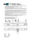
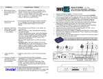
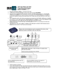
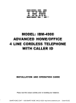
MODEL: IBM-412
ADVANCED HOME/OFFICE
4 LINE TELEPHONE
INSTALLATION AND OPERATION GUIDE
Please read this manual carefully 1prior to installing your telephone.
2
TABLE OF CONTENTS
FCC INFORMATION ................................................................................................................... 5
IMPORTANT SAFETY INSTRUCTIONS ................................................................................... 6
BATTERY CAUTIONARY INSTRUCTIONS ............................................................................. 7
GETTING STARTED .................................................................................................................... 8
Package Contents ....................................................................................................................... 8
Compatibility .............................................................................................................................. 8
LOCATION OF CONTROLS AND FEATURES ......................................................................... 9
Useful Features and Terms .......................................................................................................... 10
Lights and Cadence Reference List .............................................................................................. 11
INSTALLATION ........................................................................................................................... 12
Selecting a Location to Install Your Telephone .............................................................................. 12
Installing the Batteries ................................................................................................................. 12
Connecting Your Telephone Lines ............................................................................................... 12
Counter Top/Desk Top Installation ............................................................................................. 14
Wall Mounting ............................................................................................................................. 15
TELEPHONE OPERATIONS SETUP .......................................................................................... 17
List of System Defaults ................................................................................................................ 17
Assigning Extension Numbers ...................................................................................................... 17
Programming Tone or Pulse Mode .............................................................................................. 18
Programming Line Connection ON/OFF ..................................................................................... 18
Programming Ringer ON/OFF ..................................................................................................... 18
Adjusting Volume Levels .............................................................................................................. 19
BASIC OPERATIONS .................................................................................................................. 20
Making an Outgoing Call .............................................................................................................. 20
Using Speed Dial ......................................................................................................................... 20
Using Last Number Redial ........................................................................................................... 20
Using Auto Redial ........................................................................................................................ 21
Answering an Incoming Call ......................................................................................................... 21
Placing a Call on Hold .................................................................................................................. 21
3
HEADSET OPERATION .............................................................................................................. 22
Headset Enable/Disable ............................................................................................................... 22
Headset Assembly ....................................................................................................................... 22
Adjusting the Headset Volume ..................................................................................................... 22
Making an Outgoing Call Using the Headset ................................................................................ 23
Answering an Incoming Call ......................................................................................................... 23
INTERCOM ................................................................................................................................... 24
Direct Station Select (DSS) Keys .................................................................................................. 24
Placing an Intercom Call .............................................................................................................. 24
Answering an Intercom Call ........................................................................................................ 25
PAGING ........................................................................................................................................ 26
Paging a Specific Extension .......................................................................................................... 26
Receiving an Individual Page ......................................................................................................... 26
Answering an Individual Page ....................................................................................................... 26
Paging All Extensions ................................................................................................................... 26
Answering a Page to All Extensions .............................................................................................. 26
TELEPHONE FEATURES AND OPERATIONS ......................................................................... 27
Pause .......................................................................................................................................... 27
Flash ........................................................................................................................................... 27
Mute ........................................................................................................................................... 27
Tone ........................................................................................................................................... 27
Do Not Disturb (DND)................................................................................................................ 27
Line Privacy ................................................................................................................................. 28
Call Transfer ............................................................................................................................... 28
Speed Dialing .............................................................................................................................. 28
Conference Calling ...................................................................................................................... 30
Technical Specifications ............................................................................................................... 31
CARE AND MAINTENANCE ...................................................................................................... 32
TROUBLESHOOTING ................................................................................................................. 33
LIMITED WARRANTY STATEMENT ......................................................................................... 35
WALL MOUNTING TEMPLATE ................................................................................................. 36
4
FCC INFORMATION
Equipment Notes:
Your IBM-412 telephone is registered with the Federal Communications Commission and is in compliance
with Part 15J and Part 68 of the FCC Rules and Regulations. On the bottom of this equipment is a label indicating among other information, the FCC Registration Number and Ringer Equivalence Number (REN) for
the equipment. You must, upon request, provide this information to your telephone company. The REN is
useful to determine the number of devices you may connect to your telephone line and still have all devices
ring when your telephone number is called. In most cases (but not all areas), the sum of the REN’s of all the
devices connected to one line should not exceed (5) five. The IBM-412 telephone utilizes high sensitivity
ringer circuits which will function reliably with up to twelve telephones installed.
v The IBM-412 telephone cannot be used with coin service pay service telephones.
v The IBM-412 telephone cannot be connected to a party line service..
v The IBM-412 telephone is Hearing Aid Compatible.
If you experience trouble with this telephone equipment, disconnect it from the telephone network until the
problem has been corrected. The telephone company may discontinue service if the telephone is determined to cause harm to the telephone network. In this case, the telephone company will:
v If possible, notify the customer in advance that the service is being discontinued.
v Provide the customer with the opportunity to correct the situation.
v Inform the customer of their right to file a complaint with the FCC.
Your local telephone company may make changes in its facilities, equipment, operations or procedures that
could affect the proper functioning of your equipment. If they do, you will be notified in advance to give you
an opportunity to maintain uninterrupted telephone service.
Interference Information
This equipment generates, uses and can radiate low level radio frequency energy. It has been tested and
found to comply with the limits for a Class B digital device in accordance with the specifications in Part 15J of
the FCC Rules, which are designed to provide reasonable protection against such interference in a residential
installation. If this equipment does cause interference to radio or television reception, which can be determined by unplugging it from the telephone line. If the interference is caused by the IBM-412, the user is encouraged to try to correct the interference by one or more of the following measures:
v Reorient the radio or TV receiving antenna.
v Relocate this device with respect to the receiver.
v Move this device away from the receiver.
If necessary, the user should consult the dealer or an experienced radio/television technician for additional
suggestions. The user may find the following booklet, prepared by the Federal Communications Commission, helpful. This booklet is available from the U.S. Government printing Office. There may be a charge for
this booklet.
"How to Identify and Resolve Radio-TV Interference Problems"
U.S. Government Printing Office
Washington, D.C. 20402
Stock Number. 004-000-00345-4
5
IMPORTANT SAFETY INSTRUCTIONS
Before using your telephone equipment, basic safety precautions should always be followed to reduce the risk of
fire, electrical shock and injury to persons, including the following:
v Read and understand all instructions.
v Follow all warnings and instructions marked on the product.
v Unplug this product from the wall telephone jack and power outlet before cleaning. Do not use liquid cleaners
or aerosol cleaners. Use a damp cloth for cleaning.
v Do not use this product near water, for example, near a bathtub, wash bowl, sink or laundry tub.
v Do not place this product on an unstable cart, stand, or table. The product may fall, causing serious damage to
the product.
v This product should never be placed near or over a radiator or heat register.
v This product should be operated only from the type of power source indicated on the marking label.
v Do not allow anything to rest on the power cord. Do not locate this product where the cord will be walked on.
v Do not overload wall outlets and extension cords as this can result in the risk of fire or electric shock.
v Never push objects of any kind into this product through cabinet slots as they may touch dangerous voltage
points or cause shorts that could result in the risk of fire or electric shock.
v To reduce the risk of electric shock, do not disassemble this product. Take it to a qualified serviceman when
service or repair work is required. Opening or removing covers may expose you to dangerous voltages or other
risks. Incorrect re-assembly can cause electric shock when the appliance is subsequently used.
v Unplug this product from the wall outlet and refer servicing to qualified service personnel under the following
conditions:
v When the power supply cord or plug is damaged or frayed.
v If liquid has been spilled into the product.
v If the product has been exposed to rain or water.
v If the product does not operate normally by following the operating instructions. Adjust only those controls
that are covered by the operating instructions because improper adjustment of other controls may result in
damage.
v If the product has been dropped or cabinet has been damaged.
v If the product exhibits a distinct change in performance.
v Avoid using a telephone (other than a cordless type) during an electrical storm. There is risk of electric shock
from lightning.
v Do not use the telephone to report a gas leak in the vicinity of the leak.
SAVE THESE INSTRUCTIONS
6
BATTERY CAUTIONARY INSTRUCTIONS
BATTERIES: CAUTION
v Use only 1.5 volt, AA-size batteries, (15A) carbon-zinc or alkaline batteries. (batteries not included.)
v Do not dispose of the batteries in a fire. The cells may explode. Check with local codes for possible
special disposal instructions.
v Do not open or mutilate the batteries. Released electrolyte is corrosive and may cause damage to
the eyes or skin. It may be toxic if swallowed.
v Exercise care in handling batteries in order not to short the battery with conducting materials such
as rings, bracelets, and keys. The battery or conductor may overheat and cause burns.
v Do not attempt to recharge the batteries identified for use with this product. The batteries may leak
corrosive electrolyte or explode.
v Do not attempt to rejuvenate the batteries identified for use with this product by heating them. Sud-
den release of the battery electrolyte may occur causing burns or irritation to eyes or skin.
v When replacing batteries, all batteries should be replaced at the same time. Mixing fresh and dis-
charged batteries could increase internal cell pressure and rupture the discharged batteries.
v When inserting batteries into this product, the proper polarity or direction must be observed. Re-
verse insertion of batteries can cause charging, and that may result in leakage or explosion.
v Remove the batteries from this product if the product will not be used for a long period of time
(several months or more) since during this time the battery could leak in the product.
v Discard “dead” batteries as soon as possible since “dead” batteries are more likely to leak in a prod-
uct.
v Do not store this product, or the batteries identified for use with this product, in high temperature
areas. Batteries that are stored in a freezer or refrigerator for the purpose of extending shelf life
should be protected from condensation during storage and defrosting. Batteries should be stabilized
at room temperature prior to use after cold storage.
7
GETTING STARTED
PACKAGE CONTENTS
1. Check to be sure that you have all the following components in the package:
2. Telephone base.
3. Handset.
4. Headset.
5. Normal telephone line cord (2 pc’s).
6. Short telephone line cord.
7. Handset Coiled cord.
8. Handset “Y” adapter.
9. AC power adapter.
10. Quick Reference Guide.
11. This instruction manual.
(batteries not included)
Compatibility
Your IBM-412 is an extremely cost-effective IBM system telephone, featuring a fully integrated handsfree headset, speakerphone, speed dial, as well as other advanced telephone system features.
The IBM-412CID is a corded version of the IBM system telephone, featuring a fully integrated handsfree headset, speakerphone, speed dial, useful LCD display, four line Caller ID support, message waiting indicator, and much more.
The IBM-4900 is a four line cordless system telephone designed to work with other IBM system telephones to provide all of the advanced telephone system features of the IBM-412CID and more.
8
LOCATION OF CONTROLS AND FEATURES
Model IBM-412 Top View
Do Not Disturb Key
Store Key
Conference Key
Handset Cradle
Page Key
Hook Switch
Shift Key
STORE
Handset Catch
SHIFT
n
CONF
DND
PAGE
Intercom Key
ICM
Speaker Grill
Speed Dial/
Extension Keys
Flash Key
FLASH
Transfer Key
LINE 4
1
ABC
2
DEF
3
GHI
4
JKL
5
MNO
6
PQRS
7
TUV
8
WXYZ
TRNSFR
Phone Line Keys
1 through 4
LINE 3
REDIAL
Dialing Keypad
LINE 2
Redial Key
9
MUTE
LINE 1
0
*
HOLD
q
Mute Key
#
SPKR
VOLUME
p
HEADSET
Hands-free
Speakerphone
and Headset Key
Speaker Volume
Handset Volume
Headset Volume
Hold Key
Model IBM-412 Rear View
L3/L4
L1/L2
DATA
ADAPTER
12VDC 400mA
L3/L4 Jack
L1/L2 Jack
DATA Jack
9
ADAPTER Jack
Ringer Level Control — Permits adjustment of
the ringer volume level.
Shift — This button enables user to switch between the upper and lower functions of select
keys such as speed dial.
Speakerphone — Allows hands-free conversation.
Speed Dialing — Allows programming of frequently dialed numbers so that they can be
dialed with the single press of a button.
Tone/Pulse Option — Enables you to switch
from pulse (rotary) to tone dialing.
Volume Level Control — Permits volume adjustment of the handset, headset and speakerphone during a conversation.
USEFUL FEATURES AND TERMS
Auto Line Selection — Automatically selects
first available line for outgoing calls. Automatically selects ringing line for incoming calls.
Auto Redial — Redials the last number dialed
approximately every 60 seconds.
Call Privacy — Ensures that no one can access
your call while you are on the line.
Call Transfer — Allows the user to transfer an
outside call to another extension.
Conferencing — Allows inclusion of a third person into a conversation for a three-party conference call.
Data/FAX Port — Allows connection of a PC or
FAX machine directly into the phone instead
of a wall outlet. Requires line #2 connection.
Do Not Disturb (DND) — Prevents any incoming calls (paging, intercom or outside) from
being heard by that extension.
Extension — An individual telephone in the system.
Flash — A signal sent by the phone to the local
telephone company supporting services such
as call waiting.
Headset Integration — The included headset
may be used as a substitute to the handset,
allowing hands free conversation.
Hold — Permits user to place a call on hold. Allows access by that user or by any other extension in the system.
Intercom Calling — A call placed from one extension to another extension within the system.
Multi-line Capability — System supports from
1 to 4 phone lines.
Mute — Prevents the party on the other end of
the line from hearing local conversation.
Page — An announcement placed from one extension to another extension.
Page All —An announcement from one extension to all other extensions.
Redial — Performs single button dialing of last
number dialed.
10
LIGHTS AND CADENCE REFERENCE LIST
LED
Status
Indication
Off
Line is not in use
Flashing Slowly
Incoming outside call is ringing
On Steady
Line is in use by another extension or phone line is not connected
Flashing Rapidly
Line is on hold by your extension
Blink 1
Line in use by you
Blink 2
Line on hold by another extension
Blink 3
Call being transferred to your extension
Off
Not in use
Flashing Slowly
Flashing Rapidly
You are making an intercom call or paging
You are receiving an intercom call
Off
Phone in handset mode or your phone is idle
On Steady
Phone in speakerphone mode
Flashing Slowly
Phone in headset mode
Off
First level of key functions active (lower) mode
Second level of key functions active (upper) mode
Lines 1-4
To that Line.
Intercom
Speakerphone
Shift
On Steady
Mute
Off
On Steady
Extension is not muted
Extension is muted
Do Not Disturb (DND)
Off
DND is OFF
On Steady
DND is ON
Off
Not in use or single redial
Flashing Slowly
Phone in auto redial mode
Redial
Messages/New Calls
Off
On Steady
No messages or new calls
Phone has received new calls
Flashing Rapidly
Messages have been left in voicemail box
11
INSTALLATION
SELECTING A LOCATION TO INSTALL YOUR TELEPHONE
The phone may be used on a desk or mounted on a wall. Select a location which meets the following requirements:
1. Near an AC electrical outlet.
2. Near a telephone line jack.
3. Away from any electrical machinery, appliances, and metal walls or filing cabinets.
INSTALLING THE BATTERIES
The phone requires three 1.5 volt, AA-size batteries, preferably alkaline, (batteries not included). Batteries are required for the retention of user programmed settings during a power outage.
NOTE: In the event of a power outage, your IBM-412 telephone will not operate until power is restored.
To install the batteries:
1. Turn the unit over (if unit is wall-mounted, lift it off the wall).
2. Open the battery compartment by removing the safety screw and pressing the tab to release the cover.
3. Insert the batteries into the battery compartment as indicated.
4. Reinstall the battery compartment cover and safety screw.
NOTE: When replacing batteries in the future, keep the AC power adapter line connected to the phone to avoid memory
loss.
CONNECTING YOUR TELEPHONE LINES
Wherever you intend to locate each phone, have your local telephone company install as many telephone lines and
wall jacks as necessary to enable you to connect each telephone. If possible, have 2 two-line (RJ14) wall jacks installed
instead of 4 single-line (RJ11) wall jacks (see illustrations on pages 13 and 14). Each telephone must be connected to
each telephone line in order for it to access every line in the system.
1. If you have 4 single-line wall jacks, you will need to use a two line coupler (not included) to provide the required
2 two-line (RJ14) telephone jack(s).
2. The two adapter coupler can be purchased in most electronic stores.
3. All lines must be connected to each extension in the same manner. Switching connectors or lines to connectors
will result in improper operation.
4. All extensions must be connected to [LINE 1] for intercom, paging and transfer functions to operate.
USING THE DATA JACK
The jack located on the rear of the telephone labeled “DATA” is a convenience jack. It is useful for connecting a FAX
machine or PC when there is no telephone jack available for that device. The DATA jack allows connection to Line 2
only. An installation using two RJ11 telephone jacks results in Line 1 and Line 3 being active (See diagram on page 16).
In this case the DATA jack is not active and can not be used.
NOTE: Many of the advanced system features of the BE-412CID require the use of Line 1. Because of this it is not recommended that electronic devices (modems, FAX machines, door bells, etc.) Be connected to Line 1.
12
SINGLE LINE JACKS
TWO LINE JACKS
RJ 11 JACK
RJ 11 JACK
RJ 14 JACK
RJ 14 JACK
LINE 1
LINE 2
LINES 1&2
LINES 3&4
L1/L2
STORE
L3/L4
n
CONF
DND
PAGE
FLASH
1
ABC
2
4
JKL
5
MNO
7
TUV
8
WXYZ
*
q
0
VOLUME
CONF
LINE 4
FLASH
LINE 3
TRNSFR
LINE 2
REDIAL
LINE 1
MUTE
SPKR
HOLD
9
MUTE
HOLD
STORE
ICM
6
REDIAL
PQRS
SHIFT
#
p
HEADSET
L3/L4
SHIFT
n
DND
PAGE
ICM
LINE 4
3
DEF
TRNSFR
GHI
L1/L2
1
ABC
2
DEF
3
GHI
4
JKL
5
MNO
6
PQRS
7
TUV
8
WXYZ
9
LINE 3
LINE 2
LINE 1
*
q
0
#
SPKR
VOLUME
p
HEADSET
CAUTION:
1. Never install telephone wiring during a lightning storm.
2. Never install telephone jacks in wet locations unless the jack is specifically designed for wet locations.
3. Never touch un-insulated telephone wires or terminals unless the incoming telephone line has
been disconnected at the network interface.
4. Use caution when installing or modifying telephone lines.
13
FOUR SINGLE LINE JACKS
RJ 11 JACK RJ 11 JACK
LINE 1
RJ 11 JACK
LINE 2
LINE 3
TWO LINE COUPLER
RJ 11 JACK
LINE 4
TWO LINE COUPLER
L1/L2
L3/L4
STORE
SHIFT
n
CONF
DND
PAGE
ICM
FLASH
LINE 4
1
ABC
2
3
DEF
TRNSFR
LINE 3
GHI
4
JKL
5
MNO
7
TUV
8
WXYZ
6
REDIAL
LINE 2
PQRS
9
MUTE
HOLD
LINE 1
0
*
q
#
SPKR
VOLUME
p
HEADSET
COUNTER TOP/DESK TOP INSTALLATION
1. For lines 1 and 2, plug the telephone line cord (provided with the telephone) into the L1/L2 jack
as indicated on the rear base of the telephone.
2. For lines 3 and 4, plug the other telephone line cord (provided with the telephone) into the L3/L4
jack as indicated on the rear base of the telephone.
3. Insert the AC adapter cable into the jack labeled ADAPTER in the rear of the telephone.
4. Connect the telephone line(s) to the wall telephone jack(s).
5. Plug the AC adapter into the wall AC (electrical) power outlet.
6. Plug one end of the handset coiled cord into the handset. Plug the other end of the cord into the
handset jack located underside of the telephone base.
14
Adjusting the Viewing Angle Brackets
Adjust the viewing angle brackets (one on each side of the phone) to position the phone to the desired
viewing angle. Take care to keep the right side bracket on the right side of the phone and the left
bracket on the left side of the phone. These brackets are not interchangeable. The character R or L
appears on the inside of each bracket to indicate proper installation.
The brackets are adjusted by removing them from the base and reattaching them at desired angle. To
remove the brackets, insert your finger into the bracket opening (on the underside of the bracket) and
press up as you pull the bracket straight out from the side of the phone. To attach the brackets, use
alignment guides (small marks) on the side of the phone and on the brackets as you snap them in place.
Counter Top Angle
Wall Mounting Angle
Desk Top Angle
WALL MOUNTING
The telephone may be installed on the studs of a standard wall phone plate or onto two screws (not
included) fastened into the wall. When installing screws, use wall anchors (not included) to insure that
the screws are secure.. To install screws properly, remove the template from page 36 of this manual
and use it to mark the screw locations on the wall. Insert the screws into the wall leaving 3/16" of each
screw extending out from the wall.
Expansion
Anchor
#6 or #8 Pan Head
Self Tapping Screw
(Not Included)
15
Wall Mounting Instructions:
1. Pick up the handset.
2. Slide the handset catch (immediately in front of handset hook flash lever) up and off the handset
cradle.
3. Rotate the handset catch a half turn and slide it back into the slot.
4. The handset catch should now extend over the edge.
5. Turn the phone upside down so the underside of the phone faces you.
6. Press down and out on the two tabs located on top of the wall/desk adapter and remove.
7. Rotate the wall/desk adapter a half turn and snap it into the wall mount position as shown below.
8. Plug the small 7 inch telephone cord into the L1/L2 jack of the telephone.
9. Connect the phone cord to the wall telephone outlet.
10. Slip the phone onto the wall mount lining up the wall mounting holes over the wall plate posts or
screws and slide the telephone down so it is firmly in place.
11. Return the handset to the telephone.
12. Insert the AC adapter cord into the ADAPTER jack on the top of the telephone.
13. Plug the other end of the AC adapter into the wall AC (electrical) outlet.
14. To connect telephone lines 3 and 4, plug the telephone line cord into the L3/L4 jack.
15. Thread the L1/L2 telephone line cord through the slot on the backside of the phone. The L3/L4
telephone line cord should pass beside the wall mount bracket, exiting at the bottom of the
bracket.
Model IBM-412 Bottom View
BATTERY COMPARTMENT
SHOWN WITH THE DOOR
REMOVED
RECESS FOR SHORT
TELEPHONE CORD
HANDSET CORD JACK
WALL MOUNTING/DESK
ADAPTER SHOWN IN WALL
MOUNTING POSITION
16
TELEPHONE OPERATIONS SETUP
LIST OF SYSTEM DEFAULTS
The default telephone setup is as follows:
Function
Tone/Pulse Mode
Headset
Extension Number
Ringer
Default
Tone
Disable
11
On — 4 lines
Line Connection
Speaker Volume
Handset Volume
Headset Volume
Ringer Volume
Speed Dial
Area Code
On — 4 lines
12th level
Minimum level
Middle level
Middle level
Empty
Empty
You may clear all programmed data and all the parameters will revert to the above default values. To
do this:
1. Press [STORE].
2. Press [*], [#], [*], [#].
3. Press [MUTE].
4. A short ring will be heard to signal successful programming.
ASSIGNING EXTENSION NUMBERS (11 THROUGH 22)
When you use two or more telephones, each telephone must be assigned a different extension number. If two stations are given the same number, you will hear a loud continuous warning alerting you to
the system error.
All phones arrive with the default extension number 11. Valid extension numbers are 11 through 22.
To program extension numbers, follow these steps, assigning numbers sequentially to each extension:
1. Press [STORE].
2. Press [1], [0].
3. Enter 2 digits XX where XX is a number from 11 to 22.
4. Press [MUTE].
5. A short ring will be heard to signal successful programming.
17
NOTE: The programmable speed dial keys double in function as Direct, Station to Station (DSS) keys. The
uppermost left key is extension (Station) 11, the next key to the right is extension 12, etc. When
using the features intercom (ICM) and page, extensions may be dialed by pressing these keys even
after each key has also been programmed as a speed dial number.
PROGRAMMING TONE OR PULSE MODE
Tone mode is the system default. To change the setting to either pulse or tone:
1. Press [STORE].
2. Press [0], [0].
3. Press [0], [1] for TONE mode, or [0], [0] key for PULSE mode.
4. Press [MUTE].
5. A short ring will be heard to signal successful programming.
PROGRAMMING LINE CONNECTION ON/OFF
This refers to deactivating individual phone lines on an extension. By default, all lines are ON.
To deactivate a phone line(s) for an extension, program that extension to turn OFF the phone line connection for that specific line (L1, L2, L3, or L4). If a phone does not have 4 incoming phone lines, those
lines that are not used will appear lit (the LED on the [LINE] keys will be lit) unless the line connection
is programmed OFF. To set:
1. Press [STORE].
2. Press [5].
3. Press a digit X where X is for line numbers 1-4.
4. Press [0], [1] for ON, or [0], [0] for OFF.
5. Press [MUTE].
6. A short ring will be heard to signal successful programming.
PROGRAMMING RINGER ON/OFF
The ringer may be turned OFF and ON for incoming calls on a line-by-line basis. To set the ringer value
for an individual phone line:
1. Press [STORE].
2. Press [2].
3. Press a digit X where X is for lines 1-4.
18
4. Press [0], [1] for ON or [0], [0] for OFF.
5. Press [MUTE].
6. A short ring will be heard to signal successful programming.
NOTE: The default value is ON for all 4 lines.
ADJUSTING VOLUME LEVELS
Adjusting Ringer Volume
There are 3 levels of volume adjustment (low, middle, and high) for the ringer.
1. Press the [VOLUME] key (beneath the dial keys) up or down when receiving a call or when the
phone is idle.
NOTE: The default level is the middle level.
Adjusting Speakerphone Volume
1. Press the [SPKR] key.
2. Press the [VOLUME] key up or down to the desired volume level.
NOTE: The default level is the 12th (out of 16) level. A short ring will be heard when the volume is set at
the maximum or minimum level.
Adjusting Handset and Headset Volume
There are 3 volume levels (low, middle, high). As the handset or headset is in use, adjust the volume by
pressing the [VOLUME] key up or down to the desired volume level.
NOTE: The default level is the low level. A short ring will be heard when the volume is set at the maximum
or minimum level.
19
BASIC OPERATIONS
MAKING AN OUTGOING CALL
Using the Handset
1. Lift the handset. The first available line is automatically selected.
2. Dial desired number. The display will show the digits as they are dialing.
3. At the end of the call, return the handset to the base.
Using the Speakerphone (hands free)
1. Press the speakerphone [SPKR] key. The first available line is automatically selected.
2. Dial the desired number.
3. At the end of the call, press [SPKR] to hang up.
USING SPEED DIAL
There are 24 total memory locations, in two speed dial “groups“. See pages 28 and 29 for details on
how to store speed dial numbers.
Dialing Numbers in the First Speed Dial Group
1. Press a speed dial key to automatically access an available outside line and dial the stored number.
The number will appear on the display.
Dialing Numbers in the Second Speed Dial Group
1. Press the [SHIFT] key (the SHIFT LED will light).
2. Press the speed dial key.
3. The number stored in the second speed dial group will automatically be dialed and displayed on
the LCD.
4. After selecting a number in this second group, the [SHIFT] key is automatically released (the
[SHIFT] LED turns off) and the extension is returned to first group dialing.
USING LAST NUMBER REDIAL
The phone automatically stores the last number dialed. This function lets you easily redial a number just
by pressing the [REDIAL] key rather than dialing the digits manually.
1. Press [REDIAL].
2. The phone will select an available outside line, and redial the last number dialed automatically.
20
USING AUTO REDIAL
If the phone number dialed is busy or not answered, the phone can automatically redial the number
approximately every 60 seconds up to 10 times.
1. Press an available [LINE] key [LINE1, LINE2, LINE3, or LINE4]
2. Press [REDIAL]. The [REDIAL] LED will flash and the [MUTE] key will be lit, indicating the phone
is in Auto Redial mode. No further action is required.
To cancel Auto Redial:
1. Press [REDIAL] and hang up the phone.
ANSWERING AN INCOMING CALL
Using the Handset
1. Lift the handset. You will automatically be connected to the ringing outside line.
Using the Speakerphone (hands free)
1. Press the [LINE] key with the flashing LED to be connected with the outside call or simply press
the speakerphone [SPKR] key to be automatically connected to the ringing outside line.
2. Press the [SPKR] key again to end the call.
PLACING A CALL ON HOLD
Placing a Call on Hold
1. Press the [HOLD] key to put the current line on hold. The line LED will flash rapidly.
Releasing a Call on Hold
1. To release a call on hold, press the [LINE] key of the call that is on hold.
NOTE: You can access the line (call) on hold from any extension.
21
HEADSET OPERATION
A headset has been included for your convenience to provide optional hands-free operation.
1. To use the headset, you must ENABLE it. The default value is DISABLE.
2. Once headset operation mode is enabled, your telephone unit won’t detect the status of the hook
switch (under the handset).
3. On-hook and off-hook functions are then activated by the [SPKR] button until you disable this
function.
HEADSET INSTALLATION
For your convenience, a handset/headset “Y” adapter has been included so that you may easily switch
from handset to headset operation.
1. Remove the coiled handset cord from the handset jack on the base of the telephone.
2. Plug the handset/headset “Y” adapter (included) into the handset on the base of the telephone.
3. Plug the handset/headset cord into the headset “Y” adapter.
4. Plug the handset coiled cord into the handset/headset “Y” adapter.
5. Adjust the headset to your head for comfort.
6. For maximum comfort, the headset end without a speaker (the end without the padded ear
piece) should rest above, not on top of the ear.
HEADSET ENABLE/DISABLE
1. Press [SHIFT]
2. Press [SPKR] to turn ON/OFF the headset mode
3. You will hear a short ring to signal successful enabling/disabling of the headset.
4. The speaker [SPKR] LED will flash when the headset mode is enabled.
5. To place a call, press [SPKR]. To hang up, press [SPKR].
ADJUSTING THE HEADSET VOLUME
1. Set phone to headset mode.
2. With the phone off-hook (while placing a call) press the [VOLUME] key UP or DOWN until the
desired volume level is achieved.
3. You will hear a short ring when you have reached the maximum or minimum volume level.
22
MAKING AN OUTGOING CALL USING THE HEADSET
1. The [SPKR] LED will flash to indicate the phone is in headset mode.
2. Press the [SPKR] key. An available line is automatically selected.
3. Dial the desired number, using standard dial pad, speed dial or redial keys.
ANSWERING AN INCOMING CALL USING THE HEADSET
1. Press the flashing [LINE] key (Lines 1-4) to pick up the ringing outside line.
2. Another option is to press the [SPKR] key to pick up the ringing outside line automatically.
23
INTERCOM
The Intercom function allows extension-to-extension conversations (phones must be connected to [LINE 1]).
That means you can speak with another party without having to dial seven digits (using an outside line). As
you direct an intercom call to an extension that extension will ring and display a flashing ICM LED.
DIRECT STATION SELECT (DSS) KEYS
The phone system is preprogrammed so that with the touch of a button, you can dial any of the extensions
11–22. Although not labeled, the buttons correspond to extension numbers 11 through 22 in sequential order.
PLACING AN INTERCOM CALL
Placing an Intercom Call with the Handset
1. Lift the hand set.
2. Press the [ICM] key, the Intercom [ICM] LED will light and you will hear the intercom dial tone.
3. Dial the desired extension you wish to call or press one of the Direct Station Select keys (DSS).
4. To end the intercom call, simply return the handset to the phone base.
Placing an Intercom Call with the Headset
1. Press the [ICM] key. The [ICM] LED will illuminate and you will hear the intercom dial tone. The [SPKR]
key LED will continue to flash, indicating that you are in headset mode.
2. “ICM” will appear on the display.
3. Dial the desired extension number or press one of the Direct Station Select (DSS) keys.
4. To end the intercom call, simply press the [SPKR] key to disconnect the call.
Placing an Intercom Call with the Speakerphone
1. Press the [ICM] key. The [ICM] LED and [SPKR] LED will light and you will hear the intercom dial tone.
2. Dial the desired number you wish to call or press one of the Direct Station Select (DSS) keys.
3. To end the intercom call, simply press the [SPKR] key to disconnect the call.
4. If the called number is idle (doesn’t answer), you will hear an ICM ring back tone that alternates 2 seconds on and 2 seconds off.
5. If the called number is busy, you will hear a busy ICM tone that is a continuous on/off tone. The called
party will hear a double ring for intercom call waiting.
6. If the called number is set on Do Not Disturb [DND], you will hear an ICM busy tone. The called party
will not hear anything, but that extension’s ICM LED will flash.
24
ANSWERING AN INTERCOM CALL
Answering an Intercom Call with the Handset
1. Lift the handset. You will know you are receiving an intercom call because the [ICM] LED flashes,
and you will hear the distinct ICM ring (a double ring).
2. Your phone will automatically connect the intercom call, so you are free to begin your conversation.
Answering an Intercom Call with the Headset
1. Press the flashing [ICM] key or press the [SPKR] key to receive your intercom call.
2. You will know you are receiving an intercom call because the [ICM] LED flashes, and you will
hear the distinct ICM ring (a double ring).
3. Begin your conversation.
Answering an Intercom Call with the Speakerphone
1. Press the [SPKR] key.
2. Begin the conversation.
NOTE: If your telephone is set on DND when you receive an intercom call, even though you will not hear a
ring you still have the option of answering the call by pressing the [ICM] or [SPKR] key.
25
PAGING
Paging differs from Intercom calling in that the party called does not have to answer the phone in order
to hear your message. This permits the caller to broadcast a message to one or all other phone extensions.
PAGING A SPECIFIC EXTENSION (INDIVIDUAL PAGE)
1. Press the [PAGE] key. (You may use the handset, headset or speakerphone to place the call.) The
[ICM] LED will be lit.
2. Dial the desired phone extension or press one of the DSS keys.
RECEIVING AN INDIVIDUAL PAGE
1. You will hear a short ring indicating that a page is coming.
2. The [MUTE] and the [ICM] LED's will light. Listen to the message over the speakerphone.
ANSWERING AN INDIVIDUAL PAGE
With the Handset
1. Lift the handset to answer.
With the Speakerphone or Headset
1. Press the [MUTE] key to respond to the page.
PAGING ALL EXTENSIONS (PAGE ALL)
1. Press the [PAGE] key. You will hear the intercom dial tone.
2. Press the [*] button.
3. Make your announcement using the handset or the speakerphone. Your message will be sent to
all phone stations connected to [LINE 1] which are not busy or set to [DND].
ANSWERING A PAGE TO ALL EXTENSIONS
1. Press the [PAGE] key (for hands free speaking), or lift the handset and press the [PAGE] key.
2. Upon answering the page to all stations, your voice will only be heard by the paging station.
26
TELEPHONE FEATURES AND OPERATIONS
PAUSE
You may use this feature to create a dialing pause between digits during a call. Typically, the PAUSE
function is most useful for programming dialing delays in long number sequences of certain Speed Dial
numbers such as voicemail codes, international phone numbers, and personal banking authorizations.
Each time you press the [REDIAL] key, you add a three second delay to the dialing sequence (you may
do this more than once to create a longer delay.) You may insert a pause anywhere in the number
(before, in between any two digits and/or the end of the number.)
1. Press the [REDIAL] key to insert a timing delay between digits.
FLASH
The [FLASH] key supports custom-calling services that you have subscribed to from your local telephone company (such as call waiting or three-party conference calling).
MUTE
The MUTE feature allows you to temporarily stop the voice transmission to the other party on your
call.
1. Press the [MUTE] key. The [MUTE] LED will illuminate and the display will show MUTE. You are
now free to converse privately. The other party will not hear your conversation.
2. Press the [MUTE] key again to restore the sound to the other party. The [MUTE] LED will turn
off.
TONE
If you have PULSE telephone service, you may find it necessary to dial a number in TONE because
some specialized communication services require signaling. Your phone has the ability to change from
PULSE to TONE dialing touch-tone.
1. Dial the desired number in PULSE mode.
2. Press the [*] key and dial the number in TONE signaling. This temporary tone dialing ends when
you terminate the call.
DO NOT DISTURB (DND)
The DND function prevents all calls (outside, paging or intercom) from ringing at your extension. If receiving an outside call while your phone has DND activated, you have the option to answer the call by
pressing the ringing [LINE] key. If you call a phone that is in DND mode, you will hear a busy signal.
27
1. To activate the DND function, press the [DND] key.
2. To cancel DND, press the [DND] key again.
LINE PRIVACY
A line in use will always maintain privacy unless you cancel it to allow other phones in the system to join
your call. Line Privacy is active by default to ensure conversation privacy.
1. To cancel Line Privacy: While speaking, press the [LINE] key that the call is on. You will hear a
short ring indicating that you have released Line Privacy. Line Privacy is automatically restored
when the call is terminated.
2. To restore Line Privacy during a call, press the [LINE] key again. You will hear a double ring confirming Line Privacy has been reactivated.
CALL TRANSFER
You have the ability to transfer an outside call to any extension within your phone system.
1. Press the [TRNSFR] key during your conversation.
2. Dial the desired extension number or press one of the Direct Station Select (DSS) keys.
3. A single ring will be heard if the call is successfully transferred. A double ring will be heard if the
call has not transferred.
4. Any station can pick up the transferred call.
5. The Call Transfer mode will automatically cancel after 10 seconds if no transfer number is dialed.
SPEED DIALING
There are a total of 24 memory locations located in two groups, in which you can store your Speed
Dial numbers. Each memory location can store up to 24 digits, including PAUSE, FLASH, PULSE and
TONE.
Storing Numbers into the First Speed Dial Group
1. Press the [STORE] key.
2. Enter the number to be stored including “1” if the call is long distance.
3. Press the corresponding Speed Dial key. A short ring will be heard to signal successful programming.
Storing Numbers into the Second Speed Dial Group
1. Press the [STORE] key.
2. Enter the number to be stored including “1” if the call is long distance.
28
3. Press the [SHIFT] key.
4. Press the desired Speed Dial key. A short ring will be heard to signal successful programming. The
[SHIFT] LED will revert to dark immediately after pressing the Speed Dial key.
Storing the Last Number Dialed into the First Group of Speed Dial Memory
1. Press the [STORE] key.
2. Press [REDIAL].
3. Press the Speed Dial key. A short ring will be heard to signal successful programming.
Storing the Last Number Dialed into the Second Group of Speed Dial Memory
1. Press the [STORE] key.
2. Press the [REDIAL] key.
3. Press the [SHIFT] key.
4. Press the Speed Dial key. A short ring will be heard to signal successful programming. The
[SHIFT] LED will revert to dark immediately after pressing the Speed Dial key.
Dialing Numbers in the First Speed Dial Group
1. Press the Speed Dial key to automatically access an available line and the extension will automatically dial the stored number.
Dialing Numbers in the Second Speed Dial Group
1. Press the [SHIFT] key. The [SHIFT] LED will illuminate.
2. Press the Speed Dial key to automatically access an available line and the extension will automatically dial the stored number.
Erasing First Group Speed Dial Numbers
1. Press the [STORE] key.
2. Press [*].
3. Press the Speed Dial key that you which to erase. A ring tone will be heard signaling successful
deletion of the Speed Dial number.
Erasing Second Group Speed Dial Numbers
1. Press the [STORE] key.
29
2. Press [*].
3. Press [SHIFT].
4. Press the Speed Dial key that you wish to erase. A ring tone will be heard signaling successful deletion of the Speed Dial number.
CONFERENCE CALLING
When speaking with an outside party, you can include a third person into the conversation for a threeperson conference call. The third person may be an internal or external party.
Conference Call with an External Party
1. While in conversation, press the [HOLD] key and make the second call on another available line.
2. After the third party has answered, press the [CONF] key.
3. Your three-way conference call has now been established.
Conference Call with an Internal Party
1. While in conversation, press the [HOLD] key and make the second call via the intercom function.
2. After the third party has answered, press the [CONF] key.
3. Your three-way conference call has now been established.
30
TECHNICAL SPECIFICATIONS
Flash Rate for Lights
On Steady:
Solid light.
Flashing Slowly:
1 sec on, 1 sec off, repeatedly.
Flashing Rapidly:
0.125 sec on, 0.125 sec off, repeatedly.
Blink 1:
1.875 sec on, 0.125 sec off, repeatedly.
Blink 2:
0.875 sec on, 0.125 sec off, repeatedly.
Blink 3:
0.125 sec on, 0.875 sec off, repeatedly.
Sound Rate of Intercom Buzzer
Ring:
0.25 sec on.
Double ring:
0.25 sec on, 0.25 sec off, 0.25 sec on, 0.25 sec off.
ICM ring:
0.25 sec on, 0.25 sec off, 0.25 sec on, 1.25 sec off, repeatedly.
Transfer ring:
1 sec on, 1 sec off, repeatedly.
ID-error ring:
0.25 sec on, 0.25 sec off, repeatedly.
Dial tone:
Continuous tone.
Busy tone:
0.25 sec on, 0.25 sec off, repeatedly.
DND tone:
0.5 sec on, 0.5 sec off, repeatedly.
Ring back tone
1 sec on, 1 sec off, repeatedly.
Tones
31
CARE AND MAINTENANCE
Your IBM-412 telephone has been designed to give years of trouble free service. It is a sensitive electromechanical instrument. To assure its longevity, please read the following maintenance instructions.
1. Keep the IBM-412 away from heat as high temperatures can shorten the life of the electrical components and distort or melt its plastic parts.
2. The IBM-412 should be kept free of dust and moisture. If it gets wet, wipe it dry immediately. Liquids can contain minerals that can corrode electronic circuits.
3. Handle your IBM-412 gently and carefully. Dropping it can cause serious damage to circuitry, or the
plastic case, which may result in causing it to malfunction.
4. Do not use any type of chemical or any abrasive powder to clean the cabinet. Use only mild detergents on a soft, damp cloth to clean the IBM-412 telephone.
5. The IBM-412 has built-in surge protection circuits that meet or exceed FCC requirements. However, an incident such as a lightning strike at or near the telephone lines, could cause serious damage.
6. If the IBM-412 is installed in an area with frequent or severe electrical storms, it is suggested that the
telephone be disconnected during these storms or that additional surge suppression equipment be
added to the installation.
7. In the case of trouble with the telephone, do not attempt to repair the telephone yourself. It is the
responsibility of users requiring service to report the need for service to our Service Department.
They will make the necessary arrangements for repair or replacement.
8. If you should have any questions about the operation of your IBM-412 telephone, please call our Service Department at 1-800-955-1009, between the hours of 9:00 A.M. and 5:00 P.M. Pacific time. Or
you may contact TT Systems Corporation for technical assistance via our Internet Website: http://
[email protected].
32
TROUBLESHOOTING
Intercom, line status, auto-answer, privacy or auto-line selection are inoperable.
v Check if Lines 1 and 2 are cross wired in the wall jack.
v If used, see if you may have installed your 2-line adapter incorrectly.
v Be sure all extensions in the system are connected to [LINE 1].
v Check the assigned extension codes, making sure they are unique.
v Be sure the length of cable between stations does not exceed 300 feet.
v Check that all phone lines are correctly connected to each station (every [LINE 1] is connected to
the appropriate line, every [LINE 2] is connected to the appropriate line, and so on.)
v Remove all RFI filters from the system wiring. You may also need to contact your local telephone
company to have any RFI filter removed from the company side of the connection.
No dial tone/phone will not dial out.
v Check that you have plugged the AC power adapter into a working AC power outlet.
v Confirm that the AC power adapter is plugged into the DC jack locates at the unit.
v Check all telephone cord connections.
v Try another wall jack.
v Make sure the line connection is programmed ON.
Can’t hear the ring signal.
v Check the ringer volume controls. At lowest level the ring may not be heard.
v Check the status of DND (Do Not Disturb). Make sure the DND LED is not lit.
Can’t hear the ring signal on one line only.
v Check the ringer setting on that line.
v See Programming Ringer ON/OFF.
While on a call do you hear another call on the line or are you experiencing radio frequency
interference?
v Make sure all wiring is twisted pair, including modular cords on non-system devices.
v Check the wiring for bad connections.
Reaching the wrong number in speed dialing.
v Check that you are accessing the correct dial group (see speed dialing).
33
Handset doesn’t appear to be working.
v Check to see if your phone is in headset mode. If the [SPKR] key is flashing, you are in headset
mode and need to deactivate this in order to turn on the handset.
v Make sure the handset cord is connected at both ends.
Intercom service doesn’t appear to work.
v Check to make sure the phone lines for all extensions are set up consistently, meaning that all
phones are properly wired for [LINE 1], 2, 3 and 4. Review “Connecting Your Telephone Lines”
section.
Can’t make phone calls.
v Check to be sure the phone is set to the correct type of service, either Tone or Pulse.
34
LIMITED WARRANTY STATEMENT
Statement of limited warranty: TT Systems LLC warrants that for a period of one year from the date of purchase that this
product 1) is free from defects in materials and workmanship and 2) conforms to its specifications. If this product does not
function as warranted during the warranty period, TT Systems LLC, at its option, will either replace this product with one
that is functionally equivalent or will refund your purchase price. These are your exclusive remedies under this warranty.
Please call 1-800-955-1009 for warranty service.
This product is distributed and sold by TT Systems LLC, 7 Odell Plaza, Yonkers, New York 10701, official licensee for this
product. IBM, the IBM logo trademarks and the IBM trade dress are owned by International Business Machines LLC and are
used under a license from IBM. IBM does not manufacture this product and provides no warranty or support for this product.
Please contact TT Systems LLC at 1-800-955-1009 for all questions/comments and service or support related to this product.
TT Systems LLC warrants that the IBM-412 sold by TT Systems LLC within the continental limits of the United States, Hawaii
and Alaska, are free from defects in materials and workmanship under normal use and service for 1 year. This warranty is
applicable only to the original purchaser of the IBM-412, when accompanied by a sales receipt stating the date of purchase
and name of the company from which purchased. This warranty is in lieu of and excludes all other warranties, expressed or
implied, including any implied warranty of merchantability or fitness, and of any other obligation on the part of TT Systems
LLC.
If the IBM-412 shall prove to be defective, then TT Systems LLC shall either replace, repair or refund the purchase price of
the IBM-412 at its discretion as follows: At no cost to the original purchaser except shipping charges, within 90 days of the
date of purchase. From 91 days to 365 days, you may return the IBM-412 to TT Systems LLC at the following address: TT
Systems LLC, 7 Odell Plaza, Yonkers, New York 10701.
Shipping charges are at the customer’s expense. Please include a copy of your sales receipt and a check or money order made
out to TT Systems LLC for the amount of $14.50 to cover shipping and handling.
This warranty gives you specific legal rights, and you may also have other rights which vary from state to state. Some states do
not allow limitations on how long an implied warranty lasts and/or do not allow the exclusions or limitations of incidental or
consequential damages, so the above limitations or exclusions may not apply to you. There is no informal dispute settlement
mechanism available.
This warranty will be voided by misuse, improper physical environment, accident, or improper maintenance by you. THIS
WARRANTY REPLACES ALL OTHER WARRANTIES OR CONDITIONS, EXPRESS OR IMPLIED, INCLUDING, BUT NOT
LIMITED TO, THE IMPLIED WARRANTIES OR CONDITIONS OF MERCHANTABILITY AND FITNESS FOR A PARTICULAR PURPOSE. THESE WARRANTIES GIVE YOU SPECIFIC LEGAL RIGHTS AND YOU MAY ALSO HAVE OTHER
RIGHTS WHICH VARY FROM JURISDICTION TO JURISDICTION. SOME JURISDICTIONS DO NOT ALLOW THE EXCLUSION OR LIMITATION OF EXPRESS OR IMPLIED WARRANTIES, SO THE ABOVE EXCLUSION OR LIMITATION
MAY NOT APPLY TO YOU. IN THAT EVENT, SUCH WARRANTIES ARE LIMITED IN DURATION TO THE WARRANTY
PERIOD. NO WARRANTIES APPLY AFTER THAT PERIOD.
Circumstances may arise where, because of a default on TT Systems LLC's part or other liability, you are entitled to recover
damages from TT Systems LLC. In each such instance, regardless of the basis on which you are entitled to claim damages
from TT Systems LLC (including fundamental breach, negligence, misrepresentation, or other contract or tort claim), TT Systems LLC is only liable for: 1. Damages for bodily injury (including death) and damage to real property and tangible personal
property; and 2. The amount of any other actual direct damages or loss, up to the greater of $500 or the price paid for this
product.
UNDER NO CIRCUMSTANCES IS TT SYSTEMS LLC OR IBM LIABLE FOR ANY OF THE FOLLOWING: (1) THIRD-PARTY
CLAIMS AGAINST YOU FOR LOSSES OR DAMAGES (OTHER THAN THOSE UNDER THE FIRST ITEM LISTED ABOVE);
(2) LOSS OF, OR DAMAGE TO, YOUR RECORDS OR DATA; OR (3) SPECIAL, INCIDENTAL OR INDIRECT DAMAGES
OR FOR ANY ECONOMIC CONSEQUENTIAL DAMAGES (INCLUDING LOST PROFITS OR SAVINGS), EVEN IF TT SYSTEMS LLC OR IBM ARE INFORMED OF THEIR POSSIBILITY. SOME JURISDICTIONS DO NOT ALLOW THE EXCLUSION OR LIMITATION OF INCIDENTAL OR CONSEQUENTIAL DAMAGES, SO THE ABOVE EXCLUSION OR LIMITATION MAY NOT APPLY TO YOU.
TT Systems LLC reserves the right to make changes in the design of the IBM-412 and to make additions or improvements to
the IBM-412 without incurring any obligation to modify any IBM-412 previously sold.
35
WALL MOUNTING TEMPLATE
PLACE THIS TEMPLATE ON THE WALL.
THE LOCATION OF THE SCREWS IS INDICATED
BY THE CENTERS OF THE CROSSED LINES.
FASTEN THE SCREWS LEAVING 3/16" OF THE SCREW
EXTENDING FROM THE WALL
Remove This Page to Mark Wall
11A99
36