1
4C91C Juno 1987
Prlco$17.50/ei2.00
UEHMAN
POWER
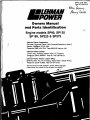
Owners Manual
and Parts
Engine models SP90, SP135
SP185, SP225 & SP275
Lehman Power Corporation
Pencader Corporate Center, 250 Corporate Boulevard, Suite E,
Newark, Delaware 19702, USA.
Telephone \30z) 454 7300. Telex 6853185 Lehmm UW.
Lehman Power Limited
1 Flson Way, Thetford. Norfolk, IP24 1HT, England.
Telephone (0842) 65566/7. Telex 617180 Lehman 0.
Lehman Power Taiwan Liaison Office
29-9 Wu Shan Tou, Pa LI Hslang, Taipei Hsien, Taiwan R.O.C.
Telephone (0)2 610 2885. Telex 34194 Yamei.
Thlo manual may bo mado avaliabio In eovorai diMoront longuogos.
PIQQOO contact your nooroot Lohmon company for availability.
V
A2
Door Lohman Ownor:
Wolcomo to tho growing family ol Lohman Power Marino diosol onglno uaora. You'll bo happy
to know that you havo chosen an onglno which Is heartily endorsed by loading boat bulldors
for Its quality, performance, fuel economy and long life. Your engine Is simple but highly
efficient. Its power, stamina and fuel economy will dollght you - especially II you've previously
operated gasoline power.
To obtain the best performance and tho longest life from any machine, it must be serviced
properly and regularly. Filters should be changed, coolant checked, oil changed at specified
times, otc. Follow the suggested schedule shown herein - It will add to your boating safety,
economy and enjoyment.
Perhaps the most Important slnglo rocommendetlon I can make to the now onglno owner is
"do not tinker"! If the unit Is running well - leave It alone! Adjustments and repairs should be
porformod only by a competent dlesol mechanic who has the proper knowledge and toofs.
Many times we ore requested to assist an owner who has attempted his own repairs. Unless
you know what you're doing, please "hands ofH
Lehman has a world-wide Service Network of Distributors and Dealers. Got to know your local
one through the Lehman Start Up Program and thoy will be on hand to help you, should you
need it.
Finally, always insist on genuine Lehman Parts. There are many examples of good boating
days ruined by the use of spurious engine and cooling circuit parts. Always specify Lohman
ports. If you have difficulty In obtaining them, please contact Lehman.
With propor caro your Lehman Powor onglne will provide many hours of carefree boating.
Thanks for the confidence you have shown In our Company by selecting our equipment. You
f
A2
mmuHMAN
mBPOWER
Genuine Parts
Lehman Replacement Parts
Lohman owners Increasingly roallso that using gonulno Lohman parts, supplied by a Lohman doalor can hoip onsuro
tho maximum ploasuro lor tho pleasure boat owner and tho maximum profit for tho commercial user.
Recognition
Lehman are Increasingly packaging parts In distinctive Lehman packaging and ensuring that many onglno
replacement parts, whore practical are painted red before sale. AH cooling equipment supplied by Lehman Is now
painted and packaged, a key area.
Any difficulty In obtaining genuine Lehman parts should be reported to your noorest Lehman location either USA or UK.
A Lehman publication 4C300 Is available to guide you through the extensive Lohman service notwork around tho
world - please ask for It.
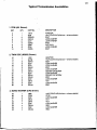
Cruise Kits
The most convenient method of obtaining many Lohman parts Is by purchasing our specially formulated Cruise Kits.
The wise boatman has always carried a selection ol replacement parts on his vessel, Lohman recognises this
excellent habit and has put 55 years of experience Into the right collection ol parts for most neods.
A. COASTAL WATER KITS
A series of kits formulatod for the commercial fisherman, the pilot boat operator and tho inshore cruising yachtsman.
ENGINE
SP90
SP135
SP185
' KIT*
207
209
211A
ENGINE
SP225
SP275
KIT #
' 2 1 1
211
The kits are packed in sturdy wooden boxes with carrying handles and contain:-
c
' '- -
Lehman selection of gaskets * A set of vee belts - OH filters • Lehman's selection of hoses - Zincs (Sacrificial
anodes) • Raw water pump service kit • Fuel filters • Lift pump repair kit • Thermostat • Selections of hardware
and washers • Plus another owners manual - let you keop this one at homo.
Note:- During 1987 Lehman are Introducing a new larger capacity oil filter 2N53 on the SP90 and SP135. This Is
not interchangeable with the old 2N50 please onsuro when buying a cruise kit that the correct filter for your
engine Is Included. Your dealer can make the change In the kit at tho time of purchase.
B. BLUEWATER EXTENSION KITS
To cut the cost of cruising and distant water work Lehman produces kits that "add to" tho coastal kits thus providing
a cost effective method of upgrading the basic kit.
>.
Tho Bluo Water extension kit Is mado for the long dlstancfe^son, the man who likes to go "foreign" and also the
hard working commercial operator.
"-vSs
ENGINE
SP90
SP135
SP185
KIT*
208
210
212A
ENGINE
SP225
SP275
KIT #
212
212
Tho kits are boxed, In wood, and contaln:Alr filter - Oil cooler • Solenoid - Oil and Fuol Filters • Hydraulic and luol hoses * Engine coolant pump • Complete
lift pump assembly - Base engine gaskets • Complete Injection lines • Manual and Distributor listing • Special
tools etc.
So, for securo cruising whether in Long island Sound or tho Malacca Strait, toko a Lehman Cruise Kit.
NOTE:- IF YOU OR A FRIEND HAVE A NON CURRENT LEHMAN ENGINE - CONTACT YOUR DEALER WE HAVE KITS FOR MOST LEHMAN ENGINES MADE.
A3
"MAKE IT EASY" ATTACHMENTS
Lohman has a wldo selection ol onglno attachments to moke your booting life easier.
Some examples are:Sump/oil pan pumps to take the mess out of changing oil, low cost, simple to operate and designed for your onglno.
Bilge pump/dock washing pumps that mount on the front of the engine, simple manual clutches to allow you to
wash down tho boot wherever you aro or clean the bilges In an approved area.
Romoto mounted filters to moke it easier to change them - particularly on the Turbo range.
Coll your Lehman dealer for the full range, in cose of difficulty consult Lehman Power Corporation In the USA
or Lehman Power Limited In the UK.
WE ARE HERE TO HELP YOU ENJOY YOUR LEHMAN ENGINE.
Your Owners Manual
This book contains operating and maintenance Instructions for the complete range of engines listed on the inside
front cover.
The life of your engine unit and the delivery of the high performance built Into it will depend on tho care It receives
throughout Its llfo. It Is the owners' responsibility to onsure that the engine Is correctly operated and that the
maintenance operations outlined In this book are carried out regularly after the specified hours of operation have
been reached. We consider It In your best interests to enlist the old of the authorised Lohman Power Distributor in
your area not only when repairs aro required, but also for regular maintenance with genuine Lehman pan's. This
regular maintenance will result in minimal operating and repair costs.
Where tho terms left and right appear in this book, they refer to the respective sides of the engine when v l o w o d
from tho roar (flywhool ond). Pistons and valves ore numbered from the front or timing cover end of the
engine, commencing with number 1 cylinder.
You may find that your engine assembly includes optional equipment not specifically covered in this manual. If you
hove any questions, contact your local Lehman Distributor.
Before Operation
Before oporating a now engine It should be thoroughly Inspected for damage likely to affect its subsequent operation
that may have occurred during shipment or during Installation In tho boat. Controls should bo Inspected to assure
they perform ond, of course, tho operator should be familiar with all controls, Instruments ond proper engine
operation, as well as, Insuring that all fluids are at their proper capacities.
Start Up Program
With this now range of engines, Lehman Powor is initiating on "onglne start" up program in many aroos. This
program consists of an Installation Inspection ond we ask that owners follow the recommendations of tho local
Lehman distributors to onsure tho maximum efficiency and pleasure Is obtained from your Lohman dlesel. Neither
Lehman Power nor its distributors ond dealers will bo responsible for any travel ond transporting costs associated
with this program. These costs would bo paid by tho owners. Please contact your local Lehman Powor distributors
for more details concerning this subsidized program in your area. If this program Is not yet available in your area,
we suggest the engine not be storied until the operator has read this manual thoroughly and familiarized himself
with the manner ol chocking tho engine oil level, coolant level, transmission oil level,etc. Tho chapters on
"molntononoo" and "running In" should be particularly noted.
NOTE: BEFORE STARTING TURBOCHARGED OR TURBO/INTERCOOLED ENGINES, REFER TO
"LUBRICATION" SECTION FOR INFORMATION REGARDING PRIMING OF THE TURBO UNIT WITH OIL.
A4
Running In:
DO NOT OPERATE YOUR NEW ENGINE AT HIGH SPEEDS IMMEDIATELY: EXCESSIVE WEAR OR DAMAGE
MAY RESULT.
NOTE:- BEFORE STARTING ENGINES FITTED WITH THERMOSTARTS REFER TO "ARTIC STARTING"
INSTRUCTIONS WITH ENGINE.
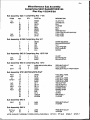
Long and dopondablo service may bo expected If proper coro Is token during the "break-In" period. Tho following
speed limitations ore recommondod;
Running T l m o
, RPM
15mln
Idle(nolood)'
15mln
800
30mln
1000
30mln
1200
4 hours
1500
Then follow tho dally ond other maintenance Instructions page A27.
•TURBO AND TURBO INTERCOOLED ENGINES WILL PRODUCE SOME WHITE SMOKE DURING THIS PHASE,
IT IS NORMAL, PARTICULARLY ON A NEW ENGINE, AND WILL DISAPPEAR WHEN THE ENGINE STARTS
TO WORK AND GETS WARM.
Do not operate your englno for excessive periods at low powor - your engine wonts to work - lot Itl
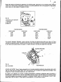
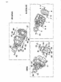
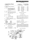
MODEL IDENTIFICATION AND SERIAL NUMBERS
The model and serial number of your englno Is easily located by reference to tho following drawing. T h o L o h m a n
P o w o r oorlol numbor, necessary for warranty authorization, and control, will be stamped on a raised pad on
the expansion tank, also on tho front right hand side of the timing gear housing. A dote code will bo stamped on
a pad located bohlnd the Injection pump. Tho cubic inch displacement of the unit Is stamped on a similar pod at
the rear, starboard side of tho cylinder block.
SERIAL No. PAD
PLATE INDICATES ORIGINAL CRANKSHAFT JOURNAL SIZES
A5
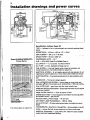
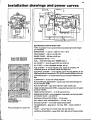
Installation drawings and power curves
8poolflootlon L o h m a n 8upor 90
TYPE - 4 cylinders in lino, 4 cyclo ovorhoad volvo naturally aspirated diosol
onglno.
BORE/STROKE - 4.22 Ins x 4.524 Ins: 107 x 115mm.'
DISPLACEMENT - 254 cu Ins: 4.150 liters.
GROSS POWER - 90 bhp at 2600 rpm. .
8upor 90 8 A B J270/DIN 6270
P o w o r Curvo
L
,
' '
''
COMPRESSION RATIO - 16.1:1
FUEL - ASTM D975 Class 2D or BS2869 Class A1.
OIL CAPACITY - 11.2 US quarts. 10.6 liters {Initial fill)
OIL FILTER - full flow, disposable cartridge, spin on.
FUEL SYSTEM - In line fuel injection pump, engine oil lubricated, with
mechanical governor, ond flexible braided fuol supply lino.
ELECTRICAL SYSTEM - 12 volt negative ground with stop solenoid, 24 volt
negative ground and Insulated return 12 or 24 volt aro also available at extra cost.
STARTING MOTOR - 1 2 voH electrical solenoid, 24 volt, also available at extra
cost.
ALTERNATOR - 70 amp with voltage regulator.
RAW WATER£OOLING SYSTEM - tubular coppor or cupro-nlckol hoot
exchanger ^Oi'zlnc ontkorroslon pencil: optional 60% or 100% keel cooling.
RAW WATER PUMP - goer drlvon high How rubber Impeller typo.
FRESH WATER COOLING SYSTEM - pressurized fresh water circuit for onglno
and exhaust manifold.
FRESH WATER CAPACITY - 15.84 US quarts: 15 liters.
ENGINE MOUNTINGS - In llnoor stoppod or transmission mounted, adjustable
antl-vlbratlon mounts - soo price list.
MAXIMUM INSTALLATION ANGLE - 15' roar down.
DRY WEIGHT LESS TRANSMISSION - 1080 lbs; 490kg.
EXHAUST OUTLET - 30 water cooiod exhausl olbow, or straight dry exhaust
(tango.
Fuol consumption (or typical Hull
TRANSMISSIONS - Borg Warner, Newage PRM, - olhors available on request.
FINISH - Lohman Rod with chrome rocker box, air flltor and filler caps
APPROVAL STANDARDS - Lloyds, RINA, DNV. ABS with others available.
(Japan small cralt Inspectorate ponding).
A6
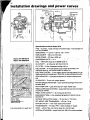
Installation drawings and power curves
Spoolflootlon L o h m o n 8upor 139
'TYPE - 6 cyllndors In lino, 4 cycle overhead valve naturally aspirated dlosol
onglno.
BORE/STROKE - 4.22 Ins x 4.524 Ins: 107 x 115mm.
DISPLACEMENT - 380 cu Ins; 6.22 liters.
» GROSS POWER - 135 bhp at 2600 rpm.
8upor 139 DIN 6270/
8 A B J 2 7 0 P o w o r ourvo
COMPRESSION RATIO - 16.1:1
,
r
\
" /'"
FUEL'-ASTMD975 Class 2D or BS2869 Class AU
g
' ' ~"
OIL CAPACITY - 19.76 US quarts, 18.7 liters (Initial fill)
:OlL FILTER - full flow/disposable cartridge, spin on.
FUEL SYSTEM - Inline fuel Injection pump, engine oil lubricated, with
mechanical governor, and (loxiblo braided fuel supply line.
• ELECTRICAL SYSTEM - 12 volt nogat'lvo ground with stop SOlonold, 24 volt
negative grond and insulated return 12 or 24 volt, aro also available at extra cost.
STARTING MOTOR - 12 volt oloctrlcal solenoid, 24 volt also available at oxtra
cost.
'
1
ATLERNATOR - 70 amp with voltago regulator. •
' RAW WATER COOING SYSTEM - tubular copper or cupro-nlckol heat exchanger with zlnc^j-corrosion pencil; optional 60% or 100% kool cooling.
RAW WATER PUMP - gear driven high flow rubber Impeller typo.
FRESH WATER COOLING SYSTEM-pressurized fresh watorclrcultforonglne
• and exhaust manifold.
1
FRESH WATER CAPACITY - 19 US quarts; 18 liters.
ENGINE MOUNTINGS - In line or stepped or transmission mounted, adjustable
antl-vlbratlon mounts - see price list. '
MAXIMUM INSTALLATION ANGLE - 15* roar down.
DRY WEIGHT LESS TRANSMISSION - 1374 lbs; 623 kg.
EXHAUST OUTLET - 30* wator coolod exhaust olbow, or straight dry exhaust
flange.
.v
Fuol consumption for typical. Hull
TRANSMISSIONS-- Borg Warnor. Hurth, Nowago PRM, Twin Disc - others
available on roquost.
i FINISH - Lehman Red with chrome rocker box, air filter and filler caps'
APPROVAL STANDAROS - Lloyds. RINA, ONV, ABS and others available.
(Japan small craft Inspectorate pending).
A7
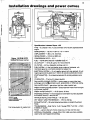
Installation drawings and power curves
r
li
>. t.
I
L
h-
***
, X >
«
Jj
--/.VI:.--
1
• it nv
•fKM—
i4Ul
1
••
r
— ™'J
j
Spoolflootlon L o h m a n 8upor 189
TYPE - 6 cylinders In lino, 4 cycle overhead valve dlosel onglne. Turbo
charged.
BORE/STROKE - 4.125 Ins x 4.524 Ins: 105 x 115mm.
DISPLACEMENT - 363 cu Ins: 5.95 liters.
GROSS POWER - Super 185 - 185 bhp at 2500 rpm.
Supor 189 8 A B J 2 7 0
S u p o r 1 8 9 DIN 0270
COMPRESSION RATIO -14.7:1FUEL - ASTM D975 Class 2D or BS2869 Class A1.
^ '
OIL CAPACITY - 23.5 US quarts. 22.0 liters (Initial fill)
OIL FILTER - full flow, disposable cartridge, spin on.
FUEL SYSTEM - In line fuol Injection pump, onglne oil lubricated, with
mechanical governor, ond flexible braided fuel supply lino.
ELECTRICAL SYSTEM - 12 volt negative ground with stop solenoid, 24
volt negative ground and insulated return 12 or 24 volt, aro also available
et oxtre cost.
STARTING MOTOR - 12 volt electrical solenoid, 24 volt also available at
oxtro cost.
i
ATLERNATOR, - 70 amp with voltage regulator.
RAW WATE$-COOLING SYSTEM - A cupro-nlckei heat exchanger with
zinc anll-corroslon pencil.
RAW WATER PUMP - gear driven high flow rubber Impeller type.
FRESH WATER COOLING SYSTEM - pressurized Iresh water circuit for
onglno & exhaust manifold.
FRESH WATER CAPACITY - 24.3 US quarts: 23.0 liters.
ENGINE MOUNTINGS - In lino, adjustable high grade antl-vlbratlon mounts
- soo price list.
MAXIMUM INSTALLATION ANGLE - 15' rear down, 4° front down.
DRY WEIGHT LESS TRANSMISSION 1524 lbs; 891 kg.
EXHAUST OUTLET - 4 Inch wator cooled oxhaust elbow.
Fuol consumption for typical Hull
TRANSMISSIONS - Twin Disc, PRM - others available on request.
FINISH - Lohmon Rod with chromo rockor box, ond filler caps
APPROVAL STANDARDS - Lloyds, RINA, DNV, ABS, JCI and othors ore
available.
A8
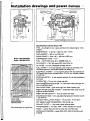
Installation drawings and power curves
m m . M i n i , iwmi
i.m
-mi-••im-
ilk-
Spoolflootlon L o h m a n S u p o r 228
TYPE - 8 cytlndors In lino, 4 cyclo ovorhood volvo diosol onglno turbo chorgod
ond Inlorcoolod.
BORE/STROKE - 4,125 Ins x 4.524 Ins: 105 x 115mm.
DISPLACEMENT - 363 cu Ins: 5.95 liters.
GROSS POWER - 225 bhp ot 2450 rpm.
Supor 229 DIN 6270
8upor 229 8 A B J 2 7 0
COMPRESSION RATIO - 14.7:1
<
FUEL - ASTM D975 ClGSS 2D or BS2669 Doss A1.
OIL CAPACITY - 23-5 US quarts: 22.0 liters (Initial fill)
OIL FILTER - full How, disposable cartridge, spin on.
FUEL SYSTEM - In line fuol Injection pump, engine oil lubricated, with
mechanical governor, ond floxlblo braided fuol supply line.
ELECTRICAL SYSTEM - 12 volt negative ground with stop solenoid, 24 volt
negative ground ond Insuiatod return 12 or 24 volt, aro also available at extra cost.
STARTING MOTOR - 1 2 volt electrical solonoid, 24 volt also available at extra
cost.
ALTERNATOR - 70 amp with voltage regulator.
RAW WATER COOLING SYSTEM - tubular cupro-nlckel heat exchanger with
zinc antl-corroslon perreJIi
RAW WATER PUMP - gear drlvon high flow rubbor Impeller type.
FRESH WATER COOLING SYSTEM,- pressurized fresh water circuit for onglne
& exhaust manifold.
•
FRESH WATER CAPACITY - 21.6 US quarts: 23 liters.
ENGINE MOUNTINGS - In lino or stopped or transmission mounted, adjustable
anti-vibration mounts - eoo price list.
MAXIMUM INSTALLATION ANGLE - 15° roar down.
ESESEBSF
'
Fuol consumption lor typical Hull
DRY WEIGHT LESS TRANSMISSION - 1574 lbs: 714 kg.
EXHAUST OUTLET - 5 Inch wator cooled oxhaust elbow.
TRANSMISSIONS - Borg Warner, Twin Disc, PRM - others available on
request.
FINISH - Lohmon Red with chromo rockor box and filler cops
APPROVAL STANDARDS - Uoyds, RINA, DNV, ABS, JCI with others available.
A9
Installation drawings and power curves
)t\.
-
J
Spoolflootlon L o h m a n Supor 279
TYPE - 6 cylinder, 4 cycle overhead valve dlosol onglne. Turbo charged and
twin flow Intorcooled.
BORE/STROKE - 4.125 Ins x 4.524 Ins; 105 x 115mm.
DISPLACEMENT - 383 cu Ins; 5.95 liters.
GROSS POWER - 275 bhp at 2500 rpm.
Supor 275 DIN 6270
Supor 279 8 A B J 2 7 0
COMPRESSION RATIO - 14.7:1
<
FUEL - ASTM D975 Class 2D or BS2689 Class A1.
OIL CAPACITY - 24 US quarts: 22.5 liters (Initial fill)
OIL FILTER - full How, disposable cartridge, spin on.
FUEL SYSTEM - Inline fuol Injocllon pump, onglno oil lubricated, with
mechanical governor, and flexible braided fuol supply lino.
ELECTRICAL SYSTEM - 12 volt nogallvo ground with stop solenoid, 24 voll
negative ground and Insulated return 12 or 24 volt, are also available at extra cost.
STARTING MOTOR - 1 2 volt oloctrlcal soionold, 24 volt also available al oxtra
cost.
,
ATLERNATOR - 70 amp with voltage regulator.
RAWWATERCOOLING SYSTEM-'cupro-nlckel heat exchanger with zinc anilcorrosion pencil.
RAW WATER PUMP - gear driven'high flow rubber Impollor typo.
FRESH WATER COOLING SYSTEM - prossurlzod froah wotor circuit for onglno
and exhaust manifold.
FRESH WATER CAPACITY - 24.3 US quarts; 23.0 liters.
ENGINE MOUNTINGS - In lino, adjustable high grade antl-vlbratlon mounts 800 prlco list.
B
MAXIMUM INSTALLATION ANGLE - 15° roar down. 4 front down.
DRY WEIGHT LESS TRANSMISSION - 1574 lbs; 714 kg.
EXHAUST OUTLET - 5 Inch walor cooled exhaust elbow.
TRANSMISSIONS - Twin Disc, PRM - others available on roquest.
Fuol consumption for typical Hull
FINISH - Lehman Rod, with chrome rocker box, ond flllor cops
APPROVAL STANDARDS - Lloyds, RINA, DNV, ABS, JCl ond others available.
^
A10
Specifications
254cu/ln.4Cyl.
TYPE
380cu/ln.8Cyi.
383cu/ln8Cyi.Turbo.
ond6Cyl.Turbo/lnt.
4 CYCLE, OVERHEAD VALVE, DIRECT INJECTION
2722E
2725E'
2726E
2728E
SP90
SP135
SP185.
SP225/SP275
_300lb8 per sq. In Ini at 215 rpm ± 80 PSl botwoon Cyl
1-2-4-3
1-5-3-8-2-4
1-5-3-8-2-4
r.r. w facing llywhool
i
MODEL
MODEL (LEHMAN)
COMPRESSION PRESSURE MIN
FIRING ORDER
CRANKSHAFT ROTATATION
GOVERNED SPEED (Max) NO LOAD
UNDERLOAD
IDLING SPEED
EXHAUSTSIZE •
EXHAUSTBACK PRESSURE (Max)
COLDSTART
VALVES
VALVE CLEARANCE (hot/cold)
PISTONS
COMBUSTION CHAMBER
PISTON RINGS
2650
2600
2650
,2600
_ 8 2 5 to 875
4" ID HOSEi.
.3.5" - ID HOSE:
.1V6 lb/sq.ln. (3.0" Morcury).
_AutO Excoss fuol dovlco_
Froo turn'typo
.Iniot & Exhaust 0.015*
.Aluminium alloy, tin platod.
_Machinod In piston crown.
.2 Compression; 10il control:
2600
2500
.5" ID HOSE
.In & Exh. -
.018"
.3 compression+ 1 oil control
CAMSHAFT
CRANKSHAFT
MAIN BEARINGS
LUBE SYSTEM:
MINOILPRESSURE
OILTEMPERATURE (range)
LUBRICANT
Abovo 901 ambient
.Cast Iron alloy; Gear drivbn.
Stool forging
7
.41 PSl at 1800 RPM & .47 at 2000 RPM.
185 - 230*F.
'
SAE 3QL.SAE 20W/20.
_ S A E 10W_
Shell and tube typo heat exchanger
22' BTDC No. 1 piston ' 22 BTDC No. 1 piston
24* BTDC No. 1 piston*
_
4' holo type
.
.SP275 - Tost Prossuro 265/275 Bar. - others 206/218 bar.
.Diaphragm with hand priming lever
Piston,typo
82' - 94*C
''
20 to 90°famblont
Below 30°famblont
OIL COOLER
TIMING
INJECTORS
PRESSURE
FUEL LIFT PUMP
OPERATING TEMP.
MAXIMUM TEMP.
CIRCULATION
SUGGESTED BATTERY
LOCKTORQUE
RUNNING TORQUE
HEATEXCHANGER
RAW WATER PUMP
MANIFOLD. EXHAUST
MANIFOLD, INTAKE
AIR FILTER ELEMENT
ENGINE MOUNTINGS
FUEL LINE
TACHOMETER ADAPTOR
FAN BELTTENSION
s
:
.159 lltors/mln;
.180 lltors/mln
.120 AMP/HR.
.37.5 ft/lbs., 1240 amp. draw Max.
I5ft/lbs 690 amp Draw Max
Shotl and tube typo, 2 pass__
.Bronzo, single Impeller type, goar driven.
Gray Iron, frosh water, coolod
Intftprnl with OxhauSt.
.Wire Mosh
.Polyurethono. 40 pore, replaceable:
.Rubber compound,, adjustable.
.3/8" Recommended. Reduce to 5/16" at onglne.
:
Turns C.C.W. at 1/2 englno spoed. Adapts to 7/8" - 18 forrule
1/2" froo mnunmnnt
'May be adjusted In certain conditions to 20° BTDC No. 1 Piston
A11
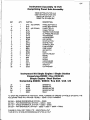
LEHMAN POWER WARRANTY (LIMITED)
Lehman Power Corporation ond Lohmon Powor Limited (horlnottor collod "tho Company") grant the following Limited
Warranty to tho first rotoll purchaser of Lehman Marino Engines In respect of which this Warranty Is issued.
1 Tho Company warrants each new assembly or component part of our manufacture to bo Iroe from defects In
matorlal and workmanship for a period of ono year from tho date of purchase by the first retail purchaser or first
charter date If not retailed, the period during which tho ono year may bo claimed will oxtond to a maximum of
30months from tho ex-Lehmon factory doto. providing tho onglno has boen proporly stored. This Warranty Is
only Initiated upon receipt by tho Company of the completed Warranty Card, supplied with each new unit. Warranty
sorvico is obtainable from any authorised Lohmon Powor Distributor or Dealer. The Company reserves the right
to ropoir or replace at our solo option any defective item.
. ,
2 In the event of eny defect appearing In any part or ports In the list below within 12 months Irom tho timo when
they ore dollverod now to tho first retail purchaser thereof ond tho pan or ports alleged to bo defective ore
returned promptly to any authorised Lehman Distributor or Dealer the Company undertakes to hovo It or them
oxamlnod, ond should any defect duo to faulty materials or workmanship bo found on such examination to have
It or them repaired or to have a replacement port or ports supplied Free of Charge. An allowance will be made
for tho labour normally involved in tho removal of defective parts and tho repair or replacement of these Items,
but this allowance will not Include any additional work then required by reason of tho typo of equipment, tho
place or manner in which the engines ore housed or Installed. Tho allowance will be based on the direct labour
tlmos allowed by tho Company to authorised Lohmon Distributors or Ooalors.
3 Ports repolrod or replaced under terms of this Warranty ore covorod for tho remaining port of the Warranty period,
provided that they are Genuine Lehman supplied ports.
4 This Warranty will not apply:
(a) If the defect Is In any way due to tho use of parts not mado or approved by the Company.
(b) If tho defect is In any way due to misuse, wrong application or nogloct Including poor servicing or bod storage
when out of sorvico.
(c) Tho articles oro covered by a soparoto Warranty.
(d) If any Identification numbers oro altered or removed.
(o) If tho goods oro altered, modified or used In such o manner os to subjoct them to abnormal woar or strain.
• (f) To engines which hove been repolrod or oitored In o manner which In tho Company's sole Judgement may
affect this performance or reliability.
(g) Failure resulting from Improper Installation of tho onglne and transmission.
5 Ports submitted for Inspection will be scrapped upon completion of the claim unless prior arrangements were
mado to havo them returned to tho customer by the Lohman Distributor or Dealer.
8 Persons dealing with tho Company's products ore not the ogonts of tho Company and have no authority to
assume any obligations on Its behalf.
7 For tho purpose ol this Warranty 'owner' Includes a person renting or loosing tho goods for his own use under
a lease purchase agreement.
8
Tho parts to which this Warranty applies oro:
/
" (a) Fresh water expansion tank
(b) inlet ond exhaust manifold
(c) Air filter
(d) Soo water pump
(o) Sea wator/frosh water heat exchanger
(f) Sea weter/transmlsslon oil coolor If supplied by the Company.
(g) Soa wator/ongino oil coolor
(h) Bell housing if supplied by Company.
G) Soa water pipes botwoen tho soa water pump output and the soa woter outlet point
(k) Frosh woter plpos for tho engine cooling circuit, excluding any pipework feeding heating appliances flttod
to tho vessel and any defect arising tho re from which may affect the normal performance of tho onglne ond its
marlnization
A12
(I) Englno oil food plpos ond oil filter block
(m) Transmission oil food plpos If supplied by tho Company
(n) Engine stop solenoid If supplied by tho Company
, '
(e) Engine mounting brackets
(p) Englno flexible mountings If supplied by tho Company
(q) Othor ports such as instruments controls, etc., which may novo been supplied by the Company at tho
request of tho bootbulidors, but which do not habitually form port of tho Company's contract with tho
boatbulldor and which thorofore cannot bo Itomlsed herein
t
(r) Othor parts which may bo supplied by the Company from tlmo to time. (s) Tho Ford base engine
1
9 The transmission is covered by Its manufacturers Warranty
, :
\
10 The Starter motor and Injection equipment is covered by CAV/Lucas Warranty
!
'
1
11 The Peugeot base engine is covered by tho Warranty from Peugeot Motors Soclots Do Motour C.L.M. through
LPC/IPL
'
12 The following services, expenses and conditions oro not covered by Lehman Powor Warranty
(o) Damaged or less related to shipping and handling
'
(b) Towing charges, dockage, storage loos, telophono colls, fuol, loss of revenue, transportation charges (othor
than miloogo ond tho mechanic's travel time) overtime pay, loso of or damage to any personal property
and cost of lubricants and transmission fluids except when replacement or replenishment of fluids Is required
following a warranty repair
(c) Preparation costs related to warranty such as, moving furniture, bulk hoods, deck plates, carpet, or any
other equipment causing engine inoccessoblllty.
(d) Failure caused by use of improper lubricant, overheating or failure to follow recommended maintenance
schedules as spelled out In the Lohmon Power Manuals.
(e) Cost of repairs due to misuse, accidents, negloct racing and Installation defects, as well as, shaft misalignment
(f) Any consequential losses arising from failure of components under warranty
13 All claims under tho Warranty should be addressed to the nearest Lehman Distributor or Doolor. In tho event
(hot there Is not o local authorised Distributor or Dealer, claims may be sent to:
14 All warranty claims must bo submitted within 30 days of the work boing completed, or warranty may bo Invalidated.
Lehman Power Corporation
Pencader Corporate Center, 250 Corporate Boulevard,
Suite E, Newark, Delaware 19702, USA.
Telephone (302) 454 7300. Telex 6853185 Lehmm Q.
Lehman Power Limited
1 Fison Way, Thetford, Norfolk, IP24 1HT, England.
Telephone (0842) 65566/7. Telex 817180 Lehman G.
Lehman Power Taiwan Liaison Office
»
29-9 Wu Shan Tou, Pa LI Hslang, Taipei Hsien, Taiwan R.O.C.
Telephone (0)2 610 2885. Telex 34194 Yamel.
A13
LEHMAN WARRANTY - Continued
Every complete Lehman Marine Engine is provided with this "Owners manual" which
explains all warranty terms In detail. Pages A11 and A12.
SPECIAL NOTE:
.
Warranty does not cover any loss of operating time while engine may be out of service,
or damage to boat In which: the engine may be Installed.
A reasonable amount of time (as set forth in the Flat Rate Manual) Is authorised to
accomplish warranty service, it is assumed that engine and associated equipment Is
readily accessible for such, service or removal, if required. We cannot be responsible
for servicing or removing inaccessible units.
;
Finally It is most Important that your Lehman Warranty be mailed prior to start-up.
Claims for warranty will not be honoured unless the attached form has been preregistered.
., '
Fill out the Card, and retain the details below for your own record.
Serial No.
Engine model
Transmission Model
Owners
Serial No.
Date _
_ Ratio
Name/Address
Phone (
)
Boat Name
Hull No.
Boat Home Port/Address
Boat Mfgr.
Engine Purchased From
Address
Model
Length
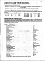
HOW TO USE THIS MANUAL "
r'
This manual is divided Into soctlons as follows:
SECTION A - Pages Nos. Al/on - Gonerol date, specifications, Installations, adjustments, maintenance, etc.
Soo Index below.
SECTION B - Pago Nos. Bi/pn - Ports Identification of Ford base englnos. Soo Index on pogo B-i.
:
SECTION C - Page Nos. Cl/on - Ports Identification of Lohmon Marino ports. Soe Iridox page"C 1.
In ordor to provide o slmplo.method of Identification, all mobols Included heroin hovo been osslgnod o "code", letter
08 follows:-
i
ENGINE CODE
M-Supor 90
N-SupeM35
1
4
V-
CU/IN ' NO. CYLs!
254
* ' 4
380*
B^
;
r
*
YEARS
6/B28/82-
, ENGINECODE
* S-SuporSPl85
, P-SuperSP225
\ T-Supor SP275
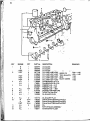
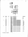
Instructions for Ordering Paris
NO. C Y L S : ^ YEARS .,
CU/IN
383
383
383
,
8
8
8
'
,
.6/62' 8 / 8 2 6/62-
•,/
Parts listed In this monuoi moy bo ordored through any Lohmon distributor or dealer or, In areas not served by o
dl8trlbutor/dooior, direct from tho Lohmon companies. Prlcos will bo quoted upon request. In ordor to provont orrors,
ploose ordor any roqulred Horns by exact part number and namo of port. Whon ordering ports, please advlso modol
number and serial, nurriber.iof the onglno.
'
Index - Section, A
V
Air bleeding tho fuotsystemi
. i
•. -A18 •
Boforo operation
A3v . 'I.
Bleeding the fuel 'System
A18
Break-In
. . . .
.* . "
A4
Controls
...;<•.'
A18
Cooling system
A19.A20.A21
Dimensions, onglno
r?.' ^.n.
^ - I f ) , ^W-'l• • A5,A8,A7,A8,A9
Dralnlngonglne
<
. A21.A2B
Electrics '
. I . J .
. '.•
<• . V / V u \ ..... •! . . r.v, A22;A23
< /
Fault-finding guide .*
•.
• • A15
i • •
Filters, fusl & Sir•. . . n \ . , . .
. . ,
. . . .
. A19.A27 ,
Fuel system . .
.
v..-.".
V
A17,A18 A19
Identification of models- . .
. . >: . . . •
- j ' . - ^ ^ • • • • A4.A14
Idling adjustment
.
^ • . • .>
.~ ••->
A29
- •Lift pump .
.•••.)
• • • A1B.A19
Lubrication system \ r. •
. . . . .
. A23.A24.A25
Maintenance .! •. i . *.
<..i
• ,"• • • A27.A28.A29 / •
Minor repairs
A27,A2B
Nameploto data" .
. . ..v . . . / . . - u * ;•
vv*v -' • • •
i • . , - ,\
Oil rocommondotlons
. . . - k* .>
* . - i / g . • • A24.A25 .
-,
.> ,
Powor charts
, . . . . . . , . • . A5,A8,A7,A8,A9
Runnlng-ln
. . . . . . . . . A4
Specifications
. •.
.. ' . / , . ' , . ' .
. . A5,A8,A7,A8,A9,A10
Starting, stopping engine;
. . ...
-v,* -y
• ; • • A3.A18.A17.,
,
Tachometer take-off
. A22
Timing the;Injection.pump
. . ..<.J
j • • •
Transmission
.
......
r ,-•)'•, • • •
\ .* ' •
- ?. '
Trouble-shooting chart,,,. .
A15
Volvo a d j u s t m e n t s .
. -.
* ..
A10.A27
« ^
Voobelt 7 .
. . . . .
,.
,.
• .. A28 .
Warranty . . . . ,
. . . A11.A12.A13
,
Water heater, connection
. M
^. . •
• • A30
Winterizing
A21.A29
Wiring dlogrom .
.
. . - ,
A23
(copyright 19B3- LEHMAN POWER CORPORATION Newark, Delaware)
B
1
v
i
V
V
i
l
|
r
(
1
i
(
;
A 4
;
(
t
(
;
n (
{
!
A
1
A 2 5
;
v
i V
9
A 2
t)
t
A15
LEHMAN DIESEL OWNER'S FAULT-FINDING GUIDE
t Particular attention should bo dlroctod to tho most common trou6/o-spofs mark by on asterisk*
ENGINE WILL NOT START
i
Startor does not
. cronk onglno
'Battery run down
Bottory coblo or switch
wlro disconnected.
'Faulty starter switch.,
Faulty storting motor
Starter drlvo doos not
engage flywhool.
i
it
1 .
Startorcranks
onglno slowly
M
'Battery partly run down
'Battery terminals looso,
dirty or corroded.
Faulty startor solonold.
Foully startor
Englno oil too heavy.
Startor cranks
onglne
•Injection timing Incorroct
Poor cyllndor comprosslon
Blocked olr cloonor ' - •
Mechanical -
Fuol System.
L
1
1
' Fuol doos NOT roach
• Injoctlon pump ' '
Fuol Roachos injoctlon
Pump
"Air loak InTuol line
Fuol tank empty '
'Stoppage In fuel line
Stoppage in fuel filter
Water In fuel' system
Faulty lift pump
"Air In fuol system
'Stop control ongagod
Controls binding
Faulty Injectors
ENGINE STARTS
ENGINE RUNS INTERMITTENTLY
ENGINE KNOCKS
Idle Adjustment too low
*Alr - Looking fuol system
Fuol (lift) pump diaphragm* worn
Fuol flltor (s) clogged • *
Sticking velvos
Fuel Tonk near ompty
*Alr In fuol systom
Oil level (pressure) low, worn
bearings
Incorrect gredo fuel oil
incorrect Injoctlon liming
Faulty Injoctor
Sticking valvo or rocker arm
Piston slop
v
1
, v
ROUGH IDLING
'
'
'Air In fuol system
*ldlo adjustment set too low
Dirty or faulty Injoctors ,
Injector plpos loose, crocked .
or broken
. .
Incorroct Injection timing. '
Restricted fuol flltor
' ' '
Faulty lift pump
Sticking valves
Broken velvo springs
i(
ENGINE MISFIRES j
'Injoctor ptpo looso, broken or
crocked
Inloctors dirty
*Alr looking In fuol system
Sticking valve or rocker arm
Sticking piston rings
Englno noeds top overhaul
ENGINE NOT DELIVERING
FULL POWER '
"Air fuol system
Engine ovorheatod
Injection timing Incorrect
incorroct valvo clearances
Dirty air clooner(s)
Faulty injectors
Feulty Injoctlon pump
Stop control partly ongagod
Sticking valves
Worn piston rings, or bores
Faulty lift pump
Restricted fuel filters
ENGINE OVERHEATS
'Insufficient water supply
Fresh wator not circulating
a) Looao or broken veo bolt
b) Hoses clogged or collapsing while
running at high speed
c) Faulty thermostat
d) 'Clogged heat exchanger •
o) Clogged blood hole In thermostat
Raw water flow insufficient
a) 'Clogged sea wator'stralnor
• •
b) Wator Intake scoop damaged or lost
c) Sea cock closed
d) Water pump Impotler damaged
e) 'Heat exchanger or oil coolers
cloggod.
Low croncaso oil level
Incorroct Injection timing
Engine noeds top overhaul
ENGINE EXHAUST SMOKES
Fuol, poor grade (black smoke)
Crankcoso overfilled (blue smoko)i
Cold englno temperature (white or
lite blue).
'Propeller too largo (black smoko) Max. speed stop screw sot too high
for load (black smoke).
• "
Propollbr too small (whlto smoke),
Incorrect injection timing
Faulty boost control unit
,JI
A16
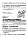
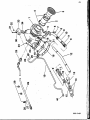
Controls, Starting & Stopping Engine
No amount o< onglnoortng Ingenuity orcaro In manufacture con substitute (or tho nood of knowledge on tho oporation
ond ovoldance of mis-use by the' operator. Ji-Is-Important to be familiar with all controls so as to know how to
properly operate your onglne.
• _ , , . < ,
Refer Fig. 1. To stop engine, the stop lover should bo moved as far as it will travel towards tho front of the onglno
and hold until engine is fully stopped. This lever cuts off tho supply of fuel to tho Injection pump. (NOTE before
shutting down engine It should always bo allowed to Idle for about two minutes, particularly after extended periods
of cruising - This Is particularly Important with Turbo and Turbo Interc'oolod engines).
Englno speed control Is the longer lover at side of injoctlon pump (Fig. 2.) Moving toward front of onglno increases
englno speod.
~M
1
An excess fuol device permits additional fuol to bo supplied by the injoctlon pump to assist In starting the engine
from cold. This device is (ully automatic In oporation. <
NOTE: All engines aro equipped with an
eloctrlc shut down solenoid. To stop press
stop button until engine stops running, then
release button.
Injootlon P u m p Control©
1. Stop Lovor
2. Spood Control Lovor
1
Starting all Naturally Aspirated Engines
To start onglne when cold - mako certain that transmission Is In neutral position and that all boat accessory
equipment (bilge pump, extra alternator or generator, hydraulic pump, winch, etc.) Is disengaged. Check that engine
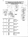
stop lovor Is fully towards rear (flywheel end) of onglno. Sot throttle lovor to % open position. Pross starting button
to operate startor. As soon as engine starts, roleose starling button to operate speed control lovor to worm-up
(Idling) spood of 700-,800 RPM. If englno falls to start within 5-soconds, release storting button.Try again aftor
ollowlng^ sufficient time for all moving parts to stop; Onco englno has started, It should bo allowed to roach 170°F
before full load is applied.
To restart engine when warm, samo procedure as'abovo except set speed control lover to approximately mid-point
of Its travel.
\
s.
' '
~ ^ •,
' '
"
Starting all Turbocharged Engines
Serious damage to tho turbochorger bearing can result from Inadequate lubrication if tho following recommendations
are not observed.
'
> \ t •>
Prior to tho first start aftor a turbochorger has boon newly Installed or if for any" reason the oil supply to the
turbochorger has boon disconnected, you should Insure that tho turbochorger housing is flllod with onglno oil before
reconnecting tho oil feed pipe. In these circumstances, or In cases whero tho onglne is being started for thollrst
time aftor an oil change or aftor a period of 4 weeks or more without use, tho following procedure must bo used;
1) Engage elthor manual or electric stop control
2) Crank the onglno with tho startor'rhotor for 15 seconds
3) Dlsongago stop control
•
'
'
>
4) Start englno in normal fashion and allow to Idle for 30 seconds minimum boforo applying load
This onsures an adequate oil supply to tho turbochorger bearing. Tho onglne should bo allowed to Idle, without
load, for 2 minutes prior to shut down to enable tho oil to dlsslpato tho hoot from tho turbochorger bearing.
A17
Stopping all Engines,
'5
Tho onglno should bo Qilowod to slow Idle lor approximately 2 mlnutoe boloro stopping, ospoclolly aftor extended
.periods of full load and full spood operation. This Is particularly Important In tho caso of-turbochorgod engines.
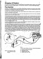
Fuel System
CAUTION: -Your Injection,pump is o very accurately machined piece of oqulpment.ond requires corofui handling
ond adjustment. No'repairs'other than shown herein, should be entrusted to other than a diosel repair facility having
tho required tools, knowledge and test/calibration equipment.,
CAUTION: Never bend the Injection pipes (which connect injection pump to Injectors) as this may unbalance the
volume of fuol delivered to each cylinder.
.
;
CAUTION: Do not use o galvanized fuel tank as the zinc coating roaots with the fuel oil ond forms .undesirable
compounds which can foul tho Injection system.
'^
•
•
^
(
Tho fuel Injecton equipment is mode to very accurate limits end therefore, ovon the smallest particle of dirt entering
the system will d03troy Its efficiency by causing blockage or scoring or premature wear on highly finished parts, A"
clean fuel system Is absolutely essential. Insure scrupulous cleanliness when handling fuel or fuel system compo
nents. At ail times mako'certaln that woter Is not allowed to contaminate the fuel oil. Try to make a practice olrofuoflng
out of the rain: Use a fine gauze flltor funnel and always wipe the fuel tank around the filter cap before andafter
filling andrimme^lately[replace'the cap.
* ^
'
''!
'
'
'
An efficient, large size primary fuel flltor and water separator (coolescor) Is doomed a necessity in order to prevent
foreign portlclds'.'rdachlng the Injection equipment on your engine.
Your engine'Is, equipped with secondary fuol filters which filter out contaminates that may find their way through»
tho primary.filter. These filters (see Fig. 3/4/5) located towards roar of engine block, right side, have elements which \
should be replaced once oach'soason or at least each 200 hours (which ever comes first) under normal conditions.
(When'replacing (liters, use new gaskets or sealing rings to prevent olr leeks.) Following filter replacement, bleed
air from fuel system as later described undor "bleeding the fuel system". Excess fuel delivered to. the Injectors by
the Injection pump Is collected by a tube located under the rocker arm cover (see A, Fig. 2) and delivered to fitting
C, Fig. 4 located at roar, right side of cylinder head. This fitting should bo connected to top of fuel tank by V* (min.)
fuol line, it is recommended that tho Boot Builders installs
lolls a short section of flexible tubing in this line to prevent
breakage due to engine vibration:
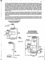
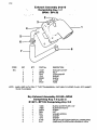
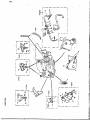
TYPICAL FUEL'SYSTEM, NATURALLY ASPIRATED ENGINES
NOTE: All N/A Engines are fitted
with a common fuol return
lino C D .
- i
A
B
C
D
-
Primary fuel filter wator separator
Secondary fuel filter
Excess fuel return tube
Injection pump return tube
A18
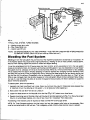
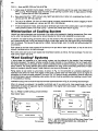
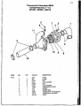
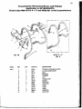
TYPICAL FUEL SYSTEM, TURBO ENGINES
A - Injection pump roturn tubo,
8 - Flltor Proas Relief Lino
C - injoctor Look Oft Lino
'NOTE: "ON ENGINES MADE IN LATE 1985 ONWARDS - FUEL RETURN LINES MAY BE INTERCONNECTED
TO SIMPLIFY PIPING" (Roturn lino to tank must bo 10mm bore mln.)
Bleeding the Fuel System
Bleeding air. from the fuel system may wol) bo ono of tho Important procedures to be loornod by the operator. Air
In tho Injection system may couao erratic onglne porformonce. "missing" on ono or moro cyllndors, reduced powor,
stop fuel from reaching onglno and prevent or cause hard englno starting.
It must be remembered that the llfipump draws fuel from the tank, so any accumatlon of air In tho fuel system
makes all connections; filters, etc. between fuel lift pump and tank'suspect: In any new Installation ono must "bleed"
the system of air for, obviously, air win be In the new fuol lines, filters, etc. if tho fuel tank should run dry, blooding
will be needed when tho boat Is refueled. Bleeding will also bo required after changing fuel filter elements." (Time
and effort may be saved " filter Is charged with fuel by removing the blood plugs'on top and slowly pouring fuel
Into the filter until it overflows.)• Occasionally, after an extended run, an onglne may slow down, or "miss", or loso
RPM or stop. Although there may be othor causes, air In the fuel system should not bo overlooked.'Many times, a
tiny look in a fuel line fitting may allow air to enter tho system and accumulate until there is sufficient to cause the
above mentioned symptoms. To bleed system, follow this procedure;
. •„
v
•'
•
1. Ascertain that there Is sufficient fuel in tank, (Note: low fuel level may result In Intoko pipe being exposed due
to "sloshing" of fuel, thus drawing air into system - try to keep your tanks topped up.)
2.. Make certain that fuel shut-off valve Is turned on.3. Looson the bleed screw on the inlet side of tho fuel fliter'(Fig. 6 & 7) about two or throo'turns.'
4. Operate tho priming lever at the side of the fuel lift pump on naturally aspirated unit (Fig. 7.) or the pump plunger
(Fig. 6.) on turbochorger engines until a flow of fuol, free of air, Is expelled. Then close screw.
No blooding of the injoctlon pump is required as these are .fitted with a self purgo dovico.
NOTE: On Turbo Charged englnos o third fuel return line from tho pressure relief valve or the secondary filters
must bo connocted direct to tho fuol tank. This Is obligatory unless a factory fitted common return Is present.
A19
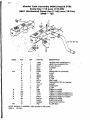
FUEL LIFT PUMP - (ALL N.A. ENGINES)
A - Priming lovor
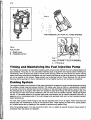
Timing and Maintaining the Fuel Injection Pump
Tho Injoctlon pump delivers on accurately motorod quantity of fuol to each cylinder to suit any engines spood and
load conditions.'Tho pump is a very accurately machined pioco of oqulpmont ond requires careful handling and
maintenance, which is beyond tho scope of normal ownor servicing. Since this pump should not require retiming
oxcopt whon bolng removed ond reinstalled, ond this is boyond tho scopo of normal ownor servicing, tho procedure
will not bo covered In this manual. Please contact your authorized'Lohmon Power distributor lor this sorvlce.
Warranty claims resulting from owner mishandling of tho fuel Injection pump will not normally bo considered.
Cooling System
Your onglne Is coolod by the circulation of frosh water (contalnod In tho system) through the water jackets surrounding
tho cylinders, cylinder hood ond exhaust manifold. Tho heated water flows by thermo- syphonlcoctlon, assisted
by a pump at the Iront of cylinder block around the tubes of a "hoot exchanger" located above the fuel lilt pump on
tho starboard side of the engine. Raw water from outside the boat flows through the heat exchanger tubes, and
tho heat from tho frosh woter is thus transferred to the raw water which Is oxpollod overboard. Please seo Figures
6 ond 9. A Thermostat located In.tho cylinder head under the expansion tank on naturally aspirated units and In a
separate unit on the starboard side of the turbo charged units promotes rapid warm up and maintains constant
onglne temperatures.
The fresh water system Is filled through a cap atop tho expansion tank at front of engine. Water level should be
checked dally ond maintained to the top of the aluminium piller. Those engines are fitted with a cooling system
d o - atration sorvlce and no blooding of the manifold Is required during system tilling.
Whon filling cooling system, fin to top ol aluminium pillar, then run engine for several minutes to insure system Is
completely filled. Add coolant as necessary.
A20
Tho Frosh wator system Is prossurlzod by tho cop atop expansion tank. Whon propor prossuro Is roachod, oxcoss
wator is oxpollod through tho overflow tubo under tank. Extreme core should be taken In removing cap whlio onglne
Is hot. Whilo engine Is hot, II thore Is liquid in tank, the system may be refilled with safety If not, allow onglno to
cool boloro refilling. Lehman Power recommends the use of antl-freezo at ell times used In accordance with tho
manufacturer's recommendations. Ethelyne Glycol basod solutions aro preferred, most ol which Includes various
rust Inhibitors. Tho use of "stop look" typo entl-froozo, which may still be available in somo areas, is discouraged,
if, for some reason antl-lroozo solution is not being used in Iroozlng temperatures, It Is essential that.tho wator
systems bo drained while engine stands idle ond refilled before engine Is restarted. Check water supply daily.
Maintain level to approximately one-half Inch below top of tank - The small "pillar" in the tank should just touch
the water surface.
To assist In corrosion control, a zinc pencil Is Installed In your hoot exchanger. This zinc pencil Is sacrificial.... that
is, tho raw water will attack and "eat away" the zinc before attacking metal ol the hoot exchanger, it Is suggested
that the plug accommodating this pencil be removed each week while engine Is In service In ordor to inspect zinc.
Replace zinc element when required. Failure to Install zincs whon needed may, cause serious damage to entire
cooling circuit.
it will bo noted that: your hoot exchanger has removable ond caps to facilitate cloaning. Removing cops will allow
access to ond of tho tubo "bundle". To clean tubes use a 3/16" diameter wood dowel, with a "twisting" action rathor
than a hammering action. A small caliber firearms cloaning kit or similar small brush may bo used. Do not use a
metal rod which may rupturo the copper tubings.
LEHMAN NATURALLY A8PIRATED ENQINE9
FRE8H & RAW WATER CIRCUITS
_jpb—EST
LEHMAN TURBO INTER C O O LEO
F R E S H A RAW WATER CIRCUITS
)
fv
(NO"*
,k coon?
-
(TURBO - SIMILAR MINUS INTERCOOLER)
_J
mat wktcr
SP275 CIRCUIT
M«»
•»»•
f l i t aw •*<» f±3
tea*
wtffl
A21
FIG. 9. - RAW WATER CIRCULATION SYSTEM
A -^Intake scoop ol standard marlno design, minimum 1" NPT should bo usod lor row wator Inlot. Roduco to Vi"
NPT at pump. Recommended scoop has bars across opening to provont ontry of largo piocos ol forolgn
matter - Lohmon port NO. E W - 3 is porforrod. '
B -
Soo-cock should bo r NPT minimum slzo, "goto" typo opons fully to allow full, unrestricted flow of wator Lehman port NO. E W - 2 2 preferred.
C -
The use of on efficient, full-flow row wator strainer Is strongly rocommonded to prevent clogging ol pump
ond exchangers by weeds, etc. Lehman port NO. EW-102 prolorred.
D -
II hose Is employed for intake, some should bo reinforced type ol extra heavy construction to prevent collapse
under powortul suction of raw water pump - Lehman can provide such hoso II required.
"
Winterization of Cooling System
Inboard type heat exchangers must bo drolnod ol raw wator whon exposed to freezing temperatures. Raw water,
pump, water Inlet piping ond intake strainer should likewise be drained when subjected to extreme cold.
If however, the vossel Is being permanently laid up lor tho duration ol the cold weather, we recommend mixing on
ontl-freeze solution and running this solution through tho sea water system with tho englno Idling until discharged
Irom the exhaust. This Insures tho soa strainer, coolers, heat exchanger, even the muffler and exhaust system will
bo protected.
Drain points for the frosh water system will be found on the port side of oach englno block, on tho aft ond of the
exhaust manifolds and on the heat exchanger.
Raw water drains aro found on both onglne ond transmission coolers, as well as, the heat exchanger. To drain raw
wator pump, loosen roar cover.
"Keel Cooling" Systems
in somo cases tho installation of a "kool cooling" system may bo preferred to tho standard "heat exchanger"
previously discussed. This system employs a series ol tubes mounted on the underside of the hull through which
tho onglne cooling woter Is circulated. Such a system is beneficial when the boat Is to operate In muddy or silt-laden
areas, however, the cooling element does produce additional hull "drag" which could affect performance in faster
boats and creates a potential hazard If tubes fracture or are struck by driftwood, etc.
Piping englno to keel cooler is quite simple. As shown in Fig. 10. the'connection on underside (starboard) of
expansion tank deliver hot wator from onglno to keel coolor. Cooled wator from koel coolor returns to onglne via
connection on aft end of exhaust manifold. Tho use ol 1W l.D. hose will simplify connections, however hoso must
bo reinforced typo to prevent collapsing under suction ond core must be oxerclsod when Installing to avoid "kinks"
or the possibility of chafing.
Installations using a "wofexhoust will roqulred raw water systems as shown In Fig. 9., but omitting heat exchanger.
When dry exhaust is employed, it Is possible to eliminate use of row wator pump. Upon special ordor, lube and
transmission oil coolers of largo size may be Incorporated In the engine Irosh water system. The addition of such
coolers Is shown In Fig. 11.
FIG. 10. FRESH WATER CIRCULATION SYSTEM
(Koel Coolor Typo)
Tokccioooicr
From kool oooior
Lubo oil ooolor
|
To kool ooolor
From kMl ooolor
FIG. 11. WATER CIRCULATION SYSTEM (Keel Coolor Type)
WITH LUBE AND TRANSMISSION OIL COOLERS IN
FRESH WATER FLOW.
A22
Tachometer Adapter
A tachomotor "toko-off" Is provided on tho starboard sldo of all naturally asplrotod engines as an extra cost option.
Thore Is no provision for mechanical tachomotor hook-up on turbochorged engines. This adopter accommodates
a standard marine tachomotor coble with W - 18 adaptor nut. Tip of coblo core should bo .187" diemoter. Cobio
turns on-half onglne spood in counter-clockwise direction.
if mechanical tachometer is not used or if cable Is disconnected with engine to bo oporotod for any lengthy period,
tho take-off should bo copped to prevent oil leakage. Suitable cap (or plug to close operoture if take-off assembly
Is removed) is listed In tho ports section of this manual.
It Is recommended that a mechanical type tachometer be used only If located relatively close to englno. If cable
length exceeds 12 to 14 foot or If many bends ore required, an electrical tachometer system should be considered
as much less strain Is placed upon tho take-off assembly, installations requiring two tachometers should always
use electric instruments.
Electrics
The standard oloctrlcol systom for Lohmon engines is 12 volt, NEGATIVE GROUND. Under no circumstances
should polarity be reversed even for an instant for serious damage to alternator may result.
For spoctoi applications, optional electrical systems oro available In 12 volt insulated return, 24 volt negative ground
ond 24 volt Insulated return configurations.
A voe bolt drives the alternator from crankshaft pulley. (Nolo: maintain bolt at proper tension see "minor Repairs,
Maintenance and Adjustments"). Alternator has boen corrosion-treated and has built-in silicon rectifier and enclosed
slip- ring design for safe, sparkloss, trouble-free operation. Transistor typo, sealed voltage regulator has no moving
parts ond requires no adjustments. Alternator is lubricant packed for life at time of assembly and therefore requires
no external lubrication. All alternators are equipped with a tapping for connection to operate a matching electric
tachometer, (see Fig. 13)
A special actuating switch located on side of engine block behind alternator automatically energizes tho alternator
Irom the battery when onglne Is stortod and oil pressure roaches 7 lbs. Battery Is disconnected by this switch whon
the onglne Is stopped. This switch initiates operation of the alternator systom without the need of a separate switch
and precludes the possibility of tho operator neglecting to turn the charging system on or off. If desired, electrical
instruments such as oil gauge, temperature gauge, etc. may be wired to bo autmoatically energized when onglne
is started.
1
The starter motor is located on the left side (rear) of engine and requires no attention beyond, maintaining the
electric cable connections clean and tight, tho commutator clean and brushes renowed whon necessary.
Tho standard solenoid mounted on the starting motor is a heavy-duty type. It must mechanically engage the starter'
pinion with the ring goar on flywheel thon It must actuate an electric switch to onerglzo the starting motor. As tho
soionold Is normally energized by a simple push-button located at some distance from tho starter, relatively heavy
gouge wire is required to transmit tho needed amperage. Using small gauge wire can result In insufficient current
reaching the startor soionold, overheating of wires, insufficient travel of startor pinion and failure of engine to start.
To assure adequate amperage reaching starter solenoid a "pfggy-back" solenoid Is provided with short, heavy-gouge
wires connecting tho two solenoids. The new solenoid requires comparatively little amperage so smaller gauge
wiring Is required for connection to pushbutton.
.7
.
1
Tho accompanying diagram indicates basic wiring requirements. Make certain that all connections are clean and
tight. Locate battery as close as practical to the starter. Gauge of battery cables will bo dependent upon length,
but should be NO. 0 minimum. Use No. 12 gauge or heavier wire for balance of system. Electrical gauges which
require low current draw may be wired to oil pressure energizing switch Indicated by "X" on the diagram.
A23
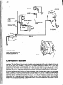
TACHOMETER TAP
Lubrication System
Tho onglno lubricating systom Is ol tho forcod food typo, tho oil bolng circulated by on oil pump mountod with tho
crenkcase. Tho pump draws oil from tho sump through a motal gauzo scroon and through on oil gallory on tho port
(loft) sldo of onglno which Is tapped for Installation of oil pressure gauge, low oil pressure alarm, or othor such
devices. Constant oil pressure is maintained by moons ol a relief valve situated in tho pump. Oil under pressure
passes through the oil filter whore it Is cleaned prior to being circulated Inside tho englno. The filter is o lull-flow,
disposable "spin-on" typo. It should be replaced at each oil change, and is readily available from your Lohmon dealer.
All marine Installations should include on oil pressure gouge to register the lube systom pressure and such gouge
should be frequently checked to insure that systom Is functioning correctly. Normally tho roglsterod pressure should
remain constant for a given engine speed. If pressure reading suddenly varies or fluctuates, tho reason should be
dotorminod ot once, otherwise severe damage may occur. As It Is difficult to maintain a constant watch on onglno
gouges, tho use ol an audible warning systom to sound a buzzer In coso of low oil pressure (or high onglno
tomporaturo) Is strongly rocommondod - Lehman has kits EK31 and EK31A available now fitted as STO In Lohman
panels, - contact your dealer for further details.
A24
Whon onglno lo first installed, provide the proper quantity of oil as Indicated undor "specifications" section. Tho oil
cap Is locatod on top of onglno rockor covor. Aftor pouring in oil. It win bo necessary to wait several minutos boforo
tho oil lovo' is checked In order to allow time for oil to flow to sump. Another fill cop which loads directly to sump
Is located on sump near front of engine. Run engine for several moments, shut down and chock level on dipstick
(see Fig. 14.) if oil level measurement Is different from tho "full" mark on dipstick, a new mark should bo scratched
or filed at tho correct level. Another method Is to measure the distance between tho new full level and tho factory
full mark on the dip stick, remove the dlpstlch tube from tho sump, ond cut that distance off tho tubo. After doburring
ond reinstalling tho tube the dipstick will be lowered into tho oil, thereby retaining the factory markings. Of course,
the above procedure applies only to 6 cylinder N.A. ond turbo units with dlsptlck at front of sump. Four cylinder
models with stick at roar of sump, require scratching tho appropriate marks. Those procedures oro necessitated
by differing Installation angles.
When measuring oil level in regular usage In all naturally aspirated engines It is preferable to check after the engine
has stopped for o period of time, such as overnight. This allows tho oil In tho overhead valve systom to drain back
to tho oil sump, permitting a more accurate measurement.
On all turbochorgod engines tho oil should bo chocked prior to starting. After several minutes, shut onglno down,
wait for oil to drain bock for several minutes, then check and add as required.
Add englno oil of tho typo and viscosity as follows. Oil should meet Ford spoclflcotlbn"2M-2C-iOi7A, API
classification CC or equivalent.
FIG. 15.
OIL VISCOSITY CHART
TURBO ENGINES: API classification CD oils only must bo used In turbochorgod engines. Use of othor oil result
In reduced engine life ond invalidate englno warranty.
Serious damage to turbochorger mo^ result from Inadequate lubrication. Upon stoning, englno should bo allowed
to Idle (1000 rpm maximum) for 30 seconds or more boforo applying load. Also allow engine to Idle for at least two
minutos before shut-down to dissipate hoot from turbochorger bearings.
Turbochargor must bo oll-prlmod under any ono of tho following conditions;
Aftor on oil change.
If oil supply tube to turbochorger has been disconnected,
if either the onglno or turbochargor Is newly installed.
if no oil pressure registers on gouge after a "dead crank" (cranking with stop control In operation) for 15 seconds.
This lest must bo performed If onglno has not been started for 4 weeks or moro.
To oil-prime turbochorger;
a) Check for sufficient oil in tho engine sump but do not top-up at this time.
b) Remove plug on top of turbo oil food block, inject '/« pint of oil and replace plug.
c) Using suitable syringe, Inject about 4 pints of oil (as usod in onglne sump) Into oil gaugo connection for engine.
Refit oil gouge.
d) Stan engine, allowing i minute to Idle boforo Increasing speed.
o) Stop onglno and chock sump oil level. Top-off If needed or drain off any surplus.
A25 t
Englno oil should bo changed oftor (ho initial 15 hours or oporation and at each 200 hours of oporation thereafter.
Run.tho engine until normal operating temperature Is reached. Shut down engine and allow oil to roturn to sump
< for fworto ten minutes, in most Installations It will not be possible to drain sump by removing plug which Is located
at bottom of oil pan, for clearance to bilge of hull will be limited- A low-cost, suction typo, hand operated sump
pump is required. Available as an oxtra cost option Is a Lehman approved, permanently mountod hand pump. This
can bo connected to tho sump lug - Installation permitting or. . . Remove tho dip-stick tubo and Insen suction
hoso of pump, working some towards lower ponion-of sump. (Some operators find it advantageous to uso a length
of copper tubing to assure reaching low section of sump. Pump oil into container and dispose of somo ashore.
Roplaco vent cap on sump. Refill crankcaso to "Mr mark on dlpst/ck. Run onglno for sovoral minutos, shut.down
and rochock oil level. If required, add sufficient oil to bring up to lull mark.
Lube oil flltor oloment should bo replaced at each oil change, the disposable element Is simply unscrewed from Its
baso by turning counter- clockwise on naturally aspirated engines it Is possible to rotate tho oil flltor, or remove it
from Its bracket, thus minimizing the risk of oil spillage. Position a one-quan or larger container under flltor before
removal to catch oil from spilling into bllgo. A new element is simply screwed onto the base with medium hand
tightness. Under no circumstances should a wrench or excess pressure be used. When next stoning engine, chock
filter for possible looks or seepage, and tighten only sufficiently to prevent same.
Transmission
As there is such a wide variety of transmissions available with Lehman diosels, It is not practical to cover oil
Installations In this manual. However, due to tho popularity of the Borg Warnor, PRM/Newage and Twin Disc
transmissions, tho following Information is offered for thoso models.
BORQ WARNER
No attempt Is made heroin to instruct in tho Installation of engine In tho boot. Tho prudent boot ownor or operator
will, boforo initially stoning onglno. chock onglno/shaft alignment, oporato clutch control to make cortaln that levor
fully travels to tho full ahead or full reverse positions, that neutral position may easily and quickly be found and of
course chock oil lovoi.
1
Tho transmission Is a
any kind are requiredassures on adequate
oil temperature which
self-contained, sealed unit with independent lubrication systom. No oxtornal adjustments of
A bulii-ln oil pump supplies the required hydraulic pressure to provide oHortioss shifting and
supply, of lubricant to all moving parts. An oil coolor is provided in ordor to malntoln proper
should not oxcood 190 F .
\\
e
Automatic transmission fluid typo'A, suffix A is recommended' for lubrication*. Or, If doalred, "Doxron" typo fluid
maybe used. Before stoning englno fill transmission to the full mork on the dipstick. Run engine for o minute or
two at low spood (in order to fill oil lines, coolor, etc.) Then shut off onglne end chock oil lovoi. Add sufficient oil to
bring up to full mark. Transmission oil level should bo chocked each time tho oil level in onglno Is chocked. Change
oil every 200 hours of operation or at least once each season under normal conditions howevor, number of hours
may vary depending upon severity and conditions of service WARNER drain plug is a largo "hex" plug located near
bottom right side. Removal of this plug and a small plug on the bottom of tho reduction housing will completely
drain the transmission. On somo models tho coolor return hose may bo fed into tho plug at tho bottom of the
transmission. In those Instances, remove tho hose and rotate the brass elbow as required for draining.
•WARNER WILL NOW ALLOW USE OF SAE 30 OIL
ENSURE YOU CHECK THE STICKER ON THE
COOLER WHICH INFORMS ON TYPE OF INITIAL FILL.
FIG. 16.
WARNING: Onco again wo ropoat... control oablo or othor mochanlom lor shifting transmloo'on must havo ouldclont "throw" to shift iho oporatlng lovor fully Into boih forward or
rovorso position, umoso Qhlti lovor la positively in forward, neutral or rovorso. consldoroblo
damago may rooult. Transmission warranty Is void if control lovor Is changed In any
manner. or foposlHonod o' W Hnttago to romoto control dooo nol novo sulllcioni iravoi tn
both directions.
Whon ordorlng pods for your transmission bo suro to spoclfy boih modol and serial
numbers os shown on identification tag.
\
<
PRM/NEWAQE
Operation
\
A
2
6
V
Flrat tlmo usogo
\ V
Boforo storting tho onolno fill tho goorbox with ono of tho rocommondod lubricants (SAE30W) to tho maximum lovoi
Indicated on tho dipstick.
Ensure that tho goorbox Is In neutral, It Is recommended that tho optional neutral safety start switch (If fitted) should
bo wired In to tho startor circuit to avoid uncontrolled boat movement on stortlng-up. Start up and run tho onolno
and gearbox lor a few minutes to allow the oil to circulate through tho cooling circuit (and angle drive If lifted). Stop
tho onglne, allow to settle, chock tho oil level and 'top-up' to tho maximum level shown on tho dipstick.
Oporotlng tomporoturo
Normal operating temperature should be borwoen 50°C - 70°C with a maximum of 80°C. Tho oil coolers supplied
lor fitting to Newago PRM goarboxes havo adoquato capacity to onsuro correct operating tomporoturo under ail
conditions.
'
Qoar shifting
Newoge PRM marine georboxes have been designed and tested to ensure, rapid shifts Irom. ahead and astern and
vico versa can be operated at lull horsepower ratings and speeds, and the transmission will respond rapidly In
these circumstances. Full power shifts, however, do place abnormal, even II short lived, loads on the goorbox, and
the operating life will be increased If they are reserved for emergency use only.
Trolling (froo-whoollng) tho propbllor.
The bearings used In Newargo PRM gearboxes havo been carefully selected to onsure that prolonged trailing
(froo-whoollng) of tho propeller will not have any detrimental effect on tho transmission. This allows the propeller
to turn (reely with tho onglne shut down and makes Newago PRM gearboxes particularly suited lor use In auxllllary
sailboats, motor sailors, or multi-engine Installations where the boot may bo operated with one or more engines
shut down.
Emorgoncy oporation
included os standard In overy Newago PRM marine goarboxes Is a 'Get-You-Homo' device, allowing tho goorbox
to be mechanically locked In 'ahoad' drive, In the unlikely event ol hydraulic failure. ROUTINE MAINTENANCE
i
Aftor 25 hours running
Drain all oil from tho goorbox and refill with ono of the recommended lubricants. Operate the engine and gearbox,
allowing tho oil to circulate, thon stop tho onglno and allow tho oil to settle. Ro-chock tho oil level and top up if
necessary to the maximum mark on tho dipstick.
Dally
Chock oil level ond make visual chock (or oil leaks especially at the output shaft oil seal and at gasket scaling surfaces.
Annually
Chock oil cooler hosos and connections
Chock propeller shaft alignment
Ensure that remote control operating linkage Is adjusted to give the correct travel on the gearbox operating lovor.
TWIN DISC MARINE TRANSMISSION
All moving parts of the transmission aro lubricated by the oil within the sump os It travels throughout tho hydraulic
system. The oil used should bo of tho same quality and typo recommended for uso In tho engine. Use SAE30 HO
when the Inlet water temperature to the heat oxohangor is above 80°F, and SAE20 Hp whon this temperature Is
below 85°F.
f
Oil lovoi In tho transmission should be checked dally with the onglno at Idle speed and the marine transmission in
"neutraf. Oil lovoi must bo maintained at tho "full" mark on tho dipstick. The period between oil changes isii 000
hours of oporation or 6 months, whichever occurs first. At each oil change the flltor screen, Installed at the bottom
of the roar cover and extending Into the sump, should be removed and cleaned. It should bo re-Installed using pipe
soalant or plpo throad compound on tho threads. The breathor cap should also bo removed and Hushod in cloan
dlesel fuol. Next, disconnect tho hoat exchanger hoses and drain all tho oil from tho hoot exchanger. Finally, If an
oil lllter is used In tho hydraulic system, drain tho filter and connecting hoses, and replace the flltor element.
To drain tho transmission, romovo the Hox-Hoad plug from the bottom of tho moln housing. When re-flillng, use
1.2 US gallons (4.456 its) of oil. Pour tho oil Into the breathor cap opening. After,filling, start tho onglne ond shift
tho unit from "forward" to "roverso" sovorol times to fill the oil lube linos, heat exchanger etc. with oil. Sot tho onglne
at Idlo spood and tho transmission In "neutral". The oil lovoi must be to tho "full" mark on tho dipstick. Ro-lnstal the
broothor cap when tho correct lovoi has boen reached and run tho transmission until the oil tomporoturo has boon
raised to its operating range. Ro-chock tho oil lovoi and top up if necessary.
Periodically Inspect hosos for signs of look, damago or sponglness, replacing' whorb nocossory. Prossuro and
tomporoturo gages should bo regularly Inspected and replaced If found to be damaged or ol suspect accurocy.
II Information on any othor transmission Is roqulrod, please contact Lehman and such Information will bo forwarded
to you.
i
A27
j
,
Maintenance
Tho/lmaortanco ol correct lubrication, periodic Inspection ond adjustment cannot bo over-omphoslzed. On It will
depend, to a very largo extent, tho service which your engine will deliver.
ThoVoal exchanger ol your onglne Is protected by a "zinc pencil" which should be inspected and replaced periodically
os required. As the rate ol electrolysis varies greatly In different areas, only experience will dictate how often
Inspections should bo made.
For convenience lubrication and maintenance work has boon divided into the following periods;
A
B
C
D
Doily
Aftor overy 50 hours running.
Aftor overy 200 hours running.
Aftor overy 1200 hours running.
E After evory 1500 hours running.
F Aftor overy 3000 hours running.
0 After every 3600 hours running.
Summary of Regular Maintenance
Doily
Check onglne and transmission oil levels.
Check oooling wator lovoi.
Check bolt tension and adjust il required.
After first 50 hours of operation
Change Engine Oil ond filter.
Check (exchanger) zinc pencil.'
Check for fuel, lube oil or coolant looks.
Chock all wiring connections, cables, etc.
Check valve clearances, adjust If required.
Evory 200 hours of operation
Change Engine Oil & Filter. And Transmission OH.
Chock Idling spood, adjust If required.
Check exhaust components for leaks.
Check condition of all coolant and oil hosos.
Check all engine mount bolts.
Replace row water pump impollor.
Evory 1200 hours of operation
Flush cooling systom.
Replace anti-freezo.
Evory 1500 hours of operation
Check end ploy of turbochargor rotating assembly.
Evory 3000 hours ol operation
Remove and dismantle turbochorger - repair as required.
Every 3600 hours of oporation
Roploce thermostats.
'Zinc pencil should bo checked every 2 weeks, regardless of number ol operating hours until owner determines
how often zinc olemont must be replaced. Replace after 50% deterioration. .
injectors need not be serviced ot regular intervals but rather, should bo serviced after problem such os smoke, loss
ol power, hard starting, etc. develops and has been, diagnosed.
Minor Repairs, Maintenance and Adjustments
DUE TO REVISED HEAD GASKET, HEAD GASKET AND HEAD BOLT DESIGN RETORQUING OF CYLINDER
HEAD IS NOT REQUIRED. AND MUST NOT B E ATTEMPTED.
TO ADJUST VALVE CLEARANCES: (Note . . . Adjustments should bo mode while engine is at normal operating
tomporoturo). Following removal or rocker arm cover and tightening cylinder head bolts as described above, actuate
tho onglno stop control lover so onglne will not start and rovolvo cronkshalt pulley, until numbers 1 ond 6 valves
(on 4 cylinder, see specification section) or number 1 ond 4 (on 6 cylinder, see specification section) oro opened
by their respective rocker arms.
Insert the correct thickness fooler gouge (as shown in the following table) between the valve stem cop and rocker
arm of No. 3 Inlot valve (on 4 cylinder) or No 9 exhaust valvo (on 6 cylinder) as shown in figure 25. Turn the valve
clearance adjusting screw Fig. 18 until tho feeler blade is lightly caught between the rocker arm and valve stem
cop, but so that tho blade can still be removed with light resistance.
Seloct'the appropriate feeler blade and repeat the procedure for No. 8 exhaust valve (on 4 cylinder) or No. 12
oxhaust valve (on 8 cylinder) models.
\
A28
Rotate tho onglno and following tho soquonco In tho following tablo, adjust oach of tho remaining valves. Replace
rockor covor, making cortaln (hat goskot Is unbrokon ond corroctly positioned. After running englno for o short whllo,
chock rockor arm covor gasket lor possible oil leaks.
\
v
FIG. 18.
ADJUSTING VALVE C L E A R A N C E
1. Adjusting screw
2. Foolor biodo
3. RooKor orm
6 Cylinder engines
4 Cylinder engines
Volvos to Adjust
votvoo Fully Open
1 ond 8
3ond8
1 ond 4
9 find 12
2 ond «
6ond7
Sand 10
3 and 5
3 ond 8
1 ond 8
2ond8
7ondi
8 ond 7
2 ond 4
9 ond 12
Volvos Fully Open
Votvos to Adjust
lond4
3ond3
8ono 10
7ondn
2ond8
TO ADJUST VEE BELT TENSION: Loosen alternator mounting and adjusting strap bolts as per figure 19. Movo
alternator to adjust bolt tension. Tension is correct when your thumb pressure on belt at a point between alternator
or and water pump pulleys does not exceed W . Tighten alternator mounting and adjustment strop bolts:
FIG. 19.
BELT ADJUSTMENT
INTAKE AIR FILTER: Tho air filtering olomont(s) on all naturally aspirated engines Is polyurothano foam which
traps and holds dust and foreign matter which could be drawn Into the englno ond cause severe damage. Turbo
Charged ond Turbo Intorcooled engines only use a Mesh Screen.
By reason of the efficiency ol tho filter In trapping contaminants it Is difficult to offectlvoly clean tho element. It
isusually best to replace this low-cost Horn as occasion demands. Simply slide old element ofl its retaining screen
ond carefully stretch a new element into position, if cleaning Is desired, wash In a mild detergent mixed In clear,
swoot wator. DO NOT wash In mineral spirits, vorsol, gasoline, or any petroleum product.
A29
FIG. 20
INJECTION PUMP (All N.A. ENGINES)
INJECTION PUMP (TURBO ENGINES)
2
1. MQX OpOOO OlOp OCrOW
2. Idling ciop ocrow & lochnut
TO ADJUST IDLING SPEED: Whon proporiy serviced and aftor tho Initial "break-In" porlod, your onglno should
idle as indicated on'spec shoot.
Englno must bo at normal operating tomporoturo whon making adjustments. With onglno running, looson tho idlo
scrow lockout which is on side of fuol injoctlon pump. Adjust tho idle spood screw until olnglnels Idling at correct
spood ond then tighten lockout. Operate the'throttle lever to moke certain that same returns to same sotting.
Note: if onglne Is new or cold, It may idle unevenly. Do not Increase tho Idlo speed setting to compensate. ON NO
ACCOUNT SHOULO THE MAXIMUM SPEED STOP BE CHANGEO.
TO CLEAN FUEL LIFT PUMP Turn off fuel supply valve. Holding receptacle undor pump to prevent spilling of fuol
Into bilge of boot, loosen tho corner bolt ond remove cover ond pulsator. Clean pump thoroughly ond wash covor
ond pulsator in fuel oil. Roploco pons carefully. It will be necessary to bleed fuel systom. Chock for possible looks
after storting onglne. .
'
,
TO CHANGE SECONDARY FUEL FILTERS (note-making certain that tho flltor elemont(s) you win uso is on
EXACT replacement for tho olomont you will remove, otherwise, air leaks into the fuel system may result. Unscrew
tho securing bolts on top of flltor housing ond romovo filter bowls ond elements. Discard elements ond upper ond
lower sealing rings. Wash out the bowls ond clean fuel oil but do not use a cloth for remaining lint may clog tho
fuol eystom. Carefully fit new sealing rings to tho filter heads and bowls, assemble to tho flltor hoods and roploco
and tighten securing bolts. It will now be necessary to bleed the fuel system of air as described In separate section.
After running onglno for a short time, check filters for possible fuel leaks.
Due to tho high temperature of operation a high boiling point antl-froeze Is demanded. Do not ottompt to uso alcohol
or othor non-permanent types and do not use any liquids containing "sealants". Zerex (produced by OuPont) Is
highly recommended. Consult the specification froozo to bring within tho limits of expected temperatures. Inboard
typo hoot exchangers and oil coolers must bo drained of row (sea) wator when exposed to freezing temperatures.
Drain plugs win bo found on bottom of heat oxchangor and oil coolers ond should be removed until all wator has
been drained. Raw water pump may be drained by loosening screws holding rear covor In position. Please refer
to "cooling system" section of this manual for alternate winterizing method.
If boat Is to remain In water while draining onglne, of course, tho intake water seacock must bo closed prior to
draining. Do not neglect to opon sea-cock prior to starting onglne.
NOTE: TO ORAIN FRESH WATER, REMOVE WATER FILLER CAP FROM TOP OF EXPANSION TANK ON
FRONT OF ENGINE. DRAIN BLOCK BY OPENING PETCOCK ON PORT (LEFT) SIDE OF ENGINE IN
CENTER, LOWER SECTION. REMOVE PLUG ON UNDERSIDE OF HEAT EXCHANGER (THE ONE
NEAREST CENTER OF EXCHANGER) TO DRAIN WATER FROM EXCHANGER, EXPANSION TANK AND
EXHAUST MAINFOLO. REPLACE FILL CAP ON TANK AFTER CLOSING PETLOCK AND INSTALLING
PLUG IN HEAT EXCHANGER.
A30
Romov© air Mtor(s) ond covor openings In manifold with plastic film hold in ploco with masking topo. Sool off all
othor openings . . . air vont on top of rockor arm covor, vorjt on front ond of sump and overflow and vont hole,on
Injection pump. Plug exhaust pipe to prevent entrance of moisture.
Make certain that all engine exterior surfaces are clean, dry and free of oil or grease; then spray complete onglno
with any good rust preventative compound.
"
k
Before restarting englno, romovo all plastic seals, covers, oxhaust plug, etc., and refit air flltor(s) in placo. Do not
neglect to replace all drain plugs, tighten roar covor of row wator pump, and turn on seacock.
Galley Hot Water Connections
It is common marine practice to utilize onglno coolant passed through a hot water heater to provide domestic hot
wator. Connection to englno Is mado with Lohman Kit 01496. A coolant food to the heater Is made from the onglno
drain plug on tho portsldo of block while tho coolant roturn hoso is attached to tho forward, port side of the exhaust
manifold. Always ensure that tho max. height of tho cooling hot water coil Is r lower than tho top angle of tho
expansion tank.
SECTION B
PARTS IDENTIFICATION - BASE ENGINE
in ordor to provldo o slmplo mothod ol Identification, all models horoin havo boon assigned a "code" letter as follows.
ENGINE CODE
M-Supor 90
N-Suporl35
For
0080
CU/IN
254
360
NO. CYLS.
4
6
YEARS
6/62- '
6/62t
• ENGINE CODE
S-SuporSPl65
P-Supor 225
' T-SuporSP275
CU/IN
363
363
363
NO. CYLS. YEARS
6
9/65, 6
6/62-6
, 9/65j
In locating part numbers, turn to tho applicable page:
Bearings, main and rod
Block, onglno
Camshaft
Crankshaft
Dampor. crankshaft
Flltor, fuol
Flywhool
Gaskot kit, onglno
Hood, cyllndor
Injoctlon oqulpmont:
Injoctors
Plpos
Pump
Pistons
Pulloys, crankshaft
Pump, fuol (lift) . '.
Pump, oil
Pump, wator
Storting motor
Sump (oil pan)
Tools
Turbochargor
Volvos
I
. . . .
1
.
.
B4.B5.B6
B2.B3
B7
B4.B5.B6
B12
B17
SoctSoctC
B2
B6
,
B14
B14
B13
B5.B6
B12
B15.B16
B16.B19
B23
B24.B25
B21.B22
B1 SooSoctC
B9
By reference to tho drawings on tho applicable page, select tho roqulrod part and noto tho "key" number assigned
to It. The key number will bo repeated In the first column of a following page. The second column will indicate the
onglne to which tho port applies per tho onglne code letters shown above. Tho third column shows tho required
per englno.
Service Tools
6A1
WRENCH FOR FUEL INJECTION PIPE NUTS (TOP OF INJECTION PUMP)
6A2
SOCKET TOOL - DELIVERY VALVE HOLDER
6A6
TAPPET WRENCH-FLEX FUEL LINE to LIFT PUMP (NOT SHOWN)
6A7
TIMING TOOL (23-507)
B2
KEY
ENGINE
QTY
PART No.
DESCRIPTION
1
M
N
P/S/T
M
N
1
1
1
1
1
6062059
6066760
6079407
6134949
6134954
6134959
6103612
6134967
6134960
1620146
6134956
6134960
6134952
6134954
6134953
6104236
610423d
6104237
BLOCK ASSEMBLY
,
BLOCK ASSEMBLY
BLOCK ASSEMBLY
GASKET KIT (OVERHAUL)
GASKET KIT (OVERHAUL)
(B)
(B)
GASKETKIT (OVERHAUL)
(B)
GASKETKIT(ENGINE DE-CARBONISING)
GASKET KIT (ENGINE DE-CARBONISING)
GASKET KIT (OIL PAN & FRONT COVER)
GASKET KIT (OIL PAN & FRONTCOVER)
GASKET KIT (OIL PAN & FRONT COVER)
GASKET KIT (OIL PAN)
GASKETKIT(OILPAN)
GASKETKIT (OILPAN)
(A)
(A)
(A)
(A)
(A)
(A)
(A)
(A)
P/S/T
M
P/S/T
M
N
P/S/T
M
N
P/S/T
(A) HEAD GASKET NOT INCLUDED MUST BE ORDERED SEPARATELY.
(B) NOT SHOWN.
REMARKS
B3
KEY
ENGINE
QTY
1
M
N ,
P/S/T
P/S/T
1
1
1
6
6
8
6
6
1
1
3
3
A/R
1
1
2
4
P/S/T
P/S/T
P/S/T
ALL
ALL
ALL
5
6
7
8
ALL
ALL
ALL
ALL
3
9 ;
10"
11
12
13
ALL
M
N
P/S/T
ALL
ALL
ALL
J
•
PARTNo
6086757
6088760
8066760
6077156
6128842
6139765
6139766
6139768
" 1788926
1788931
6046528
6046527
6102931
, 6107196
1786927
1503090
'
2' '•'
10/14''
10/4
10/14
2
1
'
h
1551172
1786352
1788352
1786352
6149422
6086763
1485471
REMARKS
CYLBLOCK
CYLBLOCK
CYLBLOCK
„..,};
CYLLINER4.289"4.290"
REFER TO
CYL LINER 4.29r4.292TECH BULLETIN'
CYLUNER4.269 4.290"
66/03
CYLLINER4.290 4.291"
BLOCK CODES
'CYL LINER 4.291"4.292CAMBEARING2.33-2.31
CAM BEARING 2.35-2.33
FREEZE PLUG-2.16"
FREEZE PLUG -2.20"
FREEZE P L U G - 1.660"
DISTRIBUTOR APERTURE
TAPPET OIL GALLERY
OIL GALLERY PLUG
rt
;
OIL GALLERY PLUG ' '
CRANK SHAFT BEARING CAP BOLT
CRANK SHAFT BEARING CAP BOLT
CRANK SHAFT BEARING CAP BOLT
PIN
PARTOF BLOCK ASSEMBLY
WATER DRAIN FAUCET
10/61-11/82
10/61-11/82
11/82
11/82
11/62
B4
KEY -
ENGINE
1
2
;
QTY
M
M
N
N
P/S/T
'M
N/P/S/T
M
N/P/S/T
N/P/S/T
M
N/P/S/T
M
N/P/S/T
3
ALL
ALL
ALL
ALL
-
ALL
*ALL
For footnotes turn to pago 86
PARTNo.;„,DE8CRIPTION
, 6077423, CRANKSHAFT
CRANKSHAFT
1608855
/CRANKSHAFT
,6077425
CRANKSHAFT
8119349
1608158 '•CRANKSHAFT
6106301 • -CRANKSHAFT MAIN BEARING SET
•CRANKSHAFT MAIN BEARING SET
6106302
6106222 , -CRANKSHAFT MAIN BEARING SET
•CRANKSHAFT MAIN BEARING SET
6108225
:6108228< •-CRANKSHAFT MAIN BEARING SET
6106232 . • CRANKSHAFT MAIN BEARING SET
6108305 /CRANKSHAFT MAIN BEARING SET
6108308 ; /CRANKSHAFT MAIN BEARING SET
CRANKSHAFT MAIN BEARING SET
6106311.
CRANKSHAFT MAIN BEARING SET
610631.4
CRANKSHAFT THRUSTWASHER
8106285
8108288
6108287'
CRANKSHAFT THRUST WASHER
6106288
6106269
CRANKSHAFT THRUSTWASHER
8108290
6106291
.CRANKSHAFT THRUST WASHER
6106292
I r
'
6106293
CRANKSHAFTTHRUSTWASHER
6106294
6106295
'CRANKSHAFT THRUSTWASHER
6106296
REMARKS
•(A)
(B)
(A)
i(B)
STD
-.010
-.010
• ' -.020
-.020
'-.030
• '-.030
,' '-.040
-.040
• STD
(
'
+.0025
i
+.005
+ .0075
+.010
• +.015
B5
KEY
' ENGINE
3
ALL
j
4
5
6
ALL
ALL
ALL
7
M
N
P/S/T
' M/N
M/N
M/N
M/N
P/S/T
M/N
M/N
M/N
M/N
P/S/T
M/N
P/S/T
M/N
M/N
M/N
M/N
P/S/T
P/S/T
P/S/T
P/S/T
6
9
10
11
QTY
PART No.
6108297 '
610629ft.
1
8153760'
1
8090885
1
1599715
1599714
1599713
4
6143195
6
8143195
6
8100051
4/8
6143196
8143197
4/8
4/6
' 6143198
6143211
4/6
1599879
6
4/6 •
6143212
6143213
4/8
'
8143214
4/8
8077162
4/8
6
* 6077183
6/12
1415288
12
6077164'
6088942
4/6
6088943
4/6
6088944
4/6
4/8
'8088945
6
8066946
6
6086947
6
6066948
8
6088949
1
For footnotes turn to pago 86
DESCRIPTION
J
CRANKSHAFT THRUST WASHER
CRANKSHAFT OIL SEAL
WOODRUFF KEY
CRANKSHAFT GEAR
CRANKSHAFT GEAR
CRANKSHAFT GEAR
PISTON, PIN, RING ASSEMBLY
PISTON, PIN, RING ASSEMBLY '
PISTON, PIN, RING ASSEMBLY
PISTON, PIN, RING ASSEMBLY
PISTON, PIN, RING ASSEMBLY
PISTON. PIN. RING ASSEMBLY
PISTON RING KIT
PISTON RING KIT
PISTON RING KIT
PISTON RING KIT
PISTON RING KIT
PISTON PIN
'PISTON PIN
SNAP RING
SNAP RING
CONNECTING ROD
CONNECTING ROD
CONNECTING ROD
CONNECTING ROD
CONNECTING ROD "
CONNECTING ROD
CONNECTING ROD
CONNECTING ROD
REMARKS
+.020
(C)BLUE
"(D) Y E L
(E)'RED
STD,
STD,
STD,
+.015
+.035
+.055
' STD.
STD.
+.015
+ .035
+ .055
STD.(AAB)
.003 (ABB)
.006 (ACB)
.009 (ADB)
STD. (GAB)
.003 (GBB)
.006 (GCB)
.009 (GOB)
B6
KEY
ENGINE
QTY
12
M/N
P/S/T
ALL
ALL
M/N/P/S/T
P/S/T
M/N/P/S/T
p/s/r
M/N
P/S/T
P/S/T
M/N/P/S/T
P/S/T
M,N
P/S/T
4/8
6
6/12
6/12
8/12
6
8/12
6
8/12
6
6
8/12
6
8/12
6
6
6
6
13
14
16
•
17
18
ALL
ALL
(A) TO BE USED
(B) TO BE USED
(C) TO BE USED
(D) TO BE USED
(E) TO BE USED
(
PART No.
DESCRIPTION
1497464
CONNECTING
BUSHING
8078059
1447824
BOLTS
1428387
PIN
6101141
CONNECTING
8101142
CONNECTING
6101143
CONNECTING
CONNECTING
6106203
CONNECTING
6106200
CONNECTING
' 6105860
CONNECTING
6105658
6105657
CONNECTING
CONNECTING
6106205
6106202
CONNECTING
6105662
CONNECTING
6108202
CONNECTING
- 1599712 , -NOZZLE
1541955; ,SEAL
IN ENGINE WITH GREEN DATA PLATE
IN ENGINE WITH LIGHT BLUE DATA PLATE
WITH 6103310 CAMSHAFT GEAR
WITH 6103311 CAMSHAFT GEAR
WITH 6103312 CAMSHAFT GEAR
REMARKS
ROD
.*.'/
ROD BEARINGS
ROD BEARINGS
ROD BEARINGS
ROD BEARINGS r
ROD BEARINGS
ROD BEARINGS'
ROD BEARINGS
ROD BEARINGS
ROD BEARINGS
ROD BEARINGS
ROD BEARINGS
ROD BEARINGS
STD.
STD.UPPER
-.010
-.010 UPPER
' -.020
-.020 UPPER
-.020 LOWER
-.030
-.030 LOWER
-.040
-.040 LOWER
-.040 UPPER
B7
KEY
1
2
3
4
5
6
7
6
9
10
11
12
13
ENGINE
'
QTY
M
M
N
N
P/S/T
1
1
1
1
1
•' ' ALL
" ALL
ALL
ALL
ALL
ALL
ALL
ALL
ALL
ALL
ALL
ALL
ALL
ALL
ALL
ALL
1
1
3/5
3/5
1
1
1
3
3
1
1
1
1
1
1
1
PART No.
DESCRIPTION
6112042
CAMSHAFT
6129243
CAMSHAFT
' 6112043
CAMSHAFT
V6129244
CAMSHAFT
^6112044
CAMSHAFT
CAMSHAFT
'6129245'
1794742 ' FRONT CAMSHAFT BEARING STD
" 1794743
FRONT CAMSHAFT BEARING +0.020
1789333
CAMSHAFT BEARING STD
1789334
CAMSHAFT BEARING +.020
1427085
CAMSHAFT THRUST WASHER
6141685
PLATE CAMSHAFT THRUST
,
1702841
LOCKING NUT , '
1586492 ' BOLT
1575329
WASHER
1793896
THRUSTWASHER " " .
1614696
GEAR CAMSHAFT"
6103311
GEAR CAMSHAFT
GEAR CAMSHAFT
6103312
KEY
8142815
BOLT
1467140
CAP
1446566
REMARKS
'
1061-0962
'09621081-0962
09621061-0962
0962
1
1
BLUE
YELLOW
RED
Be
KEY
ENGINE
QTY
PART No.
1
M
N
P/S/T
M
N
P/S/T
ALL
M/N
P/S/T
ALL
ALL
M/N/P/S/T
ALL
ALL
ALL
ALL
P/S/T
M
N
M/N/P/S/T
M
N/P/S/T
ALL
M/N
1
1
1
1
1
1
1
1
1
1
17/25
1
4/8
4/8
4/8
4/8
1
1
1
8082577
8082576
6062579
6103811
6103813
8139784
1786821"
1790851
6077317
1448568
8103719
2C311
1430247
1430246
1430249
1430250
1F55
1F58
1F56
1F57
6102582
8102563
1798508
1548074
2
3
4
8
7
6
9
10
11
12
13
14
15
e/e
1
1
4/6
1
>V
!
DESCRIPTION
CYLINDER HEAO
CYLINDER HEAD
CYLINDER HEAD '
HEAD GASKET
HEAD GASKET
HEAD GASKET
DOWEL
DOWEL
'
'
.DOWEL
PLUG
BOLT .
CAP (CHROMED) '
INLET VALVE SEAT STD
INLET VALVE SEAT + .010
EXHAUST VALVE SEAT STD
EXHAUST VALVE SEAT + .010
VALVE COVER (CHROMED)
VALVE COVER (CHROMED)
VALVE COVER (CHROMED)
S C R E W (CHROMED)
GASKET
GASKET
'SLEEVE
VALVE
1
REMARKS
B9
1
2
3
6
8
1
22 26
Pago B8
Itoma 9, 10
KEY
ENGINE
QTY
1
M
N/P/S/T
ALL
ALL
ALL
ALL
ALL
ALL
ALL
ALL
ALL
ALL
ALL
ALL
ALL
ALL
ALL
ALL
ALL
ALL
ALL
ALL
ALL
ALL
ALL
ALL
ALL
M/N
P/S/T
ALL
ALL
ALL
ALL
1
2
2/4
2/4
2
2
2/4
1
5/7
5/7
4/8
4/8
4/8
8/12
8/12
8/12
8/12
8/12
4/6
4/6
4/6
4/8
8/12
4/6
4/6
8/12
8/12
4/6
6
4/8
16/24
8/12
8/12
2
3
4
5
6
7
8
9
10
11
12
13
14
15
18
17
18
19
20
21
22
23
24
25
PART No. _ DESCRIPTION
1788686
6085981
6089062
1602472
3418839
6116096
6093816
6093819
1608753
1575329
1745333
6084185
6064186
6079714
6118749
6125498
6086868
1504134
6093966
6133062
6093969,
8133084
1789728
1542862
1717773
1710777
6089268
8101533
1598817
1598817
1473015
8093972
1789727
i.
ROCKER ARM SHAFT
ROCKER ARM SHAFT
WASHER
BOLT
PLUG
ARM SUPPORT
ARM SUPPORT •
ARM SUPPORT
BOLT
LOCK WASHER
SPRING
LEFT HAND ARM
RIGHT HAND ARM
VALVETAPPET
VALVETAPPET
VALVETAPPET
ROD
SCREW
VALVE (EX)
VALVE (EX)
VALVE (IN)
VALVE (IN)
VALVE SPRING CAP
SPRING EXHAUST
SPRING INLET '
VALVE GUIDE STD.
VALVE GUIDE O/S ,
SEAL VALVE STEM (IN)
SEAL VALVE STEM (IN)
SEAL VALVE STEM (EX)
RETAINER
COLLET
CAP
REMARKS
10/81-4/82
5/82-11/82
11/82-
10/81-1/83
1/6310/81-1/83
1/83-
B10
KEY
ENGINE
QTY
1
M,N
P/S/T
M,N
P/S/T
M,N
P/S/T
ALL
M,N
P/S/T
ALL
ALL
ALL
ALL
ALL
ALL
1
1
1
1
1
1
1
1
1
1
1
1
1
1
1
2
3
4
5
6
7
8
9
10
PART No.
DESCRIPTION
6113977
TIMING GEAR HOUSING
8113978
TIMING GEAR HOUSING
8102580
GASKET
1599788
GASKET
6105291
COVER
6105292
COVER 1599717
COVER
8102581
GASKET.
1599789
GASKET
6108640
SEAL
1599790
SPACER
6102559
SEAL
1419959
SLEEVE STD.
1419980 > SLEEVE.020O/S
1769541
PLUG '
REMARKS
B11
14,18,18,17,1820,21-
I
KEY
ENGINE
QTY
PART No.
DESCRIPTION
11
12
13
14
15
16
17
18
19
20
21
22
ALL
ALL
ALL
ALL
ALL
ALL
ALL
ALL
ALL
ALL
ALL
ALL
A/R
A/R
A/R
A/R
A/R
A/R
A/R
A/R
A/R
A/R
A/R
A/R
1506431
1566867
0241729
1571467
1579207
1575027
1584241
1602500
1579329
1444685
1436268 '
1459510
BOLT
BOLT
BOLT
BOLT
BOLT
BOLT
BOLT
BOLT
WASHER FLAT
WASHER FLAT
WASHER FLAT
LOCK WASHER
(g)
REMARKS
B12
SUPER 90
SUPER 135
SUPER 185/225/275
r
KEY
ENGINE
QTY
PART No.
DESCRIPTION
1
2
4
5
6
8
9
10
11
12
13
14
15
18
17
18
19
20
21
M
M
M
N
N
P/S/T
M
M/N
M
M
M
M
P/S/T
P/S/T
P/S/T
P/S/T
P/S/T
P/S/T
P/S/T
1
1
1
1
1
1
1
1
4
2
2
4
1
1
1
1
1
1
4
6091907
6088402
6091906
1817390
6091908
6119026
'1409531
6059090
1575330
1588477
1760723
1444685
6090806
6090886
6090808
6090807
6090883
6090884
1489492
PULLEY
-PULLEY ,
SPACER
SPACER
PULLEY
PULLEY
HUBASSEMBLY
BOLTASSEMBLY
BOLT
BOLT
WASHER FLAT
WASHER FLATWASHER (CRANKSHAFT DAMPER)
WASHER ASSEMBLY (DAMPER LOCKING)
BOLT '
HUB (CRANKSHAFT PULLEY)
ORING
ORING
BOLT
OCCASSIONALLY CUSTOMERS UTILISE VARIATIONS ON PULLEYS - IF IN DOUBT CONSULT YOUR LEHMAN
DEALER OR LEHMAN DIRECT
KEY
ENGINE
1
1
1A
1A
2
3
4
5
6
7
M
N
T
P/S
ALL
ALL
ALL
ALL
ALL
M,N,
P/S/T
ALL
ALL
ALL
ALL
ALL
ALL
e
9
10
12
13
14
QTY
V
1
1
1
1
1
1
1
1
1
1
1
1
1
PART No.
6108557
6108582
2C500
8108567
1575271
6062230
1415684
1575009
1719874
6077521
6114477
6077523
6057435
6108572
8104804
6145170
2E807
DESCRIPTION
FUEL INJECTION PUMP
FUEL INJECTION PUMP
FUEL INJECTION PUMP
FUEL INJECTION PUMP
BOLT
STUD
WASHER
NUT
\ SEAL, RING
jGEAR
GEAR
PLATE
BOLT
OILTUBE
BLEED VALVE
cAv NUT 6086937
EXCESSFUELSOLENOI
NOTE:- SP275 ONLY, FUEL INJECTION PUMP IS 2C500/S
REMARKS
9 10 7 9 10
•A
DESCRIPTION
KEY
ENGINE
QTY
PART No.
1
2
3
4
1
2
3
4
5
6
7
6
9
10
11
12
M
M
M
M
N/P/S/T
N/P/S/T
N/P/S/T
N/P/S/T
N/P/S/T
N/P/S/T
ALL
ALL
ALL
ALL
ALL
M
N/P/S/T
ALL
ALL
P/S/T
M/N
ALL
ALL
ALL
ALL
ALL
M/N
P/S/T
ALL
1
1
1
1
1
1
1
1
1
1
A/R
A/R
A/R
A/R
A/R
1
1
1
1
6
4/6
A/R
A/R
A/R
A/R
A/R
4/6
6
1
No. 11NJECTION LINE
6105606
6105807
No. 2 INJECTION LINE
No. 3 INJECTION LINE
6105608
8105609
No. 4 INJECTION LINE
8097946
No.1 INJECTION LINE
8097949
No. 2 INJECTION LINE
No. 3 INJECTION LINE
6098078
No. 4 INJECTION LINE
8097950
No. 5 INJECTION LINE
6098081
8098062'}' No. 6 INJECTION LINE
1514329
LINE CLAMPS
LINE CLAMPS
1514330
SCREW
1572059
LOCK WASHER
8029099
1802234
FERRULE
6113157
.LEAKOFFPIPE
LEAK OFF PIPE
6113158
1461753
CONNECTOR
1514322
CONNECTOR
6141344
NOZZLE
6141341
NOZZLE
1828181
BOLT
6114632
SEAL
1605353
SEAL
NUT
1791101
1707224
WASHER
INJECTOR ASSY
6108589
INJECTOR ASSY
1599947
BOLT'
1828011
13
14
15
15A
16
17
16
19
20
21
21A
22A
REMARKS
Noto: SP275 only (or modified Injoctor assy with pro sot test pressure call for Lohman Part 2C502/S.
1
K
B15
;
/
f
KEY
ENGINE
QTY
1
2
3
4
5
6
7
8
9
10
11
12
13
14
15
18
17
18
19
20
M/N
M/N
M/N
M/N
M/N
M/N
M/N
M/N
M/N
M/N
M/N
M/N
M/N
M/N
M/N
M/N
M/N
M/N
M/N
M/N
1
2
2
1
1
1
1
1
1
1
1
2
2
8
8
2
1
1
1
1
PART No.
DESCRIPTION
8038718
FUEL PUMP
8115328
STUD
NUT
1582108
1459154
PLATE
GASKET
1789438
2703732
ARM
1491104
'ARM
1749177
PIN
1749182
SPRING
DIAPHRAM ASSEMBLY
8039026
8039027
SPRING
GASKET''
1749081
1708711
VALVE ASSEMBLY
BOLT '
1472222
1757975
WASHER
1791854
DIAPRAM
1749047
COVER
1405313
SPRING
1583808 * KIT
EI8017
FUEL LINE 22"
REMARKS
81
KEY
ENGINE
1
2
3
4
5
10
12
P/S/T
P/S/T
P/S/T
P/S/T
P/S/T
P/S/T
QTY
PART No.
8144640
1789438
8115328
,1444885
1566200
1502536
1503662
DESCRIPTION
REMARKS
PUMP
GASKET
STUD
WASHER
NUT
BANJO BOLT
WASHER
\ )
10
•
T
•
KEY
ENGINE
QTY
PART NO.
DESCRIPTION
REMARKS
1
2
3
4
5
6
7
6
9
10
11
12
13
P/S/T
P/S/T
P/S/T
P/S/T
P/S/T
P/S/T
P/S/T
P/S/T
P/S/T
P/S/T
P/S/T
P/S/T
P/S/T
1
2
2
2
3
3
1
1
1
1
2
3
1
1538780
1472081
1459510
1598717
1596719
8115328
1444866'
1588200
1789438
1501898
1501527
1503662
8005925
PUMP
BOLT •
WASHER
PLUNGER
ADAPTOR
STUD
LOCK WASHER
NUT
GASKET
GASKET
ADAPTOR
WASHER
WASHER
FILTER
ASSEMBLY
PART No.
8035906
For P/S/T only
(not shown)
KEY
ENGINE
QTY
PART No.
1
2
3
4
5
6
7
ALL
ALL
ALL
ALL
ALL
ALL
ALL
ALL
ALL
ALL
ALL
ALL
ALL
ALL
M/N
P/S/T
M
' N
P/S/T
ALL
P/S/T
P/S/T
ALL
ALL
ALL
1
2
4
2
2
1
2
2
2
2
4
4
1
1
1
1
1
1 .
1
A/R
1
1
2
1
1
6069149
6148717
1422403
1760894
3416157
6119122
0201029
1568867
6069626
8034917
1451781
1465503
1419562
1548391
3K776
3K793
6109560
8109561
3K781
8107558
6104604
6145169
1502687
FH93
1579367
e
9
10
11
12
13
14
15
16
17
18
19
20
21
22
DESCRIPTION
FUEL FILTER ASSEMBLY
FUEL FILTER ELEMENTS
SEAL
WASHER
WASHER
BRACKET
STUD
BOLT
BUSH
SEAL
FLAT WASHER
NUT
SCREW
, WASHER .
TUBEASSEMBLY
TUBEASSEMBLY
TUBEASSEMBLY
TUBEASSEMBLY
TUBEASSEMBLY
PLUG
VALVE ASSEMBLY
STR HOSE FITTING
PLUG
HEADER BRACKET
BOLT
REMARKS
10-61/05-02
1
KEY
1
2
3
4
5
6
7.
6
9
10
ENGINE
M/N
M/N
M/N
M/N
M/N
M/N
M/N
M/N
M/N
M/N
M/N
M/N
" M/N
M/N
M/N
M/N
(A) HOLBOURN EATON
<B) WHITEHEAD
QTY
1
1
2
2
1
1
1
1
1
1
1
1
1
1
1
1
DESCRIPTION
PART No.
OILPUMP
6100762
'
6100763 ' OILPUMP
BOLT
1566669
LOCK WASHER
1560616
ROTOR & SHAFT
6105323
6106324
ROTOR & SHAFT
GEAR
1793668
GEAR
1606369
1606367
SPRING PIN
SPRING PIN
1606366
1605121
PLUNGER
PLUNGER
8106331
6106326
SPRING
6106329
SPRING '
CAP
6106336
PIN
1433211
1
1
REMARKS
(A)
(B)
(A)
(B)
(A)
(B)
(A)
(B)
(A)
(B)
(A)
(B)
(A)
(A)
B19
KEY
ENGINE
1
2
3
4
5
i
6
7
6
9
10
11
12
t
QTY
PART No.
1
1
2
1
1
1
1
1
1
1
1
1
1
3
3
1
1
(A)6100766
(B)6100767
1602210
(A)6106326
(B)6106326
(A)6106327
(AJ160512V
(B)6106331
(A)6106326
(B)6106330
(A)6106336
<B)6106337
1602162
1569164
1444665
6103491
6069943
(A) HOLBOURN EATON
(B) WHITEHEAD MOTORIDES
DESCRIPTION
REMARKS
PUMP ASSEMBLY
PUMP ASSEMBLY
STUD '
ROTOR & SHAFT ASSEMBLY
ROTOR & SHAFT ASSEMBLY
THRUSTPLATE
PLUNGER (RELIEF VALVE)
PLUNGER (RELIEF VALVE)
SPRING
SPRING
CAP
CAP ,
GASKET •
BOLTLOCK WASHER
TUBEASSEMBLY
•
FLANGE
SP185/225/275
SP185/225/275
SP185/SP225/SP275
SP185/SP225/SP275
SP165/SP255/SP275
SP165/SP225/SP275
B20
KEY
ENGINE
QTY
PART No.
DESCRIPTION
1
2
3
4
5
6
7
6
9
10
P/S/T
P/S/T
P/S/T
P/S/T
P/S/T
P/S/T
P/S/T
P/S/T
P/S/T
P/S/T
1
2
1
4
1
1
1
3
1
t
6121147
6103660
6106606
1502640
8103879
6103620
6103660
OE407.5
1612468
8121713
ADAPTOR OIL FILTER
CONNECTOR
CONNECTOR
BALL
PLUG
WASHER
90 ELBOW
BOLTS
OIL FILTER
GASKET
REMARKS
N.B. A REMOTE MOUNTING IS AVAILABLE FOR THIS FILTER ASSEMBLY NUMBER 0197R (1 motor) D197R-2
(2 motor) CONTACT YOUR DEALER.
B21
KEY
ENGINE
1
N
P/S/T
N
P/S/T
ALL
ALL
ALL
ALL
• ALL
ALL
ALL
ALL
N
P/S/T
ALL
ALL
N
P/S/T
N
P/S/T
ALL
ALL
ALL
ALL
ALL
ALL
ALL
ALL
ALL
ALL
ALL
2
3
4
5
6
6A
7
7A
8
9
10
11
4
12
13
14
15
16
17
17A
16
19
20
21
21A
Whon pump out kit fitted
QTY
1
" '
1
1
1
1 '!
1
1
1
1
•
1
1
1
1
1
1
1
1
1
1
4
A/R
4
A/R
1
1
1
1
1
1
PART No.
DESCRIPTION
1403431
8108334
6104236
6104237
1411447
1411446
1608307
1708046
1710927
OGC50
1595292
3E883
1508092
6087662
1538040
1477027
1768795
6097106
1403432
6090988
1401461
6113951
1575009
1566479
1A239
1C28
OC31
OE201
OE290
1703791
1759501
OIL PAN
OIL PAN
GASKET KITOIL PAN
GASKET KIT OILPAN
TUBE ,
TUBE
CAP ASSEMBLY
INSERT DRAIN PLUG
WASHER
WASHERPLUG OIL DRAIN
BANJO BOLT'
OIL PUMP PICK UP TUBE & S C R E E N
OIL RUMP PICK UP TUBE & S C R E E N
BOLT
WASHER
TUBESHORT
TUBE LONG
DIPSTICK
DIPSTICK
STUD
WASHERLOCK
NUT
BOLT
COVER APERTURE
COVER APERTURE GASKET
LOCKWASHER
BOLT
PLUG ASSEMBLY
PLUG HEX
WASHER FLAT
REMARKS
STD
O/S
B22
KEY
ENGINE
QTY
1
2
3
M
M
ALL
ALL
ALL
ALL
ALL
ALL
ALL
ALL
M
ALL
ALL
M
M
ALL
ALL
ALL
ALL
ALL
ALL
ALL
ALL
ALL
1
1
1
1
1
1
1
4
5
6
6A
7
7A
6
9
10
11
12
13
14
15
16
17
17A
16
19
20
1
1
1
1
1
1
1
4
A/R
4
A/R
1
1
1
1
1
PART No. i DESCRIPTION
1509694
6104236
1411447
1411446
1608307
1708046
1710927
OGC50
1595292
3E668
1508086
1538040
1580816
1788795
1791936
1401461
6113951
1575009
1566479
1A239
1C26
OC31
OE201
OE290
REMARKS
1
OIL'PAN
*
GASKET KIT OIL PAN
TUBE '
\ CoroPlugPP065(
TUBE
I may bo
CAP ASSEMBLY J substituted'
INSERT DRAIN PLUG
WASHER
WASHER*
PLUG OIL DRAIN
BANJO BOLTOIL PUMP PICK UP TUBE & SCREEN
BOLT
WASHER
TUBE
DIPSTICK'
STUD
WASHER, LOCK
NUT
BOLT
COVER APERTURE
COVER APERTURE GASKET
LOCKWASHER
BOLT
PLUG ASSEMBLY
' Whon pump out kit flttod
N.B. HIGH LEVEL OIL PAN AVAILABLE ON SP165/225/275. PART No. D900T.
STD
O/S
1
•via
>
B23
KEY
6
7
6
9
10
11
12
13
14
15
16
16
19
20
ENGINE
QTY
PART No.
M/N
P/S/T
ALL
ALL
ALL
, ALL
ALL
ALL
ALL
ALL
ALL
1
1
A/R
A/R
A/R
A/R
A/R
A/R
A/R
A/R
2
A/R
1
A/R
1
1
1
1
1
1
1
1
1
1
A/R
1
1
1
1602421
WATER PUMP
6089346
WATER PUMP
1571467
5/16/.75BOLT
1568491
5/16/1.0 BOLT
1568469 . 5/16/1.0 BOLT
1568469
5/18/1.25 BOLT
1564477
5/16/1.75 BOLT
1572232
5/16/2.25BOLT
1602361
5/18/3.50 BOLT
1405658
5/16 / 4.00 BOLT
6118463
5/16/1.77" STUD
6115325
5/l6/2.79"STUD
6102970
5/l6/2.63"STUD
1575209
NUT,
6091842
GASKET WATER
6094370
GASKET WATER
1802430
IMPELLER
8077199
IMPELLER
6086162
SEAL
6077206
BACK PLATE
3K631
CAP
3K827
CAP
1602434 . BEARINGS SHAFT
6077200,
BEARING & SHAFT
OC31
LOCK WASHER .
6089351
DUALSHEAVE PULLEY
1711744
PULLEY
1602440
HUB
ALL
M/N
P/S/T
M/N
P/S/T
ALL
P/S/T
N/M
P/S/T
N/M
P/S/T
ALL
P/S/T
M/N
M/N
-
DESCRIPTION
N.B. M/N 1 Wator pump ropalr kit - Horns 7,9,11 & 14.
P/S/T 1 wator pump ropolr kit - Itoms 8.10.11 & 15.
REMARKS
B24
In Lohmon Wiring
Harness thoro 19 o
email Coppor Fu90
Port No. 2E612
Fitted In Lino
to Solenoid
A - 6 - Hardware Kit
• - 34 - Motor'Soellng Kit
KEY
ENGINE
QTY
PART No.
1
2
3
5
6
7
8
9
10
11
12
13
14
15
16
17
18
19
20
M/N
M/N
M/N
M/N
M/N
M/N
M/N
M/N
M/N
M/N
M/N
M/N
M/N
M/N
M/N
M/N
M/N
M/N
M/N
1
3
3
1
1
1
1
1
1
1
1
1
1
1
1
1
1
1
1
6092295
1805123
1451761
1527447
1470620
8104802
1517314
1596362
1517316
1517315
1527241
1596361
1522092
1517313
1527442
1517321
1522094
1527444
1517318
DESCRIPTION
STARTER MOTOR
BOLT
FLAT WASHER
SOLENOID ASSEMBLY
ARMATURE ASSEMBLY
BOLT
HARDWARE (KIT)
DRIVE HOUSING (KIT)
SOLENOID LINK (KIT)
BRUSHES (KIT)
DRIVE PINION (KIT)
INTERMEDIATE BRACKET (KIT)
BRAKESHOES&SPRINGS (KIT)
FIELD COIL (KIT)
BRUSH (KIT)
BRUSH SUPPORTS (KIT)
BRUSH SPRINGS (KIT)
BRUSH END COVER (KIT)
MOTOR SEALING (KIT)
REMARKS
if
B25
KEY
1
2
3
4
5
6
7
7A
8
9
10
11
12
13
14
15
18
17
16
19
ENGINE
P/S/T
P/S/T
P/S/T
P/S/T
P/S/T
P/S/T
P/S/T
P/S/T
P/S/T
. P/S/T
P/S/T
P/S/T
P/S/T
P/S/T
P/S/T
P/S/T
P/S/T
P/S/T
P/S/T
P/S/T
P/S/T
P/S/T
P/S/T
P/S/T
P/S/T
P/S/T
P/S/T
P/S/T
QTY ^ '
1
1
3
3
3
1
1
1
1
1
1
1
1
1
1
1
1
1
1
1
1
t
1
1
4
PART No.
DESCRIPTION
REMARKS
2E652
2E654
1605123
' 157329
1451781
6104669
6104813
6104681
6104797
6117388
1444666
6104291
6104887
6104866
1602404
6104862
6104799
6104884
6104863
6104685
6104604
6104886
8104810
6104290
1523048
1438394
1436362
STARTER MOTOR
STARTER MOTOR
BOLT
LOCK WASHER
FLAT WASHER
SOLENOID
SOLENOID
ARMATUREASSEMBLY
ARMATUREASSEMBLY
BOLT
LOCK WASHER
HARDWARE (KIT)
DRIVE END (KIT)
DRIVE END(KIT)
BRUSHES (KIT)
COVER ASSEMBLY
COVER ASSEMBLY
RESISTOR ASSEMBLY
RESISTOR ASSEMBLY
FIELD COIL (KIT)
FIELD COIL (KIT)
PINION ASSEMBLY
PINION ASSEMBLY
PINION ASSEMBLY (KIT)
SEGMENTS & SPRINGS (KIT)
SPRING
SEGMENTS
WITH 13
12V
24V
12V
24V
12V
24V
12V
24V
24V
12V
24V
' 12V
24V
12V
24V
12V
24V
SECTION C
INDEX TO LEHMAN MARINE EQUIPMENT
in ordor to provide a simple method of identification, oil models heroin have been assigned a "code" letter os follows.
ENGINE CODE
M-Supor 90
N-Suporl35
CU/IN
254
380
NO. CYLS.
4
"6
YEARS
6/62'6/82-
ENGINE CODE
S-SuperSP185
P-Super 225
T-SuperSP275
CU/IN
383
383
383
NO. CYLS.
6
8
8
YEARS
9/856/829/85-
For ease In locating part numbers, turn to the applicable page:
Air flltor
Alarm systom
C3.C8 •
C40.C41
Alternator, Motorola 72 AMP
Bolt, voe
C33.C34.C35
C33.C34
Coolor, oil
Cie,Cl7,Cl8,Cl9,C29,C30,C31
Englno control
Exchanger, heat
Exhaust elbow
C46.C49
C20.C21.C22
C11.C12
Fly Whoel Assembly
.
.
.
C36.C39
Fuol line (flexible)
Instruments
Intorcooler
Manifold, 8 cylinder
Manifold, 4 cylinder
C40.C41
C48.C47
C7.C8
C2
C5
. '
v
Manuals, Instruction, shop etc
Miscellaneous
Mountings, engine
C49
C40.C41 .
C36.C37
Pump, water
C23.C24,C25.C28,C27,C28
Soionold, startor relay
-
C33.C34
Stop engine controls
C32.C48,C47
Sump Drain Pump
Tank, expansion
C43
C14.C15
Thermostat Assy
Transmission & Adaption
Turbo Charger
Turbo Exhaust Extensions
Cronkcase Gas Scrubber
. .
H
C13
C38.C39,C44,C45
C9.C10
C11
C42
By roforonco lo the drawings on tho applicable page, select the required port and note the "key" number assigned
to it. The koy number will bo repeated in the listing of parts following tho drawing. Tho second column will indicate
tho onglne to which tho part applies per the onglne code letters shown above. The third column shows the quantity
required per onglne.
C2
6 Cyl Manifold Assy D1101 Comprising Key 1-35
CODE
M/N
M/N
M/N
M/N
M/N
P/S/T
P/S/T
P/S/T
KEY
QTY
1
2
3
4
5
0
7
8
9
10
11
12
13
14
15
16
17
16
19
20
21
22
23
24
25
26
27
28
29
30
31
33
34
35
1
1
2
6
6
1
1
2
2
2
1
2
2
1
1
4
4
1
1
1
3
3
2
3
1
3
1
3
3
1
4
1
2
2
PART No.
,
1A389
3L14
2D34
8087437
1B59
1D55
1C42
OC21
OC107
3K4
3K2133
OE111
OC21
1A398
3L14
OE102
OC21
1052
1C38
OC41
OC41
OC306.5
OC41
OC41
OC41
OE309
3L40
OE312
OC41
3L40
OE317
1A411
OE104
OE107
NOTE:- ENG 'D* ASSY CODES AS FOLLOWS
SP90-M
SP135-N
SP185-S
SP225-P
SP275-T
DESCRIPTION
MANIFILD BODY
PLUG 1/4 NPT
MANIFOLD GASKET
MANIFOLD STUD
BUSHING
LIFTING EYE
GASKET, WATER OUTLET
WASHER
BOLT
CLAMP
HOSE
BOLT
WASHER
WATER OUTLET ADAPTOR
PLUG
BOLT
WASHER
BLANKING PLATE
GASKET
WASHER
WASHER
BOLT
WASHER
WASHER
WASHER
BOLT
PLUG
BOLT
WASHER
PLUG
BOLT
WATER OUTLET FOR TURBO
SETSCREW
BOLT
Plenum Chamber / Air Filter Assembly
Comprising Key 1-14 SP135
D1125
CODE
KEY
QTY
PART No.
DESCRIPTION
N
1
2
3
4
5
6
7
8
9
10
11
12
13
14
1
8
8
2
2
1
4
4
1
2
1
1
2
2
1A403
OE201
OC31
1C39
1C40
1C44
OC31
OE206
2H75
3K10
3K204A13
1F7
•
OE102
OC21
PLENUM CHAMBER
BOLT
WASHER
GASKET
GASKET
GASKET
WASHER
BOLT
AIRCLEANER, CHROMED
CLAMP
HOSE 13"
FOflRM ELEMENT
BOLT
WASHER
N
NOTE:- ENG 'D' ASSY COOES AS FOLLOWS
SP135-N
Plenum Chamber / Induction Pipe Assembly D1126
Comprising Key 1-14 SP185
1
6
9
KEY
QTY
PART No.
DESCRIPTION
1
2
3
4
5
6
7
8
9
10
11
12
13
14
1
9
9
1
i
2
2
4
2
2
1
1
2
2
1A404
OE201
OC31
3L45
ID64 "
1C39
1C40 •
OC31
OE207 ,
OE206
1A414
1C44
3E50
3E40
PLENUM CHAMBER
BOLT
LOCK WASHER
FERRULE.
TUBE
GASEKT
GASKET
LOCKWASHER
BOLT
BOLT
AIR INTAKE
GASKET
WASHER
PLUG
4 Cylinder Manifold Assembly D1103
Comprising Key 1-21 / SP90
13
CODE
KEY
M
1
2
3
4
5
6
7
8
9
10
11
12
13
14
15
16
17
16
19
20
21
QTY
PART No.
1 1 A 3 9 0
1
3L40
4
1B59
2
*
2D35
4
6137305
1
1D55
1
1C42
1
1A396
2
OC21
2
OE107
2
3K4
1
3K2133 '
2
OE112
2
OC21 •
1
3L14
9
OC41 '
1
OE309"
3 •
OE306.5
1
3L40
2
OE312
3
OE317
1
1
DESCRIPTION
MANIFOLD BODY
PLUG
BUSHING
GASKET, MANIFOLD
STUD, MANIFOLD
LIFTING EYE
GASKET, WATER OUTLET
WATER OUTLET ADAPTOR MACHINED
WASHER
BOLT
CLAMP
HOSE '
BOLT
WASHER
PLUG
WASHER
BOLT
BOLT
PLUG
BOLT
BOLT
A
,C6
Plenum Chamber / Air Filter Assembly D1127
Comprising Key 1-12 / SP90
KEY
QTY
PART No.
1
2
3
4
5
6
7
8
9
10
1
6
8
2
1
4
4
1
1
1
1
2
2
1
1A405
OE201
OC21
. 1C45
1C44
OC21
OE206
2H75
3K10
3K204A13,
3K10
OE113
OC21
1F7
11
12
13
t
NOTE> ENGINE 'D* ASSEMBLY CODE AS FOLLOWS
SP90-M
DESCRIPTION
PLENUM CHAMBER
BOLT
WASHER
GASKET
GASKET
WASHER
BOLT
AIRCLEANER, CHROMED
CLAMP
HOSE 13
CLAMP
BOLT
WASHER
FOAM ELEMENT
C7
Intercooler Assembly D1128
Comprising Key 1 -29 SP225
/
CODE
KEY
QTY
P
1
2
3
4
5
8
7
8
9
10
11
12
13
14
15
16
17
18
19
20
21
22
23
24
25
26
27
28
29
1
2
2
1
1
2
2
1
2
2
1
8
2
2
3
11
6
1
1
2
2
4
6
2
2
2
2
1
1
16
13
PART No.
2J30
2J31
2J6
2J40
2J41
;
1C39 •
1C40 '
3L1
3K824
3K3B
1062
OE202C
OE208
OE401
OE201C
OC31
OC41
1D84
3L45
3L50
3E40 ,
3K3
OE302
,OC51
OC30
OE104
OC21
3K220
1088
-
DESCRIPTION
INTERCOOLER BODY
END CAP
"0"R!NG
INTERCOOLER CORE
SUPPORT
GASKET
GASKET
PLUG
HOSE REDUCING
HOSE CLIP
PIPE
BOLT
BOLT
BOLT,
BOLT
LOCK WASHER
LOCK WASHER
PIPE ASSEMBLY
ADAPTOR
PLUG
ADAPTOR
HOSE CLIP
SETSCREW
LOCK WASHER
WASHER
SETSCREW
LOCK WASHER
HOSE
PIPE
/
Intercooier Assembly D1128T
Comprising Key 1-31 SP275
KEY
1
2
3
4
5
6
7
8
9
10
11
12
13
14
15
16
17
18
19
20
21
22
23
24
25
28
27
28
29
30
31
QTY
1 '
2
2
1 •
1
2
2
1
2
4
1
6
2
2
3
11
6
1
1
2
2
4
6
2
2
2
2
1
1
1
2
PART NO.
DESCRIPTION
2J30
2J32
2D304
2J33
2J41
1C39
1C40
3L1
3K210
3K13
1G192
OE202C
OE208 '
OE401
OE201C
OC31
OC41
1D64
3L45
3L50
3E40
3K13
OE302
OC51
OC30
OE104
OC21
3K220/10CM
IG193
3K215
3K12
INTERCOOLER BODY
END RING
"CRING
INTERCOOLER CORE
SUPPORT
GASKET
GASKET
PLUG
HOSE
HOSE CLIP
PIPE
BOLT
BOLT
BOLT
BOLT
LOCK WASHER
LOCK WASHER
PIPE ASSEMBLY
ADAPTOR
PLUG
ADAPTOR
HOSE CLIP
SETSCREW
LOCK WASHER
WASHER
SETSCREW
LOCK WASHER
HOSE
PIPE
HOSE
CLAMP
SEE OVER
C10
Turbo Charger Assembly D1515
Comprising Key 1-39
SP185/SP223/SP275 Engine
CODE
KEY
P/S/T
1
2
3
,:
QTY
.
,
4
5
6
7
6
9
10 '
11
12
13
14
15
16
17
18
19
20
21
22
23
24
2
2
1
1
2
1
•2
2
2
1
2
1
1
4
2
1
1
25
26
(27
28
29
30
31
32
33
34
35
36
37
38
40
1
1
1
2
1
4
2
1
4
-
2
2
2
4
2
1
1
1
1
1 '
1
1
PART No.
2J45 '
1456826 >
1458620'
5007873
1C52
OC31 OGE201C
3E90.1 .
5009881
6099199
6065031
6087986
6097079 >
1515362
'6087981
OB45
OD61
1C43
3E903
36905
3E910
3E230
,
OC51
OE406
3E915
3K790
, OA3
"OC5
2M6
* OC31
OGE207
3L1
3E912
1C53
6085050
2M9A
OB1
OC41
1549952
DESCRIPTION
/ TURBO CHARGER HOLSET
HOSE ,
AIR CLEANER - S E E ALSO PAGE'C42
CLAMP
OIL RETURN GASKET
WASHER
SET SCREW
OIL RETURN ELBOW
CLAMP
HOSE
SLEEVE '
TUBE
BANJO BOLT
WASHER
• , CONNECTOR OIL DIZAIN
NUT .
!
STUD
' '
GASKET
OILFEEDPIPE
PLUG
ADAPTOR BLOCK
ADAPTOR
WASHER
BOLT
PLUG
VENT HOSE
SCREW
. *
LOCK WASHER
CLIP
WASHER
BOLT
PLUG
OILFEED BLOCK
OILFEEDGASKET
CLIP
PIPE SUPPORT
NUT
SPRING WASHER
ADAPTOR BLOCK
Not Shown on Drawing
en
Turbo High Rise Exhaust Assembly
D1510 STD. Comp Key (1-17) Less 14/15
D1511 - 150 EXT. Comp Key (1-17) Less 15
D1512 • 300 EXT. Comp Key (1-17) Less 14
SP185 / SP225 / SP275
NOTE:- ENGINE 'D' ASSEMBLY CODES A S / O L L O W S
SP165-S
SP225-P
SP275-T
USE THE APPROPRIATE SUFFIX WHEN ORDERING ASSEMBLIES.
CODE
P/S/T
S
P/T
KEY
1
2
3
4
5
8
7
6
9
10
11
12
13
14
15
18
17
QTY
1
1
1
,
1
1
1
^'3
'
3
1
,1
1
1
1
1
1
1
1
PART No.
2J134
OGB26
0GC31
1500785
2J23
2J20 '
2J21
2J22
2J133
>3L2
3K13
EW84^4 •
3E859
2J131
2J132
2J129
2J130
S
,
DESCRIPTION
• •
:
HEAT SHIELD
NUT
LOCK WASHER
.
STUD
^GASKET
' fADAPTOR "
CLAMP
) ALSO USED ON TOP OF
STEEL GASKET ) RISER EXTENSION
RISER
PLUG 1/6"
CLIP
HOSE
ELBOW
RISEREXT(150mm)-Jackotnot8hown2J138
RISER EXT (300mm)-Jacket not shown 2J137
EX H ELBOW 4" 0
EXH ELBOW 5"0
C12
Exhaust Assembly D1510
Comprising Key 1-7
SP90/SP135
CODE
KEY
M/N
1
2
3
4
5
8
7
QTY
1
1
A
4
4
1
1
2
1
3
9
PART No.
DESCRIPTION
7
OE403
OC51
1C43
3E858
3K2
3K351
EXHAUST OUTLET
BOLT
LOCK WASHER
GASKET
ELBOW
CLAMP
HOSE
NOTE:- WHEN USED WITH PRM ' C TYPE TRANSMISSION, PART 3E910'IS ADDED PLUS 2 OFF GASKET
1C43& PLUG 3E905.
Dry Exhaust Assembly D1520-SP90
Comprising Key 1-9 Less 2
D1521-SP135 Comprising Key 2-9
1
2
3
4
5
8
7
6
9
1
'1
4
4
4
1
1
1
1
1A284
1A283
OA500
OB34
OC41
1C20
1C43
2J125
3L41
ELBOW (547) EXHAUST 2.1/2"
ELBOW EXHAUSTS"
SCREW
NUT
WASHER-SPRING
GASKET
GASKET
D R Y E X H A U S T E L B O W A D A P T O R - FABRICATED
(USED3L40) PLUG SQUARE HEADED 3/4" IRON
C13
Thermostat Assembly D885
Comprising Key 1-12
SP185 / SP225 / SP275
12
KEY
QTY
1
2
3
4
5
6
7
6
9
10
11
12
1
4
6
6
2
2
1
1
1
1
1
1
DESCRIPTION
PART No.
3K511
3K4
' OE101
OC21
- OE202
OC21
1A409 '
1C47
1C46
2C2S0
1A410
3K2135
'
HOSE
CLAMP
BOLT
LOCK WASHER
BOLT
LOCK WASHER
THERMOSTATCOVER
GASKET
RUBBER SEAL
THERMOSTAT, SP160/225/275
THERMOSTAT HOUSING
HOSE
C14
Header Tank Assembly D800 (Angled STD)
Comp Key 1-18 Less (1/13 BC)
D801 (Horizontal) Comp Key (1-18) Less (15/15a)
SP90 - 135
/
CODE
M/N
M
N
M
N
M
N
M/N
.
KEY ^ *
1
1A
2
3
4
5
6
7
6
9
10
11
12
13
14
15
15A
158
15C
18
16A
17
18
19
QTY
1
1
2
2
2
1
1
1
1
1
1
1
1
1
1
1
1
1
1
1
1
1
PART No.
DESCRIPTION
1A485
1A393
0071
0C31
OB26
2C304
3K2
3K623
3E565
3K2
3K775
2C35
1541317
3C27
3K4
1D60
1050
10.181
1G177
3K624
3K2133,
3K825
1808027
IF83
HEAOER TANK (HORIZONTAL)
HEAO TANK (ANGLED STO)
I
STUO 2.75x5/18
WASHER
NUT
PRESSURE CAP (CHROME)
CLAMP
HOSE
ELBOW
CLAMP
VENTHOSE
THERMOSTAT 6071841 Modified
GASKET
HOSE BARB
CLAMPTUBE 4 CYLINDER
TUBE6CYLINOER
TUBE 4 CYLINOER (HORIZONTAL)
TUBE 8 CYLINDER (HORIZONTAL)
REDUCING HOSE4 CYLINDER
HOSE 6 CYLINDER
OVERFLOW HOSE,
COLD START SWITCH
FILLER NECK
NOTE:- ENGINE 'D' ASSEMBLY KEY CODES AS FOLLOWS
SP90-M
SP135-N
C15
Header Tank Assembly D800 (Angled STD)
Comp Key 1-17 Less (1A)
D801 (Horizontal) Comp Key (1-17) Less (1)
SP185/SP225/SP275
: 'I
CODE
P/S/T
KEY u
1
1A
2
3
4
QTY
1
1
1
1
1
' 1
e
7
6
9^
10
11
12
13
14
15
16
17
18
1
1
1
1
2
2
2
1
1
1
1
f i
NOTE:- USE 'P' SUFFIX ON ALL
DESCRIPTION
PART No.
1A393
1A465
2C304
3K660
'•* 1541317
3C27
3K4
\
•» 1D73
3K2133
3K2133
3K625
OD71
OC31
0828
,
3K626
3E680 :
3K2
1806027
IF63
^HEAOER TANK (ANQLEO)
HEADER TANK (HORIZONTAL)
PRESSURECAP
VENTHOSE
GASKET
HOSE BARB
CLAMP
TUBE
HOSE
HOSE
HOSE. OVER FLOW
STUD
WASHER NUT
T-REOUCINGHOSE
ELBOW
CLAMP
COLD START SWITCH
FILLER NECK
r
-
C16
C17
Engine OH Cooler Assembly D196 (Cupro) Comp Key 1D-30
D197 (Copper STD) Comp Key 1-30 Less 1B/1C.
SP90/135
CODE
(
QTY
KEY
M
N
M
N
1
1A
IB
1C
2 ,
3
1
j"
>
«
5
, 6
• 7 1
8
9
'
10 >
11^ .
12
13
14
15
18
17
18
19
20
21
22
23
24
25
26
27
28
29
30
31
v
1
• .'1
1
1
^ 1
"1
1
1
1
1
1
1
1
1
1
1
1
1
1
1
.1
1
1
1
1
1
4
1
DESCRIPTION
PART No.
'
2C233
2C235
2C236
2C238
3Q35
2M3
OC21
OB18
OB34
OC41
OB34
OC41
1D51
2N50
3C450
1A395
OE353
3G34
3G34
OE300
3K778
3K779
OC41
3G35
OE406
OC51
3K777
3G34
1A391
2D29
2M4
OE101
OC500
OC40
' OILCOOLER. COPPER
OIL COOLER, COPPER
OILCOOLER, CUPRO
OILCOOLER, CUPRO
ADAPTOR
BRACKET. UPPER
LOCK WASHER
^>
NUT
NUT
LOCK WASHER
NUT
LOCK WASHER'
BRACKET
FILTER
NIPPLE
OIL BASE
BOLT
ADAPTOR
ADAPTOR
BOLT
OIL LINE .
OIL LINE
LOCK WASHER
ADAPTOR
BOLT
LOCK WASHER
OIL LINE
ADAPTOR
ADAPTOR, OIL FEED
GASKET
BRACKET, LOWER
BOLT
DOWTYSEAL
FLAT WASHER (NOT SHOWN)
1
NOTE:- ENGINE 'D' KEY CODES AS FOLLOWS
SP90-M
SP135-N
1
SPECIAL NOTE:- DURING 1987 A NEW OIL FILTER OF LARGER CAPACITY AND REVISED FITMENT WILL
BE INTRODUCED. THIS IS PART No. 2N53. LOOK AT THE COVER OF THIS MANUAL - IF YOUR ENGINE
USES 2N53 THERE WILL BE A STICKER ON THE COVER TO SAY SO. - IF IN DOUBT ASK YOUR DEALER.
Engine Oil Cooler Assembly D197P
Comprising Key 1-22
SP225/SP185
KEY
1
2
3
4
5
6
7
6
9
10
11
12
13
14
15
16
tU!7 , \
.
18
jv
\19 ' r "
20
21
22
QTY
PART No.
2
3K14,
.
1
1A413,' •
1
2D36 ,
1
3K786
1
3K353 ;
1
3K2133
3'
3K12
OC41
3
1
OE307.6
2
OE302
1
2C245
2
3036
1
3K784
1
3K765
1
3K209-2
1
1G148
»1
Y OGE201
,1 V ;OC30
1 i
OGC32
1
6135663
2
3K3A
3
3K3A
DESCRIPTION
HOSE CLIP
SPLIT FLOW RETURN
GASKET
PIPE RUBBER
WATER HOSE
RADIATOR HOSE
HOSE CLIP
LOCK WASHER
SOCKETSCREW
SETSCREW
OIL COOLER ENGINE
ADAPTOR
OIL HOSE ASSEMBLY
OIL HOSE ASSEMBLY
PIPE
PIPE
BOLT
'
\ FLAT WASHER . .
i'LOCK WASHER
HOSE
HOSE CLIP
HOSE CLAMP
Engine Oil Cooler Assembly D197T
- Comprising Key 1-22
"
SP275
r
QTY
2
1
1
1
1
1
3
3
1
2
1
2
1
1
1
'1 '
1
1
. 1
1
2
•4
PART No.
3K14
1A413
2036
3K766
3K353 '
3K2133
3K12
0C41
06307.5
OE3Q2
2C272.
3Q38 •
3K601
3K802
3K209-2
IG191
OGE201'
OC30
, OGC32
6135863
3K3A
3K3A
:
•
'
DESCRIPTION
HOSE CLIP
SPLIT FLOW RETURN
GASKET
PIPERUBBER
WATER HOSE
RADIATOR HOSE
HOSE CLIP
LOCK WASHER
SOCKETSCREW
SETSCREW
OILCOOLER ENGINE
ADAPTOR
OIL HOSE ASSEMBLY
OIL HOSE ASSEMBLY
HOSE
PIPE
BOLT
FLATWASHER
LOCK WASHER
HOSE
HOSE CLIP
HOSE CLAMP
C20
Heat Exchanger Assembly
D882 (Cupro) - Comp Key (1A-25)
D883 (Copper 5TD) - Comp Key (1-25) Less 1A
SP135
17
'jjT
19 20
18
CODE
KEY
QTY
PART No.
DESCRIPTION
N
1
1A
2
3
4
5
6
7
8
9
10
11
12
13
14
15
16
17
16
19
20
21
22
23
24
25
25A
28
27
1
1
2
1
1
2
1
2
2
2
1
1
2
2
1
2
1
2
2
6
1
1
1
2
4
1
1
2
2
2C232
2C239
OE303
OE302C •
OC41
OC41
1E44
OE300
OC41
3K4
3K2133
1D58/13.
1A466 "
3K4
3K503
1B98
1E45
OC41
*
OE303
OC41
OE370
ID99
3K2133
3K4
OC40
EM21
EM21A
2C211A
2025
HEAT EXCHANGER (COPPER)
HEAT EXCHANGER (CUPRO)
BOLT
BOLT
WASHER
WASHER
BRACKET
BOLT
WASHER
CLAMP
HOSE
PIPE
SADDLE
CLAMP
HOSE
SPACER
BRACKET, LOWER
WASHER
BOLT
WASHER
BOLT
STRAP/BOLT/WASHER ASSEMBLY
HOSE
CLAMP
FLAT WASHER
ZINC ANODE ASSEMBLY
ZINC ANODE
END PLATE
RUBBER GASKET - Not shown separately
Heat Exchanger Assembly
D882M (Cupro) - Comp Key (1-26) LESS 1A
D883M (Copper STD) - Comp Key 1A-26 :s
SP90
CODE
KEY
M
1
1A
2
3
4
5
6
6
9
10
11
12
13
14
15
16
17
16
19
20
21
22
23
24
25
28
28A
27
26
t
QTY
PART No.
1
2C240(CUPRO)
2C242(COPPER)
1
1
, 3K2133
3K4
3
1
1E48
2
•OE303
OC41. ,
2
2
OE300
2
•OC41- .
2
1A466
3K4
2
3K4
2
1
3K2133 «
1
1D56/13
1
3K503
2
1B61
2
OC41
2
OE303
2
, -OE204
2
OC41
1
OB35 .
1
1E47
2
OC31
OE302
2 ,
2
• ID99
1
EM21 ,
1
EM21A
2
2C211A
2
2025
DESCRIPTION
v
HEATEXCHANGER '
HEATEXCHANGER
HOSE 3"
,
CLAMP •
BRACKET, UPPER BOLT
WASHER
BOLT
WASHER
SADDLE
CLAMP
CLAMP
HOSE 3"
TUBE
HOSE
SPACER
WASHER
BOLT
BOLT
WASHER
NUT
<
BRACKET,LOWER'
- LOCK WASHER
BOLT
STRAP/BOLT/WASHER ASSEMBLY
ZINC ANODE ASSEMBLY
ZINC ANODE
END PLATE
RUBBER GASKET - Not shown separately
(
C22
Heat Exchanger Assembly
V D882 (Cupro) - Comp Key (1A-18)
D883 (Copper STD) - Comp Key 1-18 (LESS 1 A)
SP185/225/275
;
N.B. 185/225
ARE ILLUSTRATED
275 END CAPS DIFFER
CODE
KEY
P/S/T
1
1A
1B
2
3
4
5
6
7
8
9
10
11
12
13
14
15
16
17
18
18A
t \
i
QTY
PART No.
DESCRIPTION
r •'• ' ' 2C246
1
2C269
1 ,
2C273
1
' ID57
OC41
.
5
2
OE310
4
1C54
2
1C54
\
1
3L1
"
4
3K12,"
1
3K503'
1D56/18
16
1
3K2133
OE303
,
1
1D68 .
1
1058
OE403
1
1D67
'
OC51
1
EM21
1 '
' EM21A'
' NOTSHOV
1
2C269A
• 2D28
1
2C273A ,
1
2C211A
1
2D25
v
1
(
NOTE:- ENGINE *D ASSEMBLY CODES AS FOLLOWS
HEATEXCHANQER (COPPER) SP185/225 SPARES ONLY
HEAT EXCHANGER (CUPRO) SP185/225 ONLY
HEAT EXCHANGER (CUPRO) SP275 ONLY
CLAMP '
LOCK WASHER
BOLT
RUBBER STRIP
RUBBERSTRIP
PLUG
HOSE CLIP
RAOIATOR HOSE
PIPE
HOSE
SETSCREW
SUPPORTREAR •
SUPPORTFRONT
SETSCREW
CLAMP REAR
LOCK WASHER
ZINC ANODE ASSEMBLY
ZINC ANODE
PARATELY
END PLATE SP165/225
RUBBER GASKET SP165/225/275
ENO PLATE SP275
END PLATE ALL
GASKETALL
SP165-S
SP225-P
SP275-T
C23
Raw Water Pump Assembly D367M
Comprising Key 1-16
SP90
KEY
QTY
1
2
3
4
5
6
7
6
9
10
11
12
13
14
15
18
'1
3
1
1
1
1
1
1
1
1
1
1
1
1
1
PART No.
2C46:
OC41
0834 3E585
3K2 "
EW62
OE302
OC41
3E585
OE302
0C41
28102
1C33
0859
0C61
SP140M0
DESCRIPTION
JABSCO PUMP (LESS GEAR)
LOCK WASHER
NUT
ELBOW
CLAMP
HOSE
BOLT
LOCK WASHER
ELBOW
BOLT
LOCK WASHER
GEAR
, GASKET
NUT
LOCK WASHER
KEY
C24
Raw Water Pump Assembly D367
Comprising Key 1-13
SP135
(ALSO CAN BE USED AS SUPERCESSION FOR 60380 & 40254
NOTING, STRAIGHT OR HELICAL GEAR)
KEY
1
2
3
4
5
8
7
8
9
10
11
12
13
QTY
PART No.
DESCRIPTION
1
3
1
2
4
1
2
, 2
1
1
1
1
1
2C4,$
OC41
OB34
3E565
3K2
1D59
3K207A2
OE302
2B102
1C33
OC61
OB59
SP1401-10
JASSCO PUMP (LESS GEAR)
LOCK WASHER
NUT
ELBOW
CLAMP
TUBE
HOSE T
BOLT
DRIVE GEAR
GASKET
WASHER
NUT
KEY
£25
Raw Water Pump Assembly D367S
Comprising Key 1*16
SP185
CODE
KEY
S
1
2
3
4
5
6
7
8
9
10
11
12
13
14
15
16
QTY
1
1
1
1
2
1
1
. 1
1
2
1
3
2
1
1
1
PART NO.
2C48
28102
IC33
10194
3K2
• 3K220/8.5CM
3K24
3E585
3C408
3K2
3K207A2.5
OC41
OE302
OB34
OC61
OS59
DESCRIPTION
JA8SCO PUMP (LESS GEAR)
DRIVE GEAR
GASKET
PIPE
CLAMP
HOSE
'P'CLIP
EL80W
8AR8EDADAPTOR
CLAMP
HOSE
LOCK WASHER
80LT
NUT
LOCK WASHER
NUT
C26
Breakdown of 2C48 Pump
PUMP
KEY
QTY
1
2
3
4
5
6
7
e
9
10
11
12
13
14
15
18
17
MODEL
DESCRIPTION
1
1
1
1
1
1
6
1
1
1
1
1
1
1
1
3992
490
SP1003-01
SP1002-02
3298
1210-0001
10054-200
7683
SP 1700-62
SP6080-07
SP8022-07
9722
1
4345
ENDCOVER BLANK
CAM
CAM SCREW
GEAR
WASHER
NUT
ENDCOVERSCREW
GASKET
IMPELLER
BODY
WEARPLATE
RETAINING RING
SEAL
SEALSEAT
CUP RUBBER
BEARING HOUSING
ASSEMBLY
SPLINE SEAL
Service Kit SK239 - Comprising Key 7/8/9/17
BEARING HOUSING
1
2
e
*
8i9-10 .'
11
7
12
KEY
ATY
1
2
3
4
5
6
7
6
9
10
11
12
1
1
1
1
2
1
1
1
1
T"
1
1
PART No.
DESCRIPTION
10957
10959
3288
SP2703-02
SP2601-39
SP1700-246
SP1401-10
SP1095-09
SP1602-08
SP 1105-03
9996
10958
SHAFT
BEARING HOUSING
SLINGER
SEAL
BEARING
RETAINING RING
KEY
BOLT
WASHER
NUT
BEARING SPACER
SLEEVE
C27
Raw Water Pump Assembly D367P
Comprising Key 1-10
SP225/SP275
CODE
KEY
QTY
PART No.
DESCRIPTION i
P/T
1
2
3
4
5
6
'7
1
3
2
1
1
1
1
1
1
1
2C49
OC41
OE302
2B102
1C33
OC81
OB59
SP1401-10
OB34
3E859
JABSCO PUMP (LESS GEAR)
LOCK WASHER
BOLT
GEAR
GASKET
LOCK WASHER
NUT
KEY
NUT
ELBOW
,
e
9
10
1
J
C28
Breakdown of 2C49 Pump
PUMP
i >
KEY
QTY
1
2
3
4
5
8
7
8
9
10
11
12
13
14
1
1
1
1
1
1
' 1
1
8
1
1
1
1
15
18
17
1
1
1
MODEL
3993
934
SP 1004-09
10329-200
SP1700-62
SP6080-07
SP8022-07
9722
S P i 003-09
890
4345
920
.4156
"Boarlng '
Housing" ,
11084
11085
11088
DESCRIPTION
ENDCOVER BLANK
CAM ^ "
CAM SCREW
BODY
RETAINING RING
SEAL
SEALSEAT
SEALCUP
END COVER SCREW
GASKET
SPLINE SEAL
IMPELLER
WEARPLATE
BEARING HOUSING
soo bolow
GEAR
WASHER
NUT
Service Kit SK229 - Comprising Key 9/10/11/12
BEARING HOUSING
1
2
3 4 6
8 0 10
11
6
7
KEY
ATY
1
2
3
4
5
8
7
6
9
10
11
12
1
1
1
1
2
1
1
1
1
1
1
1
PART No.
' 10957-01*
10959
3288
SP2703-02
SP2801-39
SP1700-248
SP1401-10
SP1095-09
SP 1802-06
SP 1105-03
9998
10958
DESCRIPTION
SHAFT
BEARING HOUSING
SLINGER
SEALER
BEARING
RETAINING RING
KEY
BOLT
WASHER
NUT
BEARING SPACER
SLEEVE
C29
Transmission OH Cooler Assembly
D200 - Cupro Comprising Key 1A-16 Less IB
D201 - Copper STD Comprising Key 1-16 Less 1A/1B
D202 - Ciipro (Twin Disc) Comprising key (1B-16)
SP90 SP135
©
CODE
KEY
M/N
1
1A
1B
2
3
4
5
6
7
8
9
10
11
12
13
14
15
16
QTY
PART No.
DESCRIPTION
2C207A
2C237
2C243
1B81
2M3
OE101
3K2
3K351
3K772
3D24
3K784
3G25
2M4
OC21
OB18
OGE308
OC41
3L1
TRANS OIL COOLER (COPPER)
TRANSOILCOOLER (CUPRO)
TRANS OIL COOLER (CUPRO)
SPACER
BRACKET, UPPER
BOLT
on 301/2VR + 401/2VR uso 3K772 x 2
CLAMP
on 301/2A + 401/2A uso 3K772A x 2
HOSE
on 301/2C + 401/2C USO 3K772 x 2
OIL LINE 22
ELBOW 4—
on 301/2VR + 401/2VR uao 2 x 3D24
OIL LINE 17"
on 301/2A + 401/2Au3O 1 x3D24
ADAPTOR BUSHING
on 301/2C + 401/2C uso 1 x3D24
BRACKET LOWER
LOCK WASHER
NUT
BOLT
LOCK WASHER
PLUG DRAIN
NOTE:- Whon D145 Adoption Kits oro ordorod separately D200 Kits oro Included
If D145A Adoption is fittod Koy 7 Is roqd. Loss 8/9/10
D145HA Adoption is fittod Plpo 1.G182 is roqd. Loss 1/3/4/7/8/9/10
D145BC Adoption is fittod Koy 9 Is roqd. Loss 7/6/10
D145TD Adoption is fittod Hoso 3K760 ond Adaptor 3G36 Is roqd. Loss 7/8/9/10
2C2122 is Cupro Coolor fittod with Zinc - usod on somo Grand Banks Englnos.
NOTE:- Ground Lino not shown - 2E413.
C30
Transmission Oil Cooler Assembly
D200P - Cupro Comprising Key (1A-16)
Applicable to PRM 401 + 402 only.
D202P - Cupro (Twin Disc) Comprising Key (1-16) Less 1A
OH Cooler Transmission SP185 / 225 / 275
KEY
QTY
1
1A
2
3
4
5
6
7
e
9
10
11
12
13
1
1
2
2
2
2
1
2
1
1
2
2
1
2
2
2
2
14
15
16
PART No.
DESCRIPTION
2C244
2C234
2M3
OE301
OB15
OC21
3K760
3G35
3K781
3K352
3K13
OE101
1071
OB35
OC41
2M4
3G36
TRANS OIL COOLER TWIN DISC ONLY (CUPRO)'
TRANSOILCOOLER (CUPRO)'
OIL COOLER BRACKET LOWER
SETSCREW
PLAIN NUT
LOCK WASHER
HOSE ASSEMBLY 17" (44 cm)
ADAPTOR
HOSE ASSEMBLY 22" (55 cm)
ELBOW
HOSE CLIP
SETSCREW
BRACKET
NUT
LOCK WASHER
OlLCOOLER BRACKET UPPER
ADAPTOR
NOTE:- When D145 Adaption Kits are ordorod separately D200 kit Is Included
If D145MAT / D145TDT / D145TDAT Adaptions are llttod Key 6 2off is reqd. Loss Key 8.
'NOTE:- GROUND LINE FITTED - NOT SHOWN PART 2E413.
C31
Transmission Oil Coolers/Hoses and Fittings
Applicable to SP185/225/275
Fitted with PRM 401/2 A + C and PRM 601 A-VR Transmissions
COOE
KEY
OTY
PART No.
DESCRIPTION
P/S/T
1
2
3
4
5
6
7
6
9
10
11
12
13
14
15
1
2
2
1
2
2
2
1
2
2
1
1
2
2
1
2C274 '
3K27
0E101
1071
0C21
'
0B18 '•'
3K13
3K352
3G35
3G36
3K780
3K781
3K772
3E504
2024
TRANSOlLCOOLER (CUPRO)
OIL COOLER BRACKET
BOLT
BRACKET
WASHER
NUT
HOSECLAMP
ELBOW
ADAPTOR
ADAPTOR
HOSE
HOSE
HOSE
ADAPTOR
ADAPTOR
C32
Stop Solenoid Assembly D1286 (Single Station)
Comprising Key (1-25)
Dual 1286A (Dual Station) Comprising Key (1-26) Less 3/12.
CODE
KEY '
ALL
1"
1A
1B
2
3
4
5
6
7
8
9
10
11
12
13
14
15
AS
17
18
19
20
21
22
23
24
25
26
27
27A
• '• QTY
'
'
PART No.
1
1
1
2E215
2E613
2E212
2
1
2
2
2
2
1
1
1
1
1
1
1
1
1
1
2
2
1
1
1
1
1
1
1
1
1
06101
EC104
OA3
OC20
OC21
OB15
3L43
.
OB15
1B79
OB15
EC103A ,
2K353
OC23
OC24
ECUS
1B82 OC5
'
OB1
OC2r
OGE301
OE201
OGC38
OC30
OC30
EC163
EI600A
EI600B
DESCRIPTION
SOLENOID 12V NEGATIVE GROUND
SOLENOID 12V INSULATED RETURN
SOLENOI0 24V NEGATIVE GROUND OR
INSULATED RETURN
BOLT
CABLE CLAMP
BOLT 10/32
FLAT WASHER
LOCK WASHER
NUT
SWJVEL JOINT
NUT
ROD
NUT
BALLJOINT
COTTER PIN
WAVE Y WASHER
FLATCOPPERWASHER
PIVOT
BRACKET
LOCK WASHER
NUT
LOCKWASHER
8OLTM10X20
CAP SCREW
LOCK WASHER
FLAT WASHER
FLAT WASHER
DUALTHROTTLE KIT (not illustrated)
RELAY 12 VOLTS
RELAY 24 VOLTS
C33
Alternator Assembly (Twin Pulley) D144P
Comprising Key (1-18)
SP185 / SP225 / SP275.
DURING 1987 A NEW CAV ALTERNATOR WILL 86 INTRODUCE!!
THE LIST BELOW IDENTIFIES THE COMPONENT TO BE U8EO,
COMPLETE ASSEMBLY IS D144LP.
CODE
KEY
P/S/T
1
2
3
4
5
6
7
6
g
10
11
12
13
14
15
16
17
18
QTY PART No.
1 2E7
1 2E206
1 2E447/2E452
1 2E449
1 2B240
1 2M40
1 OGC31
1 OGC32
1 . OOE202
OE201
2
1 OE204
OB26
3
OC31
5
1 2M44
1 2B25
1 OE202
1 2E450
1 2E448
DESCRIPTION
ALTERNATOR 70 AMP
SWITCH
LINK WIRE ASSEMBLY
LINK WIRE ASSEMBLY
BELT, MATCHED SET
ADJUSTING ARM
WASHER
WASHER
BOLT
BOLT
BOLT
NUT
DHCriplon
0828
OCX
0C31
0E201
0E2O2
OEXM
0OE20IC
28240
2823
2E208
2E32
2E400
2E462
2M4Q
2M44
LOCK WASHER
PIVOT BRACKET
TWIN PULLEY
BOLT
BLOCKING DIODE (NOT SHOWN)
TAILWIRE (NOT SHOWN)
NUT HEX HEADfl/18118CAD, PLATED
WASHEfi-FWT 74 0/ISCAO. PLATED
WASHER-SPftiNO RECTANGULAR SECTION m
Sfn6CREWHEXH£AOyi6xl*x*4CAO.PLATEO
SETSCREWHEX HEA0&/16 x IS x 1CAO. PLATED
BOLT HEX HEAD 3/18118 x 1,1/2 CAD. PLATED
CAP SCREW DINM3»i 1.23x20(5/18-20*3/4)
DRIVE 8ELT(F£NN£R . Ai200>A43>AOB) ISSUE IN PAIRS
TWIN 0R00VE PULLEY-ALTERNATOR (RCtASIf)
SWITCH - OIL PRESSURE (2904-0330)
ALTERNATOR 70A/12VA127-70MT + PULLY/SPACR(47020088)
WIRINQ LOOM (U36200l3c/wifllw!t» 8820018)
8LOCKINOOODE - SUTT2E32(47l30t87)
AOJU3TINOARM-ALTERNATOR{381331S3)
PWOT BRACKET - TYflW BELT ALTERNATOR (WC \ A63i)
0iy
3
3
8
2
1
1
1
2
1
1
1
1
1
1
I
C34
Alternator Assembly D144
Comprising Sub Assembly SAA 1 & 2E405
Plus Key 1/2/3/15
DURING 1967 A NEW CAV ALTERNATOR WILL BE INTRO0UCE0.
THE LIST BELOW IDENTIFIES THE COMPONENT TO BE USED,
COMPLETE ASSEMBLY IS D144L
Pan No.
KEY
QTY PART No.
DESCRIPTION
• ^
M/N
1
2
3
4
5
6
7
6
9
10
11
12
13
14
15
16
17
18
19
20
21
1
1
1
1
1
1
1
5
3
1
1
2
2
1
1
1
1
1
1
1
1
2E7
2E206
2E450
OQE202
OGC32
OGC31
2M19
OC31
OB26
OE204
OE202
.
OE201
OC30
1E43
2B209
2E446
2E447
2E452
2E449
2E445
2E446
ALTERNATOR 70 AMP ~
OIL PRESSURE SWITCH
BLOCKING DIODE
BOLT
LOCK WASHER
FLAT WASHER
ADJUSTING BRACKET
LOCK WASHER
NUT
BOLT
BOLT
BOLT
FLAT WASHER
PIVOT BRACKET
VBELT
LINEWIRE
LINEWIRE
LINEWIRE
EARTH STRAP
LINEWIRE
LINEWIRE
0629
0C30
0C3I
0E201
OE202
0E204
0OE201C
1EO
28209
2E2M
2E32
2E40S
2E462
2MI9
^*
*—i—.J—
Oty
3
WASHER-FIAT T4 J/18CA0. PLATED
3
WASHER-SPRING RECTANGULAR SECTION M
S
SETSCREW HEX HEAO&/10118 it 3/4 CAD. PLATE0
2
l
SETSCREWHEX HEAD5/181\ti \ CAD. PLATED
l
BOLT HEX HEA0 VI6 x 1811.1/2 CAD. PLATED
l
CAPSCREWDIN9tteu25K20(3/16-20xa/4)
,1
V BRACKET - SUIT 2E7 ALTERNATOR
l
l
SWITCH - Oil PRESSURE (2904-0330}
ALTERNATOR 70A/I2VA127-70MT + PULLY/SPACR(470200«) i
1
ALTERNATOR LINK WIRE ASSEMBLY (GROUN0)
i
BLOCKING DIODE - SUIT 2E32 (47130197}
AOJUSTING ARM - ALTERNATOR
uescnpuon
NUT HEX HEAD5/18k18CAD. PLATED
SUBASSEMBLY SAA1
COMPRISING KEY
4-14
-]
SUB ASSEMBLY 2E405
•COMPRISING KEY
16-21
C35
REGULATOR
(INTEGRAL)
n
-
0
*
X
NOTE: THE ABOVE BREAKDOWN IS
TYPICAL IT DOES NOT SHOW
,THE EXACT DESIGN NOR THE.
,
,^
NUMBER OF COMPONENTS USED IN EACH MODEL.
DESCRIPTION^
A
B
C
D
E
F
G
H
I
J
K
L
M
N
0
P
Q
R
S
T
U
V
w
X
Y
z
510- 659
505-37
514- 139
501-43
503-12
515- 7
ALTERNATOR
VOLTAGE REGULATOR
REAR COVER
CONNECTOR CLIP
BRIDGE ASSEMBLY <
BRUSH COVER (ONLY)
- BRUSH HOLDER ASSEMBLY
TERMINAL/BRACKET
REAR FOOT
REAR HOUSING ASSEMBLY
BEARING RETAINER (ONLY} '
STATOR
ROTOR ASSEMBLY
.-vSPACER
REAR BEARING
FRONT BEARING *
'i^
BEARING RETAINER (ONLY)
FRONT HOUSING ASSEMBLY
THROUGH BOLTS (4)
FAN
PULLEY
SPACER ^ '
INSTALLATION KIT
?
GROUNDTERMINAL ASSEMBLY
INS. TERMINAL ASSEMBLY
CAPACITOR
B+INSULATOR •
,. »,
STUD
;
514-212
511- 4
513- 20
512- 45
NA
11*23
11-21
511-11
514- 141
520-92
507-55
507-101
520-141
520-100
„* '* *
v
C36
Engine Mounting Feet Assembly D661 (STD Stepped)
Comprising Sub Assembly SAM 1/2/3/4 ,
D662 (ln-Llne) Comprising Sub Assembly, SAM 3/4/5
1
For SP90 and SP135
v
r
I
7 ;
F
i
?
\
g 8 I
' ft-
r
7
"
SAM1
1
1
Sub Assombly Sam 1 Comprising Key 1-3
KEY
QTY
1
2
3
1
3
3
PART No.
DESCRIPTION
1B202 •
OE403
OC51
SUPPORT (LH) REAR
BOLT
, LOCK WASHER
Sub Assembly Sam 2 Comprising Key 4-6
JB203
OE403
OC51
SUPPORT (RH) REAR
BOLT
LOCKWASHER
]
Sub Assembly Sam 3 Comprising Key 7-9
1B201
OE403
OC51
SUPPORT (RH) FRONT,
i iBOLT
LOCKWASHER
Sub Assembly Sam 4 Comprising Key 10-12
10
11
12
1
4
4
1B93'
OE303C
OC41 -
'
1
r
'
*
v
•SUPPORT(LH)FRONT
-BOLT
" LOCKWASHER
Sub Assembly Sam 5 Comprising Key 13-17 '
13
14
15
16
17
1B96
1B97
OE403
OE412
OC51
SUPPORT (LH) IN-LINE REAR
SUPPORT (RH) IN-LINE REAR
BOLT
BOLT
LOCKWASHER
Engine Mounting Feet
For SP185 - 225 - 275
•
Fitted with i ^ ^ v
U
V
SAM 6
SAM 7
Sam 3A - See page C36 Illustration Sam 3
For IB201 substitute 1B214 with larger slot
Sam 4A - See page C36 Illustration Sam
For IB93 substitute IB217 with larger slot
Sam 5A - See page C36 Illustration Sam 5
For IB96 & IB97 substitute IB216 + IB215 with larger slot.
Sub Assembly Sam 6 Comprising Key 1-3
KEY
QTY
PART NO.
DESCRIPTION
1
2
3
1
4
4
1894/IB9S
OGE404
OC61
SUPPORT LH/RH INLINE REAR
BOLT
LOCK WASHER
Sub Assembly Sam 7 (Warner 7000 only) comprising Key 4-6
1B206
OE585
OC61
SUPPORT .
SOCKET HEAD CAP SCREW/BOLT
LOCK WASHER
C38
jg^gptT.O Adaption Assembly D145W/D145 TD/D145A
ISSffiprlsIng Key 1-15 (Less 2A/2B) for D145W/D145TD
^
and Key 1-15 (Less 2/2BJ for 0145A and
Key 1-15 (Less 2/2A) for D145AT
2/2A/2C
CODE
KEY
QTY
1
2
2A
2B
2C
3
4
5
6
7
6
9
10
11
12
13
14
15
16
17
16
19
20
21
1
1
1
1
1
1
1
1
6
6
6
6
2
14
14
1
1
1
'1
6
6
5
«
. , 3
5
*
PART No.
DESCRIPTION
1A392
I FLYWHEEL'HOUSING ' ~
j -•. '•,
'
.
2L7
DAMPER PLATE (Borg Warnor/Twln Disc 502)
2112
OAMPER(PRM310) '
2L11 '
DAMPER PLATE <PRM 301 /2VR/A/C-401 /2A/R/A)
2L7
DAMPER PLATE 401120
1A406
-FLYWHEEL INERTIA RING '
•- - ' •
DOWEL
FP1464506
DOWEL
FPl464507
LOCKWASHER
0C41
BOLT
OE303
0C31 •
LOCKWASHER''.i
v
•'••'<
OE201C
. BOLT
2K207 '
DOWEL
'"
'
0C51 • i
..LOCKWASHER
,
OE403
, BOLT
OE405 . .
BOLT
OC51
LOCK WASHER
FP1483808
FLYWHEEL
1A510
ADAPTOR PRM 40112 & 30.112
;>- p\
'0C5l^ '- LOCKWASHER 0E402
r. BOLT
Partof 1 ASlOklt , STUD
0C50'
FLAT WASHER
Part 0MA510 lilt
NUT
4
n
,J
v
r
1
NOTE:- D145W Is for Borg Warner
0145TD IS for Twin Disc 502
0145A Is for P.R.M. 310
D145AT Is (or P.R.M. 401
Whon Trans. Adoption Kli 0145 aro ordorod, assembly D200 otc are Included.
For Hurth adoption ports contact your Lohman doalor.
C30
Rear P.T.O Adaption Assembly D145ATH/D145 ATHD/D145TDAT
Comprising Key 1-12 for D145ATH/D145ATHD and
Key 1 - 1 4 (Less 2 & 12) for D145TDAT
11
KEY
QTY
1
2
3
4
5
6
7
6
9
10
11
12
13
14
1
1
1
2
3
15
15
12
12
6
e
1
6
6
12
PART No.
DESCRIPTION
FP1745234
2L13
FP6129047
2K207
FP1796064
0E403
0C51
OE302
0C41
0E3O0
0C41
1A513
0E303
0C41
FLYWHEEL
DAMPER PLATE (PRM 601/801 A)
FLYWHEELHOUSINQ
DOWEL
LOCKTABS
BOLT
LOCKWASHER
BOLT
LOCKWASHER
BOLT
LOCKWASHER
APAPTOR PLATE
BOLT (not shown)
LOCKWASHER (not shown)
NOTE:- D145ATH Is for PRM 601
D145ATHD IS for PRM 601A
D145TDAT Is lor Twin DISC MQ506,
Whon Trans. Adoption Kit 0145ATH/D145ATHD aro ordorod, assembly D200 Is Includod.
Whon D145TDAT Is ordorod, oseombiy D202P Is Includod.
C41
Miscellaneous Sub Assembly
Comprising SAS1/SAS2/D700/D165
Plus Key 1/2/3/4/5/5A
Sub Assembly SAS 1 Comprising Key 1-5A
CODE
KEY
QTY
ALL
P/S/T
1
2
2A
2B
2C
2D
3
4
5
5A
1
1
2
2
2
2
1
1
1
1
M/N
P/S/T
PART No.
DESCRIPTION
EO302
ID72
0E303
0C41
0B35
0E302
-.EG403
ID74
3K776
3K791
OIL SWITCH
LIFTING EYE
BOLT
WASHER
NUT
BOLT
TEMP SWITCH
THROTTLE ADJUST BRACKET
FUELHOSE
FUELHOSE
b Assembly D1265 Comprising Key 6-11
6
7
6
9
10
11
1
1
2
2
2
2
START SOLENOID
SOLENOID BRACKET
NUT
LOCKWASHER
'FLAT WASHER
SCREW
2E202
1D2
OB1
OC5
OC10
OA4
Sub Assembly SAS 5 Comprising Key 12/13/13A
M/N
P/S/T
12
13
13A
1
1
1
3K12
3K631
3K827
CLAMP
BLANKING CAP
BLANKING CAP
Sub Assembly SAS 2 Comprising Key 14/15
M/N
S/P/T
14
15
14B
2/2
6
4
2M22 (560 lb) 2M32 (680 lb)
OC82
2M33
RESILIENT MOUNT
FLAT WASHER
RESILIENT MOUNT FRONT/REAR
Sub Assembly D701-M/D702-N/D703-P/S/T
P/S/T
P/S/T
M
N/P/S/T
M/N
M/N
P/S/T
M/N
P/S/T
16
17
18
18A
19
20
21
21A
22
22A
23
24
25
28
1
1
1
1
1
1
1
1
1
1
2
2
1
2
3K682
3F16
3K884
3K883
3K661
3F17
3E174
3E173
3C301
3C300
2M9
0A10
1562134
6045558
FUEL SPILL HOSE
4 WAY TEE
FUELSPILLHOSE
FUEL SPILL HOSE
FUELSPILLHOSE
TEEADAPTOR
COUPLING NUT
COUPLING NUT
BARBED STEM
BARBEDSTEM
'P'CUP
SCREW
BANJO BOLT •
WASHER
1
2
2M33
0C90
RESILIENT MOUNT
WASHER
1
2
2M35
0C82
RESILIENT MOUNT
WASHER
Sub Assembly SAS 3
P/S/T
27
28
Sub Assembly SAS 4
SILTALA
ONLY
29
30
NOTE:- ENGINE V ASSEMBLY CODES AS FOLLOWS SP90-M
SP135-N
SP185-S
SP225-P
SP275-T
C42
Crankcase Oas Scrubber
Assembly D1150
Comprising Key 1-9
SP185/225/275
CODE
KEY
P/S/T
1
2
3
4
5
6
7
6
9
' QTY
1
1
1
1
4
.1
3
3
3
•
'
PART No.
DESCRIPTION
2H79
3K217
IF15
IC57
3K14
3K216
OE202
OB30
OC31
GASSCRUBBER
HOSE
AIR HORN
GASKET
CLAMP
HOSE
BOLT
NUT
LOCKWASHER
Sump Drain Pump Assembly D186
Engine Mounted RH/LH Comprising Key
CODE
NlPfSfT
Mf
M/N
P/S/T
KEY
QTY
1
2
3
3A
3B
3C
4
5
6
7
8
1
2
1
1
1
1
1
2
1
2
2
PART No.
DESCRIPTION
2C22
1D97
3K770
3K771
3K763
3K769
3E863
OGC50
3K25
OE300
OC41
HAND PUMP
BRACKET
'
HOSE ASSEMBLY
HOSE ASSEMBLY
HOSE ASSEMBLY
HOSE ASSEMBLY
BANJO BOLT
WASHER CLIP
BOLT
LOCKWASHER
1-8
>
(RH) 1,2m.
(RH)
.95m,
(LH) 1.2m
(LH) 1.5m .
NOTE:- ENGINE ASSEMBLY KEY COOES AS FOLLOWS
D166A - R/H MTD to Suit M
D166B - L / H MTD to Suit M/N
0186C - R/H MTD to Suit N/P/S/T
01860 - L/H MTD to Bull P/S/T
D167 - SUMP ORAIN PUMP ASSEMBLY + REMOTE MOUNT 6' 6" (2 motors)
D1496 Water Heater Connection Kit
Comprising Key 1-4 All Engines
CODE
KEY
QTY
PART No.
DESCRIPTION
1
2
3
4
5
1
2
2
2
1
D1496.A
3G24
3F498
3F12
3J2
WATER HEATER CONNECTION KIT
HOSE BARB
ADAPTOR
TEE
PETCOCK
^
Typical Transmission Assemblies
1. PRM (401 Shown)
KEY
QTY
2
3
4
5
8
7
8
9
10
1
1
5
5
6
8
6
8
6
PART No.
DESCRIPTION
1A510
2169
OGE403
OGC43
OC51
OE402
OB60
OC61
OE505
ADAPTOR
HALF COUPLING (pilot boro - others available)
BOLT
LOCKWASHER
LOCKWASHER
BOLT
NUT PLAIN
LOCKWASHER
BOLT
2. TWIN DISC (MQ502 Shown)
12
13
14
15
16
17
18
19
20
21
22
23
24
25
28
1
1
8
8
2
2
2
2
1
1
3
3
6
8
6
1A511
2C752
OE404
OC51
OC51
OE404
OC51
OE431
OC51
OE431
OE404
OC51
OB48
OC51
OE404
ADAPTOR
HALF COUPLING (pilot boro - others available)
BOLT
LOCKWASHER
LOCKWASHER
BOLT
LOCK WASHER
S O C K E T C A P SCREW
LOCK WASHER
SOCKETCAPSCREW
BOLT
LOCKWASHER
NUT
LOCKWASHER
BOLT
3. BORO WARNER (CR2 Shown)
28
29
30
31
32
33
34
35
38
1
2
2
2
4
4
4
4
4
4886
OD25
OC51
OB45
OB48
OC51
OE404
OC51
OE409
HALF COUPLING (pilot bore
STUO
LOCKWASHER
•NUT
NUT
LOCKWASHER
BOLT
LOCKWASHER
BOLT
C47
Instrument Assembly 12 Volt
Comprising Panel Sub Assembly
D2000 BOTTOM STATION (LH)
O2001 BOTTOM STATION (RH)
D2002 TOP STATION (LH)
. O2003 TOP STATION (RH
KEY
QTY
1
1A
2
2A
3
4
5
6
7
6
9
10
11
12
13
14
15
16
17
16
19
20
21
22
1
1
1
1
1
1
1
1
1
1
1
1
1
1
1
1
1
1
1
1
4
4
PART No.
2F15 (AS DRAWN)
2F16
2F17 (AS DRAWN)
2F18
2F407
2F426
2F115
2E503
2F445
2E711
2E710
2F802
2E610
2E611
2E712
2F604
2E713
4D15
2M9
OA4
OC5
OC10
OB16
OC20
DESCRIPTION
PANEL (BOTTOM LH)
PANEL (BOTTOM RH)
PANEL (TOP LH)
PANEL (TOP RH)
TEMPERATURE RANGE
OIL PRESSURE GAUGE
TACHOMETER
ALARM BUZZER
< VOLTMETER
START BUTTON'
STOP BUTTON
WARNING LAMP
FUSE HOLDER
FUSE 10AMP
KEY SWITCH
BULB
CONTACTBLOCK
BAOGE
•P-CLIP
SCREW
LOCKWASHER
FLATWASHER
WING NUT
FLATWASHER
Instrument Kit Single Engine / Single Station
Comprising D2000 / Key 23/24/25
Single Engine / Dual Station
Comprising D2000 / D2002 / Key 23A / 24A / 25
23
23A
24
24A
25
1
1
1
1
1
2F429
2F435
2F700
EG466
EI600
SENDER OIL
SENDER OIL
SENDER WATER
SENOER WATER
RELAY
TO SHOW RELATIONSHIP OF INDIVIDUAL PANEL NUMBERS TO GROUPS OF PANELS ON BOATS, THE
FOLLOWING TABLE WILL PROVIDE A GUIDE - USING 12 VOLT NUMBERS.
EK100A
EK120A
EK110A
EK130A
-
SINGLE ENGINE/SINGLE STATION - 02000.
TWIN ENGINE/SINGLE STATION - D2000 + D2001.
SINGLE ENGINE/DUAL STATION - D2000 + D2002.
TWIN ENGINE/DUAL STATION - D2000 + D2001 + D2002 + D2003.
CHANGE IN FINAL DIGIT FROM 0 TO 1 INDICATES 24 VOLT
THUS EK101A IS SINGLE ENGINE/SINGLE STATION 24 VOLT
C48
f
"
]
C49
Engine / Transmission Control Assembly
Comprising Sub Assembly EC 171/EC 179/EC 871
Plus Key 1-3
KEY
QTY
1
1
3
CUSTOMER
SELECTION
2/4
2/4
2/4
PART No.
EC23
EC20
EC38
EC3313
EC3320
' EC3330
DESCRIPTION
SINGLE LEVERCONTROL(SINGLE ENGINE)
DUALCONTROL
DUALCONTROL
CONTROL CABLE 4 MT
CONTROL CABLE 8 MT
CONTROL CABLE 9 MT
Sub Assembly EC 179 (PRM 310/401) Comprising Key 4-11
4
5
6
7
8
9
10
11
1
1
1
1
2
1
2
2
207636
214459
201031
201040
50112-561
201039
50900-075
50803-058
BRACKET
BALL JOINT
CLAMP BRACKET
SHIM
SCREW
CLAMP
NUT
WASHER
NOTE:- Sub Assembly EC 171 (Borg Wornor)
and EC 871 (Twlon Disc 502)
aro not shown but similar parts to EC 179 aro usod II twin onglno Installation Is callod lor
1 off Koy 2 and 4 off Koy 3 roqulrod if slnglo onglno Installation Is callod for 1 oil Koy 1 and
2 off Koy 3 roqulrod
Manuals, Parts Lists, etc
PART No.
DESCRIPTION
4C90
4C90A
4C90B
4C70
4C71
4C73
4C74
4C75
4C76
4C77
4C78
4C79
4C80
FORD ENGINE REBUILDING (SHOP) MANUAL Volumo 1
FORD ENGINE MANUAL Volumo 2 (Eloctrlcol)
FORD ENGINE MANUAL Volumo 3 (Fuol Injoctlon Equip)
PARAGON P30 & P40 SERIES (LEHMAN 155 & 156)
WARNER 71 (LEHMAN 71) TRANSMISSION ONLY
WARNER 73 (LEHMAN 73) TRANSMISSION (DIRECT DRIVE & REDUCTION)
WARNER 1.5 REDUCTIONS ONLY
WARNER 1.9 REDUCTIONSONLY
WARNER 2.1 REDUCTIONSONLY
WARNER 2.5& 2.9 REDUCTIONS ONLY
WARNER VEE DRIVE (ALL RATIOS)
WARNER DROP CENTER (LEHMAN) 161 & 182) TRANSMISSION & REDUCTIONS
WARNER GENERAL INSTALLATION MANUAL
OTHER TRANSMISSION MANUALS MAY BE OBTAINED FROM LEHMAN.