1
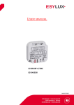
USER MANUAL CU-DIN DIM 6-CH 0…10V KNX EC10430329 MA00651401 USER MANUAL Table of contents 1 Description ............................................................................................... 3 2 Safety Instructions .................................................................................... 3 3 Product Function....................................................................................... 3 4 Hardware.................................................................................................. 4 4.1 4.2 Technical data ................................................................................ 4 Dimming mode ............................................................................... 6 4.2.1 Dimensional drawings .......................................................... 6 4.3 Wiring Diagram ............................................................................... 7 4.4 Maintenance and warnings ................................................................... 8 5 Software ................................................................................................... 8 5.1 5.2 5.3 5.4 5.5 5.6 6. Communication objects description ............................................................28 6.1 6.2 6.3 6. 4 6.5 4.6 6.7 6.8 6.9 7. Overview of database functions ......................................................... 8 Object/Association/Group address definition ....................................... 9 "General" function parameter .......................................................... 10 Function parameter - Channel "N" ................................................... 13 A>dimming configuration ............................................................... 17 A: Function .................................................................................. 19 5.6.1 A: "Staircase light" function ............................................... 20 5.6.2 A: "Flashing" function......................................................... 22 5.6.3 A: "Scene" function ............................................................ 23 5.6.4 A: "Threshold" function ....................................................... 24 5.6.5 A: "Heating" function ......................................................... 26 "General" objects ........................................................................... 28 "Channel A output" objects ............................................................. 28 "Response" objects ........................................................................ 29 "Statistics ON time" objects ............................................................ 29 "Staircase light" objects ................................................................. 30 "Flashing" objects .......................................................................... 30 "Scene" objects ............................................................................. 30 "Threshold" objects ........................................................................ 31 "Heating" objects ........................................................................... 31 Application ..............................................................................................33 7.1 Program functions diagram ............................................................. 33 8 Product disposal ......................................................................................34 9 ESYLUX Manufacturer´s guarantee .............................................................34 CU-DIN DIM 6-CH 0…10V KNX 2 / 34 USER MANUAL 1 Description The ESYLUX CU-DIN DIM 6-CH 0-10V KNX uses a KNX/EIB BUS to communicate with other KNX devices. The database must be downloaded to the dimmer actuator using ETS3.0E, ETS4 or ETS5, and this document describes how to use the product. Our products are manufactured according to EMC, electrical safety and environmental conditions. Dimmer actuators are used to control loads, such as: Lighting Curtains Heating Other equipment Note: Use this product only as intended (as described in the user instructions). Do not make any changes or alterations as this will render any warrantees null and void. You should check the device for damage immediately after unpacking it. If there is any damage, you should not install the device under any circumstances. If you suspect that safe operation of the device cannot be guaranteed, you should turn the device off immediately and make sure that it cannot be operated unintentionally. 2 Safety Instructions 3 Work on the 230 V power system must be carried out by authorized personnel only, with due regard to the applicable installation regulations. Switch off the power supply before installing the system. The 21 – 30 V KNX bus voltage cannot be used as 24 V operating or auxiliary voltage. Max. relay output: 10 A Product Function The dimmer actuator can dim 6 channels with independent AC loads. The control parameters are: Each channel has a maximum output current of 10A for dimmer actuators 1fold, and cannot exceed 10A in total. CU-DIN DIM 6-CH 0…10V KNX 3 / 34 USER MANUAL The following functions can be set individually for each output channel: Statistics total ON time Response status Recovery status Staircase light Flashing light Scene control Scene dimming Sequence control Threshold switch Heating actuator (PWM) 4 Hardware Technical properties of the ESYLUX KNX/EIB The technical data of the dimmer actuator is as follows. 4.1 Technical data Power supply Operating voltage (supply by the bus) Current consumption EIB/KNX (operating) Current consumption EIB/KNX (standby) Power consumption EIB/KNX (operating) Power consumption EIB/KNX (standby) 21-30 V < 15 mA < 5 mA < 450 mW < 150 mW Output nominal values Number of contacts Rated current Power loss per device at max. load Rated voltage 6 10 A 2.7 W 230V~ Output life expectancy Mechanical Life Electrical Life 50 years 20 years CU-DIN DIM 6-CH 0…10V KNX 4 / 34 USER MANUAL Dimmer actuator output without additional DC power Connections EIB / KNX Load circuits Cable shoe Tightening torque Bus Connection Terminal 0.8 mm Ø, single core Screw terminal with slotted head 0.2-4 mm² multi- core 0.4-6 mm² single core 12 mm Max. 0.4 Nm Operation and display Red LED and EIB/KNX program button for assigning the physical address. Factory settings are 15.15.255 Temperature range Operation Storage Transport Environment conditions Humidity 0 °C ~ + 45 °C – 25 °C ~ + 55 °C – 25 °C ~ + 70 °C max. 95 % Non-condensing Appearance design DIN-Rail Modular installation Modular Dimensions (H x W x 90 x 144 x 65 D) 0.49 Weight (unit kg) Use 35 mm mounting rail Installation Electric dimmer box Mounting position Material and colour CE Mark in accordance with EMC Standard LVD Standard RoHS CU-DIN DIM 6-CH 0…10V KNX Plastic, White 2004/1008/EC 2006/95/EC 2011/65/EU 5 / 34 USER MANUAL Note: All loads, at 230 V ~ Programming requires the EIB Software Tools ETS3.0E, ETS4 or ETS5. 130 Max. number of communication objects 254 Max. number of group addresses 254 Max. number of associations 4.2 Dimming mode 4.2.1 Dimensional drawings CU-DIN DIM 6-CH 0…10V KNX 6 / 34 USER MANUAL 4.3 Wiring Diagram Note: On the input side, the device is to be protected against short circuits with a 10 A circuit breaker. 1. Label area 2. Power input for load connection sequence 3. KNX/EIB connector 4. Programming button&programming LED 5. Contact position indication and manual operation 6. LED state 7. 24V input Note: a) Dimensions of the space to be provided for each dimmer. b) Dimensions and position of the means for supporting and fixing the dimmer within this space. c) Minimum clearance between the various parts of the dimmer and the surrounding parts where fitted. d) Minimum dimensions of ventilation opening, if needed, and their correct arrangement. CU-DIN DIM 6-CH 0…10V KNX 7 / 34 USER MANUAL e) Protective devices (e.g. fuses, automatic protective devices, etc.) to be connected to the load to avoid overloading. 4.4 Maintenance and warnings 5 Please read this user manual carefully before any operation. Do not operate close to interfering devices. The site should be well ventilated with a good cooling environment. Pay attention to damp proofing, quakeproofing and dustproofing. Avoid contact with rain, other liquids or caustic gas. Please contact professional maintenance staff or the ESYLUX service centre for repairs. Remove dust regularly and do not wipe the unit with volatile liquids such as alcohol, petrol, etc. In case of contact with damp or liquid, turn off immediately. Check the circuitry and other related circuits or cables regularly, and replace inadequate circuitry promptly. For security, each circuit must be protected by an MCB or fuse The installation location should be well-ventilated, with no moisture, movement or dust. Software The ESYLUX 0-10V Dimmer Actuator hast to be used with ETS3E to perform the configuration. The device type is CU-DIN DIM 6-CH 0-10V KNX and the database name is "ec10430329_ CU-DIN DIM 6-CH 0-10V KNX.VD4". All interfaces and functions use specific parameters. Please see the overview below. Each output channel of the dimmer actuators is independent and the same. It is therefore sufficient to understand how one operates. The following paragraph describes the first output channel in detail. 5.1 Overview of database functions The following table provides an overview of the functions and certain parameters of the switch actuator: General Cycle telegram (heartbeat) System delay after recovery x x x Statistics total ON time Voltage Recovery state x x Sequence Channel CU-DIN DIM 6-CH 0…10V KNX 8 / 34 USER MANUAL Dimming x x x Switch ON/OFF Relative dimming Absolute dimming Function Staircase light Flashing Scene Scene No.1-64 x x x Threshold Lower threshold Middle threshold Upper threshold Heating actuator x x x PWM Table 1: Database application overview. x 5.2 Object/Association/Group address definition The following table shows the max. number of communication objects, associations and group addresses. The object is assigned to certain functions of the channel output pages. If the functions are activated, the corresponding object will be available. One or more group addresses can be assigned to an object. The association will connect group addresses to the object. Type VD4 Max. number of communication objects Max. number of associations Max. number of group addresses ec10430329 130 254 254 Table 2: Overview the max. number of objects, max. number of associations and max. number of group addresses. Note: At least ETS 3.0 E is required for use. CU-DIN DIM 6-CH 0…10V KNX 9 / 34 USER MANUAL 5.3 "General" function parameter Fig 1: "General" parameter window “7 parameters can be set in the General window "System delay operation after recovery", "Cycle send general telegram" and "Enable sequence 1-5". System delay operation after recovery (2-255 s) The device will be delayed for 2-255 s after powering on. The default value is 2 seconds. The min. value is 2 seconds and the max. value is 255 seconds. Options: 2-255 s Power on, then start the timer, after setting the time, the dimming is operational. This function is selected by the user. Cycle send general telegram (1-65535 s, 0 - invalid) The range of the parameter is 0 to 65535 s. Zero disables the function, other values enable the function Options: 0-65535 s If the parameter is set to non-zero, the device will send telegram data cyclically when it times out. It sends the value alternately between 0 and 1. CU-DIN DIM 6-CH 0…10V KNX 10 / 34 USER MANUAL Enable sequence 1 Enable/disable the sequence. Options: Disable Enable Disable: Disables the sequence function Enable: Enables the sequence function. Set as follows Fig:1.1: "G: sequence 1" parameter window It includes 24 steps. Operating mode of sequence 1 Set the operating mode. Options: "1" to start, "0" to stop "0" to start, "1" to stop "1/0" to start, cannot stop 1" to start, "0" to stop: When "1" is received, sequence 1 runs. When "0" is received, sequence 1 stops. "0" to start, "1" to stop: When "0" is received, sequence 1 runs. When "1" is received, sequence 1 stops. "1/0" to start, cannot stop: When "1" or "0" is received, sequence 1 runs. Control mode of sequence 1 Set the control mode. Options: FWD CU-DIN DIM 6-CH 0…10V KNX 11 / 34 USER MANUAL REW Random FWD: Forward mode REW: Back/Rewind mode RANDOM: Random mode Running mode of sequence 1 Set the running mode Options: Single Cycle Single: Run only once. Cycle: Cycle run. Running time (0-255 hours,0 hours & 0 mins - unlimited) Set the sequence running time. Options: 0-255 Running time (0-59 mins, 0 hours & 0 mins - unlimited) Set the sequence running time. The longest time is 59 mins. Options: 0-59 Note: Unlimited when time set to 0 hours & 0 mins. Position after time-out If the sequence is running in Cycle mode and the run time is greater than zero, the sequence will return to the set position after timing out. Total 24 steps, configuration as follows: Step 1 configuration Options: invalid Scene No. 01 … Scene No. 64 Time for step 1 (0-65535 s) Set the time for the step. The longest time is 65535 s. Time for step 1 (0-999 ms) Set the time for the step. The longest time is 999 ms. Setting other steps is the same as for step 1. CU-DIN DIM 6-CH 0…10V KNX 12 / 34 USER MANUAL 5.4 Function parameter - Channel "N" Fig 2: "Channel A" parameter windows. In the "Channel A" parameter windows, you can set some common functions. Select the function and download the database to the device; the device will work in accordance with the selected function. Channel response state (1 bit) Options: Invalid 1 bit always response 1 bit only changed Invalid: There is no response. 1 bit always response: It always responds If the channel is ON, the response is 1 If the dimmer is OFF, the response is 0 1 bit only changed: It will respond when the dimmer state is changed Channel response state (1 byte) Options: Invalid 1 byte always response 1 byte only changed Invalid: there is no response. 1 byte always response: It always responds with the light level value. CU-DIN DIM 6-CH 0…10V KNX 13 / 34 USER MANUAL 1 byte only changed: It will respond when the light value is changed. Statistics total ON time to be allowed (0-65535 h = 7.4 years) Fig. 2.1: "Statistics total ON time to be allowed" This function is used to calculate the total ON time for the output channel. The maximum time is 65535 h. This function is very useful as you can find out the channel work status using this function. Options: Disable Enable Disable: No statistic time. Enable: Statistics time. Alarm when times out (1-65535 h, 0 - invalid) When the device's operating time reaches the set value the alarm will be triggered. The value range is 1-65535 h, 0 is invalid. Transmit telegram interval when alarm is triggered Set the alarm time interval. CU-DIN DIM 6-CH 0…10V KNX 14 / 34 USER MANUAL Status after bus voltage recovery Fig. 2.2: "Status after bus voltage recovery". Set the status of restore mode after power on for each channel. Options: Off Defined brightness value Last brightness value Off: After power on the channel's status is off. Defined brightness value: After power on the channel's status is the defined brightness value. The range is 0% to 100%. Last brightness value: After power on the channel's status is the last brightness value Maximum level Set the maximum level. Options: 0%(0)-100%(255) Upper threshold level Set the upper threshold level. Options: 0%(0)-100%(255) Lower threshold level Set the lower threshold level. Options: 0%(0)-100%(255) CU-DIN DIM 6-CH 0…10V KNX 15 / 34 USER MANUAL Minimum dimming level Set the minimum dimming level. Options: 0%(0)-100%(255) Fig. 2.3: Switch ON/OFF or Absolute dimming Fig. 2.4: Relative dimming Show the function page Set enable/disable and show the function page. Options: Disable Enable Disable: Don't show the dimmer function page. Enable: Show the function page for setting the dimmer function. CU-DIN DIM 6-CH 0…10V KNX 16 / 34 USER MANUAL 5.5 A>dimming configuration Fig. 3: A>dimming configuration. Switching ON fade time (0-255 s) Set the time for switching ON. Note: brightness 0%-100%/0-255 s Switching OFF fade time (0-255 s) Set the time for switching OFF. Note: brightness0%...100%/0..255 s Enable relative dimming Options: Disable Enable Disable: Doesn't allow relative dimming Enable: Allow relative dimming Note: Relative dimming fade time (brightness 0%-100%/0-255 s), the data length is 4 bits. CU-DIN DIM 6-CH 0…10V KNX 17 / 34 USER MANUAL Relative dimming is saved as the brightness of the switch Options: NO YES NO: the brightness value is not saved. YES: the brightness value is saved. Enable absolute dimming Options: Disable Enable Disable: Don't allow absolute dimming Enable: Allow absolute dimming Note: Absolute dimming fade time (brightness 0%-100%/0-255 s), the data length is 1 byte Absolute dimming is saved as the brightness of the switch Options: NO YES NO: the brightness value is not saved. YES: the brightness value is saved. CU-DIN DIM 6-CH 0…10V KNX 18 / 34 USER MANUAL 5.6 A: Function Fig. 4: Function window. The window for enabling/disabling the functions below. Enable "staircase light" function Enable "flashing" function Enable "scene" function Enable "threshold" function Enable "heating" function CU-DIN DIM 6-CH 0…10V KNX 19 / 34 USER MANUAL 5.6.1 A: "Staircase light" function Fig. 4.1: "Staircase light" window. For staircase applications Staircase lighting operation Options: "1" to start, "0" to stop "1" to start, "0" invalid "1/0" to start, cannot stop "1" to start, "0" to stop: When “1” is received the staircase light starts running automatically, stop with time-out or stop with “0”. "1" to start, "0" invalid: When “1” is received the staircase light starts running automatically, 0 is invalid. "1/0" to start, cannot stop: When data “1” or “0” is received the staircase light starts running automatically, cannot stop. Brightness value Set the brightness value of the staircase light. Brighter fade time: (0-255 s) Fade time from dark to bright in seconds. CU-DIN DIM 6-CH 0…10V KNX 20 / 34 USER MANUAL Darker fade time: (0-255 s) Fade time from bright to dark in seconds. Brightness duration: (0-255 mins) Duration in the bright state in minutes. Duration for brightness: (0-59 s) Duration in the brightness state in seconds. Change staircase lighting time via bus Options: Disable Enable Disable: Cannot modify staircase lighting delay off time via the bus, can only be set via the database. Enable: Allow user to modify staircase lighting delay off time via the bus. Warning staircase lighting Options: Disable Enable Disable: Disable alarm. Enable: Allow sending out warning state using warning data point for staircase light ON/OFF. CU-DIN DIM 6-CH 0…10V KNX 21 / 34 USER MANUAL 5.6.2 A: "Flashing" function Fig. 4.2: "Flashing" window. Flashing between ON and OFF in this mode. Flashing operation Three control modes for this function. Options: "1" to start, "0" to stop "1" to start, "0" invalid "1/0" to start, cannot stop "1" to start, "0" to stop: Start flashing with 1 and stop flashing with 0. "1" to start, "0" invalid: Start flashing with 1 and invalid with 0. "1/0" to start, cannot stop: Start flashing with 1 or 0, cannot stop. Brightness value Set the brightness value flashing mode. Brighter fade time: (0-255 s) Fade time from dark to bright in seconds. Darker fade time: (0-255 s) Fade time from bright to dark in seconds. Brightness duration: (0-255 mins) Duration in the bright state in minutes. CU-DIN DIM 6-CH 0…10V KNX 22 / 34 USER MANUAL Duration for brightness: (0-59 s) Duration in the bright state in seconds. Darkness duration: (0-255 mins) Duration in the dark state in minutes. Duration for darkness: (0-59 s) Duration in the darkness state in seconds. Flashing number (0-255, 0 - Unlimited) Flashing, range between 0 and 255. 0 is unlimited. Brightness once flashing number achieved Brightness once flashing stopped by overflow counter, the range is 0% (0)-100% (255) or invalid. 5.6.3 A: "Scene" function Fig. 4.3: "Scene" window. Scene dimming fade time: (0-255 s) Fade time in the scene mode in seconds. CU-DIN DIM 6-CH 0…10V KNX 23 / 34 USER MANUAL Total 10 scenes, configuration as follows, with the setting as per below. Each scene is the same as the following: Output assigned to (scene 1-64) Allocate the scene. Output brightness value Set the output brightness value 0%-100% Brighter/darker fade time (0-255 s) Set the brighter or darker time. 5.6.4 A: "Threshold" function Fig. 4.4: "Threshold" window. Brightness value for switching threshold ON Configure the brightness for switching ON Fade time for switching threshold ON (0-255 s) Configure the time for switching ON in seconds Fade time for switching threshold OFF (0-255 s) Configure the time for switching OFF in seconds CU-DIN DIM 6-CH 0…10V KNX 24 / 34 USER MANUAL Threshold 1 value is (0-255) Set threshold 1 value between 0 and 255. Default is 80. Threshold 2 value is (0-255) Set threshold 2 value between 0 and 255. Default is 180. Input value < Lower threshold If the value of the telegram received from the bus is lower than the minimum threshold value, the switch will function according to the option below (ON or OFF or Unchanged) Options: Unchange ON OFF Unchange: The channel switch position is set to unchange. ON: The channel switch position is set to ON. OFF: The channel switch position is set to OFF Lower threshold <= Input value <= Upper threshold If the value of the telegram received from the bus is between the lower threshold and the upper threshold, the switch will function according to the option below (ON or OFF or no action) Options: Unchange ON OFF Unchange: The channel switch position is set to unchange. ON: The channel switch position is set to ON. OFF: The channel switch position is set to OFF Input value > Upper threshold If the value of the telegram received from the bus is more than the upper threshold value, the switch will function according to the option below (ON or OFF or no action). Options: Unchange ON OFF Unchange: The channel switch position is set to unchange. ON: The channel switch position is set to ON. OFF: The channel switch position is set to OFF Change threshold 1 via the bus Options: Disable Enable Disable: Do not allow changing the threshold 1 value from the bus. Enable: Allow changing the threshold 1 value from the bus. CU-DIN DIM 6-CH 0…10V KNX 25 / 34 USER MANUAL Change threshold 2 via the bus Options: Disable Enable Disable: Do not allow changing the threshold 2 value from the bus. Enable: Allow changing the threshold 2 value from the bus. 5.6.5 A: "Heating" function Fig. 4.5: "Heating" window. Brightness value for switching heating ON Configure the brightness for switching ON Fade time for switching heating ON (0-255 s) Configure the time for switching ON in seconds Fade time for switching heating OFF (0-255 s) Configure the time for switching OFF in seconds PWM cycle time set (1-65535 mins) Options: 1-65535 mins The minimum cycle time is 1 minute CU-DIN DIM 6-CH 0…10V KNX 26 / 34 USER MANUAL PWM cycle time set (1-59 s) Options: 1-59 s The cycle time is set in seconds Control telegram Type of control can be 1 bit or 1 byte. Options: 1 bit PWM (ON-start/OFF-stop) 1 byte (255 - ON,0 - OFF, other value) 1 bit PWM (ON - start/OFF - stop): The PWM starts and switches ON when telegram value "1" is received, and stops when "0" is received. 1 byte (255 - ON/0 - OFF/other value): Switching ON when telegram value "255" is received, and switching OFF when "0" is received. The PWM runs and the PWM pulse width is set according to the telegram value received (1 to 254) The scale of ON This parameter sets the value of the PWM (pulse width). Options: 0% (OFF) 10% (26) 20% (51) 30% (77) 40% (102) 50% (128) 60% (153) 70% (179) 80% (204) 90% (230) 100% (ON) Running automatically after bus voltage recovery The PWM runs automatically when set to YES, the PWM runs manually when set to NO. Options: NO YES YES: PWM runs automatically at power on. NO: PWM runs manually. CU-DIN DIM 6-CH 0…10V KNX 27 / 34 USER MANUAL 6. Communication objects description Note: Take channel A as an example, other channels refer to channel A. 6.1 "General" objects NO 0 Object name General Function Send cycles Flags CRT Data type DPT 1.003 1 bit This communication object is always active and valid. Invert the telegram value sent to the bus in the next frame. E.g. the last telegram value is "1", the next telegram value is "0" General Sequence 1-5 CWU DPT 1.010 1-5 1 bit These communication objects are used to start or stop a sequence. Send telegram value "1" to start a sequence. Send telegram value "0" to stop a sequence. 6.2 "Channel A output" objects NO 10 Object name Output A Function Output channel CU-DIN DIM 6-CH 0…10V KNX Flags CWU Data type DPT 1.001 1 bit 28 / 34 USER MANUAL This communication object of the output channel is used for switching ON/OFF, the dimmer output channel is ON when the object receives the value "1". The dimmer output channel is OFF when the object receives the value "0" Output A Relative dimming C W U DPT 3.007 11 (4 bit) 4 bit This communication object of the output channel is used for relative dimming. Relative dimming mode is UP or DOWN. Dimming UP when the received telegram value is increased, and dimming DOWN when the received telegram value is decreased. Output A Absolute dimming C W U DPT 5.001 12 (8 bit) 1 byte This communication object of the output channel is used for absolute dimming. The output channel absolute dimming to a brightness according to a received telegram value. 6.3 "Response" objects NO 13 Object name Output A Function Flags Data type Response status CRT DPT 1.001 (1 bit ) 1 bit This communication object is used for the output channel A response state. If the channel state is ON the response state is "1", otherwise the state is "0". Output A Response status CWU DPT 5.001 14 (1 byte) 1 byte This communication object is used for the output channel A brightness response. 6. 4 "Statistics ON time" objects NO 15 Object name Output A Function Flags Data type R/W total ON CRWTU DPT 7.007 time 2 byte This communication object is used for changing the initial value. Statistical ON time increases again every hour. Output A Alarm when CRT DPT 1.005 16 total ON times 1 bit out This communication object is used for the alarm when the statistical ON time reaches a set maximum value. CU-DIN DIM 6-CH 0…10V KNX 29 / 34 USER MANUAL 6.5 "Staircase light" objects NO 19 Object name Output A Function Staircase light Flags CWU Data type DPT 1.001 1 bit This communication object is used for starting or stopping the staircase light. The staircase light starts when the telegram value "1" is received. Output A Change staircase C W U DPT 7.005 20 light time 2 byte This communication object is used for changing the staircase light time. Output A Staircase light CRT DPT 1.005 21 warning 1 bit This communication object is used for the staircase light warning. 4.6 "Flashing" objects NO 22 Object name Output A Function Flashing Flags CWU Data type DPT 1.001 1 bit This communication object is used for flashing the channel light. The channel light flashes when the start value is received. 6.7 "Scene" objects NO. 23 Object name Output A Function Scene (8 bit) Flags CWU Data type DPT 18.001 1 byte This communication object is used for calling or saving the output channel scene See the following explanation for scene control: C Telegram value: R N N N N N N C: 0 - Call scene 1 - Store scene (If scene allocated and the scene is in the current switch state) R: Reserved CU-DIN DIM 6-CH 0…10V KNX 30 / 34 USER MANUAL N: Scene no. (bin: 000000-111111 = no.1-64) Example: Hexadecimal 00h------call scene 1 (if scene allocated) 01h------call scene 2 (if scene allocated) 3Fh------call scene 64 (if scene allocated) 80h------store scene 1 (if scene allocated) 81h------store scene 2 (if scene allocated) BFh------store scene 64 (if scene allocated) 24 Output N Scene dimming C W U DPT 3.007 (4 bit) 4 bit This communication object is used for dimming the output channel scene 6.8 "Threshold" objects NO 25 Object name Output A Function Threshold input Flags CWU Data type DPT 5.004 1 byte If this communication object is active, the input value of the telegram received from the bus is compared with threshold 1 and threshold 2 to calculate the switch state according to the database setting. Output A Change CWU DPT 5.004 26 threshold 1 1 byte Change threshold 1 value via the bus. Output A Change CWU DPT 5.004 27 threshold 2 1 byte Change threshold 2 value via the bus. 6.9 "Heating" objects NO 28 Object name Output A Function Flags Data type Heat with 1 bit CWU DPT1.001 control 1 bit If heating actuator is selected, this communication object is displayed and is valid by default. PWM starts when telegram "1" is received, PWM stops when telegram "0" is received, it starts running automatically when power on is set by ETS. Output A Heat with 1 byte C W U DPT 5.004 28 control 1 byte CU-DIN DIM 6-CH 0…10V KNX 31 / 34 USER MANUAL If "heat with byte control" is selected, this communication object has been displayed and is valid. Can modify value of PWM by receiving 1 byte data. Output is always ON if received value is 255, output OFF if received value is 0, otherwise PWM output is according to the value of the telegram received from the bus.6 DPT 1.001 Output A Forced position CWU 29 1 bit CU-DIN DIM 6-CH 0…10V KNX 32 / 34 USER MANUAL 7. Application 7.1 Program functions diagram Program start General Channel function Disable Sequence Disable Enable Enable Scene Disable Enable Staircase light Disable Enable Flashing Disable Enable Threshold Disable Enable Heating Disable Enable OUTPUT CU-DIN DIM 6-CH 0…10V KNX 33 / 34 USER MANUAL 8 Product disposal This device must not be disposed of as unsorted household waste. Used devices must be disposed of correctly. Contact your local town council for more information. 9 ESYLUX Manufacturer´s guarantee ESYLUX products are tested in accordance with applicable regulations and manufactured with the utmost care. The guarantor, ESYLUX Deutschland GmbH, Postfach 1840, D-22908 Ahrensburg, Germany (for Germany) or the relevant ESYLUX distributor in your country (visit www.esylux.com for a complete overview) provides a guarantee against manufacturing/material defects in ESYLUX devices for a period of three years from the date of manufacture. This guarantee is independent of your legal rights with respect to the seller of the device. The guarantee does not apply to natural wear and tear, changes/interference caused by environmental factors or damage in transit, nor to damage caused as a result of failure to follow the user or maintenance instructions and/or as a result of improper installation. Any illuminants or batteries supplied with the device are not covered by the guarantee. The guarantee can only be honoured if the device is sent back with the invoice/receipt, unchanged, packed and with sufficient postage to the guarantor, along with a brief description of the fault, as soon as a defect has been identified. If the guarantee claim proves justified, the guarantor will, within a reasonable period, either repair the device or replace it. The guarantee does not cover further claims; in particular, the guarantor will not be liable for damages resulting from the device’s defectiveness. If the claim is unfounded (e.g. because the guarantee has expired or the fault is not covered by the guarantee), then the guarantor may attempt to repair the device for you for a fee, keeping costs to a minimum. CU-DIN DIM 6-CH 0…10V KNX 34 / 34