1
V8600A
RC Systems
voice synthesizer
now you’re talking!
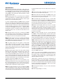
ELECTRICAL SPECIFICATIONS
ABSOLUTE MAXIMUM RATINGS*
Supply voltage, VCC . . . . . . . . . . . . . . . . . . . . . . . – 0.3 V to + 6.5 V
DC input voltage, VI . . . . . . . . . . . . . . . . . . . – 0.3 V to VCC + 0.3 V
Operating temperature, TA. . . . . . . . . . . . . . . . . . . . 0 °C to + 70 °C
Storage temperature, TS . . . . . . . . . . . . . . . . . . – 55 °C to + 125 °C
* WARNING: Stresses greater than those listed under “Absolute
Maximum Ratings” may cause permanent damage to the device.
This is a stress rating only; operation of the device at any condition
above those indicated in the operational sections of these specifications is not implied. Exposure to absolute maximum rating conditions for extended periods may affect device reliability.
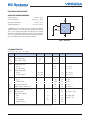
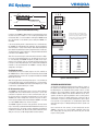
Figure 1. Test Circuit
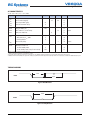
DC CHARACTERISTICS
TA = 0 °C to + 70 °C, VCC = + 5 V ± 10%
Symbol
Parameter
Min
Typ
Max
Unit
Test Conditions
VIL
Input voltage, Low
– 0.3
0.8
V
VIH
Input voltage, High
2.8
VCC + 0.3
V
VHYR
Input hysterisis, RES#
0.2
1.8
V
VOL
Output voltage, Low
0.3
0.5
V
V
IOL = 6 mA
IOL = 2 mA
VOH
D0 – D7
All other outputs
Output voltage, High
D0 – D7
VCC – 0.5
V
IOH = – 6 mA
All other outputs
VCC – 0.5
V
IOH = – 2 mA
– 10
– 120
10
µA
µA
µA
VI = 0 V
VI = 0 V
VI = VCC
± 5
µA
VI = 0 to VCC
IIL
Input load current, Low
IIH
D0 – D7
All other inputs
Input load current, High
IOZ
Output leakage current, D0 – D7
RL
Output load impedance, SP+, SP–
POUT
ICC
SP output power
Supply current (Note 1)
Active
Idle
Sleep/Standby
W
8
W
RL = 8 W f = 1 kHz
35
3
20
mA
mA
µA
All outputs open;
all inputs = VCC
40
mA
1
11
1
0.8
Program (Note 2)
1 Add 5 mA (typ) if RS-232 transceiver option is installed.
2 Applies during internal programming operations: greeting message, dictionary, sound library and microcode updates.
4