1
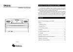
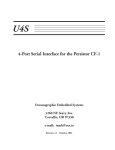
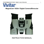
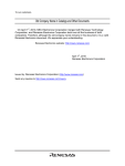
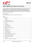
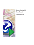
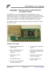
USB-1
USB-Compatible Interface for the Persistor CF-1
Oceanographic Embedded Systems
1260 NE Seavy Ave.
Corvallis, OR 97330
e-mail: [email protected]
Revision 1.0 November, 2001
Introduction
The USB-1is a peripheral interface for the Persistor CF-1 that implements a fast USB serial
link to a host computer. The interface has an onboard regulator to provide +5V from the
battery input pin of the CF-1 and does not draw any power from the USB host. The USB-1 is
compatible with the Sandwich Card specification from Persistor Instruments but does not
have an onboard PIC processor for card identification and can be set for only a subset of 8 of
the possible 32 addresses in the full Sandwich Card specification.
Setup and Testing
Setting up the USB-1 is as simple as plugging the CF-1 into the USB-1, connecting power,
serial I/O and the USB cable to your PC , then running the USBLink programs. Generally,
you will plug the USB-1 into a motherboard of some kind, which will provide power to the
USB-1 and CF-1.
Serial Port Connections
The serial I/O connector provides the same RS-232 signals implemented on the Recipe cards
from Persistor. The header is compatible with the IDC-10 to DB9F connector also provided
by Persistor. The pin connections of this cable are shown in figure 1. You must connect this
cable and us MotoCross on the PC to download programs and communicate with the CF-1.
DB9F Cable
5
9
4
8
3
7
2
6
1
GND
RI
DTR
CTS
TXD
RTS
RXD
DSR
DCD
9
7
8
5
6
3
4
1
2
Figure 1. CF-1 Serial I/O
USB Connectors
The USB-1 can connect to your PC either through the USB mini-B connector and cable or
with a custom cable connected to the 4-pin Molex connector. The pin definitions for the
Molex connector are shown in figure 2. Note that the pin usage is different from the USB
Mini-B connector.
USB-1 User’s Manual Release 1.0
Page 1
1
2
3
4
USB +5
USBDP
USBDM
GND
4 3 2 1
Figure 2. Molex Connector Pin Usage
Power Supply Input
The USB-1 uses +3.3V power from Pin 11 (VLIN) of Connector C on the CF-1. It will also
provide a regulated +5V to the USB circuitry from the battery input on pin 13 of Connector
C. Because the USB circuitry requires at least 4.75V input, you should ensure that the
battery input voltage at pin 13 is at least 5.0 Volts. The USB-1 also provides jumper pads
that will allow you to provide its regulated 5V to pin 5 of the CF-1 connector for use with an
AD16S or similar card that requires +5V on that pin. (Revision 1.1 PC Boards only)
The +5V supply to the USB interface can be switched off using a function in the USB-1
library. An output bit of an internal register is used to control the Shutdown input of the
LTC1521 regulator. The register and regulator will automatically shut down the +5V supply
when the CF-1 is in the low-power Suspend mode. If you use this capability, you should
remember that turning on the +5V will also activate the USB circuit. However, if there is no
cable connected to the USB input, the USB circuitry on the interface will automatically drop
into a low power suspend mode.
USB-1 Software
The diskette provided with the USB-1 includes both the source code and executable .RUN
file for USBLink for the CF-1. This program, when run with the USBLINK.EXE program
for the PC, allows you to transfer files from the CF-1 to the PC at up to 200kBytes per
second. You may also download this software, as well as the C++ Builder source for the
USBLINK.EXE program, from the OES web page (www.oes.to)
Your first step should be to assemble your CF-1, the USB-1 and an appropriate motherboard.
Next, load the USBLink.run program onto your CF-1 with MotoCross. At this point you can
plug in the cable between the USB-1 and your PC’s USB input port. When you execute the
USBLink program, it will automatically activate the USB interface. Your PC should sense
that a new USB device has been connected and attempt to load drivers for the new hardware.
The FTDI drivers on the USB-1 diskette are used with the interface. When you load the
drivers, Windows should notify you that a new device has been added: the ‘OES USB
Interface for the CF-1’. At this point, you are ready to use the USBLink PC program as
described later in this manual.
USB-1 User’s Manual Release 1.0
Page 2
Hardware
The USB-1 is assembled on two-sided printed circuit board using both surface-mount and
through-hole components. The arrangement on the components on the board is shown in
figure 3.
USB Connectors
USB Interface
IC
Address Decoding
Figure 3. Component Arrangement on USB-1
USB Interface
The USB-1 uses the FT8U245AM USB interface circuit from FTDI Incorporated. This IC,
and its accompanying components, form a complete USB interface that handles all the
complexities of the USB serial transfer protocol. To the CF-1, the USB interface appears as a
data register and a status/control register. USB data from the host appears in the read register,
when the status register indicates that data is available. The ‘245 has an internal FIFO that
buffers the incoming data. Data to be transferred to the host is written to the write register
when the status register indicates that space is available in the internal FIFO of the ‘245. A
complex programmable logic device controls the interface between the CF-1 3.3V address
and data bus and the 5V FT8U245AM. This IC provides I/O signals that are compatible with
the 5V TTL levels of the ‘245 while operating from the 3.3V linear supply of the Persistor
CF-1. The outputs of the CPLD are switched into a high-impedance mode when the +5V
supply power to the USB interface is shut down.
Sandwich Card Address Selection
Persistor Instruments has selected the address ranges from FFFFF8000 to FFFFBFFF and
FFFF0000 to FFF3FFF for Sandwich Cards. The first address range is decoded using CS8
and the logic on the card. The second range is decoded using CS10. Each of these ranges is
divided into 16 blocks 1024 bytes in length for each Sandwich Card. The details of the
addressing are covered in the “Sandwich Card Chip Select Reference” from Persistor.
USB-1 User’s Manual Release 1.0
Page 3
The USB-1 uses CS8 and the CF-1 address bus bits to select one of the second eight memory
slots in the Sandwich Card addressing range. Although the address decoding logic will
respond to several addresses in the selected 1KByte range, the USB-1 actually uses only a
single 8-bit status register and a single 8-bit data register.
The memory slot used by the USB-1 is selected with the 2mm jumpers at JP1. The jumpers
set the three bits that determine a slot address from 8 to 15. The card is normally shipped
configured for slot 8. The setup of the jumpers is shown in Figure 4.
Figure 4. Address Selection Jumpers
Since the USB-1 does not have an onboard Sandwich Card Supervisor PIC controller, the
CF-1 BIOS firmware that communicates with standard Sandwich Cards will not detect the
USB-1. If you are using other Sandwich Cards in your system, you should make sure that
none of them use the same slot selected for the USB-1.
Serial I/O Connector
The serial port header has the same pinout as the header on the hasty-pudding recipe card. It
is compatible with the ribbon-cable and 9-pin connector provided with that interface.
Software
USBLink CF-1 Firmware
The diskette provided with USB-1 provides source and compiled .RUN code for the
USBLink firmware. This firmware provides a good example of the use of the USB-1.
USBLink.run must be loaded into the CF-1 using the MotoCross loader from Persistor.
USBLink PC Program
The USBLink program for the PC has a single window. You may wish to open the
application to view the window as you review these instructions. A screen image was not
included in this manual as it approximately doubles the size of the manual PDF file. The
left-hand panel of the window will show the directory of the CF-1 drive selected. The righthand panel shows the destination directory for the transferred files. In order to update the
directory and transfer files, the USBLink program must be running on the CF-1.
USB-1 User’s Manual Release 1.0
Page 4
Once the programs are running on the PC and CF-1, press the ‘Open USB’ button. This
will initialize the connection and the “No Connection” panel will change to “CF-1 USB
Interface”.
You may now get the directory information from the CF-1 by pressing the “Get Directory”
button. In a few seconds, the left-hand panel will show the CF-1 directory listing. Scroll
bars will be added to the right side of the panel if the directory listing is larger than the
panel.
You may change to a subdirectory on the CF-1 by selecting the subdirectory name and
pressing the “Change Directory” button. The directory display will be updated in a few
seconds as the information is transmitted from the CF-1. To step back one directory level or
to the main directory you can use the “.” and “..” entries.
Before you transfer files to the PC, you should select an appropriate subdirectory in the righthand panel. This panel provides a standard tree display of the directory structure of your PC.
The directory selected will be shown in text format below the tree diagram.
To transfer files to the PC, select one or more files in the left-hand panel. You may select
multiple non-contiguous file names with CTRL-Click or contiguous file names by dragging
the mouse over several names. The complete destination name of the first selected file will
appear below the PC tree diagram. The transferred files will have the same name on the PC
that they have on the CF-1.
WARNING! If a file already exists on the PC with the same name, it will be overwritten
without further notification!
Once you have made your selection, press the “Transferà” button. The files will be
transferred in sequence. The byte count indicator will show the length of the last file
transferred. If you have selected multiple files for transfer, they will be transferred in the
order in which they appear in the directory listing for the CF-1.
While the transfer is taking place, the serial port of the CF-1 will receive transfer status
information, including an estimated transfer rate. The transfer rate is calculated in an
approximate manner and will vary considerably depending on the length of the file
transferred. For large files, the transfer rate is generally about 198Kbytes per second. This
rate is limited by the speed with which the CF-1 can fetch data from a compact flash card or
hard disk drive.
USB-1 Library
A library of software routines for the USB-1 is provided in MetroWerks library format for the
MetroWerks CodeWarrior development system. The library files (USB1.lib and USB1.h)
provide routines to initialize the A/D interface, control the +5V power and transfer data to
and from the USB interface. The CF-1 USBLink application source code shows how the
library functions may be used to transfer data to and from the PC.
USB-1 User’s Manual Release 1.0
Page 5
Function Prototype
void USBSetup(short scbslot, ulong USBaddr);
Parameters
scbslot selects which of which scb slot number will be used with the USB interface.
USBaddr is the memory address corresponding to the scb slot. You will generally use the
SCBSetup BIOS function to find that address.
Usage
This function sets up the chip select for USB interface.
Function Prototype
void USBEnable(void);
Parameters
NONE
Usage
This function turns on power to the USB interface and sets internal logic bits to enable the
interface.
Function Prototype
void USBDisable(void);
Parameters
NONE
Usage
This function turns off power to the USB interface and sets internal logic bits to disable the
interface.
Function Prototype
char USBGetChar(void);
Parameters
NONE
Usage
This function returns the next available character from the USB interface. If no character is
waiting, the return value is undefined. You should always call USBWaiting() to determine
that a character is available before calling USBGetChar();
USB-1 User’s Manual Release 1.0
Page 6
Function Prototype
bool USBWaiting(void);
Parameters
NONE
Usage
This function returns true when an input character is available from the USB interface.
Since the USB interface IC contains a received character FIFO, there may actually be many
characters available.
Function Prototype
void USBPutChar(char ch);
Parameters
ch is the output character to be sent to the USB interface.
Usage
This function sends data to the PC via the USB interface. The interface contains a FIFO to
handle the transmitted characters, and the function checks to see if the FIFO has space
available before storing the character. If the FIFO is full, it may take several milliseconds to
send the character.
Function Prototype
void USBSendBlk(void * dp,
unsigned short count);
Parameters
dp is a void pointer to the block of data to be transmitted. count is the number of characters
to transmit.
Usage
This function transmits a block of data to the host pc. The function is written in highly
optimized assembly language to maximize the transmission rate.
Schematic Diagram
The schematic diagram of the USB is included on the USB disk as a separate PDF file. The
internal logic of the XR32064 CPLD is not shown as it is considered proprietary information.
USB-1 User’s Manual Release 1.0
Page 7