1
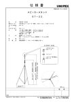
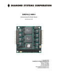
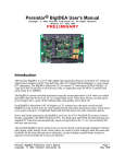
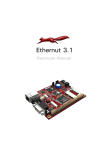
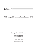
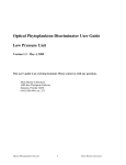
U4S
4-Port Serial Interface for the Persistor CF-1
Oceanographic Embedded Systems
1260 NE Seavy Ave.
Corvallis, OR 97330
e-mail: [email protected]
Revision 1.1 October, 2001
Introduction
The U4S is a peripheral interface for the Persistor CF-1 that provides four channels serial I/O
with user-selectable baud rates and either polled or interrupt-driven data transfer. The
interface card also provides solder pads for an optional RS-485 transceiver and a 10-pin
ribbon cable connector for CF-1 console serial I/O.
Setup and Testing
Setting up the U4S requires plugging the CF-1 into the U4S, then plugging the two cards
into a recipe card or motherboard to provide power, connecting the CF-1 serial I/O user
serial inputs, then running one of the test programs.
CF-1 Serial Port Connections
DB9F Cable
The console serial I/O
GND
connector provides the
5
9
RI
9
same RS-232 signals
DTR
4
7
8
CTS
implemented on the Recipe
8
TXD
3
5
6
cards from Persistor. It is
RTS
7
RXD
included since plugging
2
3
4
DSR
6
the U4S into a recipe card
DCD
1
1
2
blocks access to the serial
connector on the recipe
Figure 1. IDC10 to DB9F Cable
card. The header is
compatible with the IDC-10 to DB9F connector also provided by Persistor. The pin
connections of this cable are shown in figure 1.
Driver Expansion Connections
The U4S has a set of pads for an 8-pin surface-mount RS-485 transceiver. This driver can be
used in place of the RS-232 drivers for channel 4. If your application requires the use of an
RS-485 driver, please contact OES for further instructions in the use of this option
Power Supply Input
Power is provided to the U4S and the CF-1 through the battery input pin on the 50-pin
connector (Pin 13). The U4S uses VReg on Pin 9 to provide power to the UART and RS232 driver. Your motherboard or recipe card should either connect VREG (pin 13) to VLin
(pin 11) or provide a regulated 3.3Volts to pin 13.
When operating at full speed and writing to the compact flash disk, the CF-1 can draw up to
70mA. the U4S adds only about 20mA—depending on the loading of the RS232 ports
connected to the card. You should use a current-limited supply set to about 100mA when
developing and testing a new system.
U4S User’s Manual Release 1.1
Page 1
The CF-1 linear regulator can accept input voltages to 20Volts without damage. However, if
you have a power supply of greater than 11 Volts, it would probably be best to implement a
step-down switching converter to provide about 5 volts to the CF-1. A reasonably efficient
converter will reduce the current drain on the supply—which can greatly extend the life of a
battery. Please contact OES if you have a supply of greater than 12Volts where current drain
is important.
Test Software
The diskette provided with the U4S includes several compiled applications that you may use
to test your U4S and CF-1. You may also download this software, and other example
programs as they are developed, from the OES web page (www.oes.to)
Hardware
The U4S is assembled on two-sided printed circuit board using both surface-mount and
through-hole components. The arrangement on the components on the board is shown in
figure 2.
CF-1 Console Serial
Connector
ST16C654
UART
Serial Connector I/O
Connector
Figure 2. Component layout on U4S PC board.
Exar 16C654D Quad UART
The Exar 16C654 is a quad UART integrated circuit that is designed to interface both to
IBM PC and Motorola 68000 buses. The IC provides each channel with a separate baud rate
generator, control and configuration registers, and 64-byte First-In-First-Out (FIFO) buffers.
These FIFOs greatly reduce the number of interrupts that the processor must handle during
high-speed communications sessions.
The 16C654 is powered directly by the +3.3V supply from the CF-1. It normally requires
only about 3mA during operation. Since there is no way to shut off power to the UART
during operation, you cannot eliminate the power drain of the UART except by putting the
CF-1 into the suspend mode—which turns off the +3.3V supply. It is not possible to simply
turn off power to the 16C654, since it is directly connected to the address and data busses of
the CF-1’s microcontroller.
U4S User’s Manual Release 1.1
Page 2
U4S Serial I/O Connections
The U4S provides a 20-pin dual-row right angle header for Serial I/O. All the odd-numbered
pins are connected to system ground. The serial I/O signals appear on the even-numbered
pins as shown in Figure 3.
RX4
RX2
TX2
TX4
RX3
RX1
485A
485B
TX3
TX1
2
4
6
8
10
1
3
5
7
9
12 14
11
16
13 15
18
20
17 19
Ground
Figure 3. Serial I/O Connector Pin Assignment
Chip-Select Jumpers
74LVC138
The 16C654D UART is connected directly to the address and data busses of the CF-1. In
order for it to operate properly, the UART must respond to a unique set of memory addresses. The Sandwich Card specifications allocate a 32-KByte block of memory, divided
into 32 1-KByte blocks for all the Sandwich Cards in a system. Two sets of address jumpers are used to select one of
these blocks for a particular
card. The 1-KByte blocks are
CS1
Note: These two jumpers
generally referred to as address
+16
+0
must be moved as a pair
slots. The default slot for a
+0
+8
U4S is 5. The layout of the
CS2
address jumpers for slot 5 is
+0
+1
shown in Figure 4. These chip+2
select jumpers appear in the
+3
+4
upper left corner of the board
+5
in Figure 2. If a second U4S
+6
+7
card is added to your system,
you should set CS2 to select
block 6.
Figure 4. Layout of Chip -Select Jumpers
U4S User’s Manual Release 1.1
Page 3
Sandwich Card Supervisor and Environment Variables
The U4S has an onboard Sandwich Card Supervisor (SCS) chip which can inform the CF-1
of the type and serial number of the U4S card. This supervisor chip communicates with the
CF-1 using a serial protocol on two seldom-used pins, IRQ7 and MCLK. The firmware
library for the U4S will interrogate the SCS of any attached Sandwich Cards to be sure there
is a U4S available before it will attempt to transfer data to and from the UART chip. However, the SCS supervisor cannot easily determine the slot address of the card--which the
library routines need for proper operation. For this reason, you should define an environment variable to inform the software which slot is being used by the CF-1. You can do this
by typing the following line at the PicoDos prompt:
set SCB.5=U4S.3020.1000.100.2
This line defines an environment variable named SCB.5 and associates the data string
“U4S.3020.1000.100.2” with the name. The name and data are stored in the virtuall
EEPROM of the CF-1. The “SCB.5” indicates that the variable is associated with a sandwich card in slot 5. (Each SCB variable will have the slot number after the period in the
name.)
The data string defines the card as a U4S and indicates the manufacturers’ product identifier
(3020) and the serial number of the board (1000). It also indicates the minimum Chip Select
pulse width (100 nanoseconds) and the interrupt used by the board (2). Periods must be used
as separators because more common separators, such as commas or spaces, interfere with the
storage routines for environment variables.
The diskette included with the U4S includes a program, FINDU4S.RUN, which will search
the memory occupied by the sandwich card slots and attempt to find any U4S cards in the
system. If it finds a U4S, it will set the appropriate environment variable. This program
reads and writes a data pattern to all the potential memory addresses that might be used by
certain registers on the U4S. However, if it reads and writes to an address occupied by
another type of peripheral, it may have an adverse affect on that peripheral.
WARNING: The FINDU4S program may adversely affect other peripherals. You
should not run this program if other peripherals may be using CS8 or CS10.
Interrupt Selection
When used in interrupt-driven operation, the U4S can interrupt the processor using IRQ2 or
IRQ5 . The U4S is normally shipped with IRQ2 selected. If you are using IRQ2 for other
interrupts in your system, you may select IRQ5 by moving the jumper. The PIC Sandwich
Card Supervisor and U4S firmware will determine which interrupt is selected and set up the
software to use it properly.
U4S User’s Manual Release 1.1
Page 4
Stacking Multiple Sandwich Cards
The U4S, and other sandwich cards, are designed to be stacked to allow several cards to be
included in your system. The cards stack with 0.4 inches between adjacent board. (If you
don’t have 0.4” spacers, try a 3/8” spacer and a 0.032” washer.)
Software
U4S Library
A library of software routines for the U4S is provided as a binary library compatible with
the MetroWerks Codewarrior Pro development system.. The library files (U4S.lib and
U4S.h) provide routines to initialize the quad UART and to send and receive data from the
serial I/O ports. The serial ports may be operated in either polled mode or in interruptdriven mode with buffer sizes you select.
Library Functions
The following functions are defined in the U4S library. The header file and library are
included on the diskette.
Function Prototype
short U4SFindCards(bool verify);
Parameters
When Verify is true, function will poll the register addresses of potential U4S card slots to
verify the presence of the UART hardware.
Return Value
The function returns the number of U4S cards found.
Usage
This function searches the environment variables to see if they indicate a U4S at any valid
slot number. If the return value is zero, you have no U4S cards available and should not use
any further library functions. If a valid card is found, a record in the u4Devs array is filled
in, indicating the base address of the U4S slot and the IRQ used by the card.
Function Prototype
void U4SInitChannels(void);
Usage
This function initializes the registers of the U4S cards found in the call to U4SFindCards.
(In the first release, only the first card is initialized.)
U4S User’s Manual Release 1.1
Page 5
Function Prototype
bool U4SInitInputQueue(short chan, short qsize);
Parameters
chan selects which of the UART channels to initialize (1 through 4).
qsize sets the size of the queue to be used with the channel. Reasonable values should be in
the range from 128 to 4095. Memory for the data in the input queue is allocated in the
system heap with a call to malloc().
Return Value
The boolean result is true is the queue is successfully initialized. It is false if the memory for
the queue data could not be allocated.
Usage
This function is used to define queue sizes for an input channel and to set up the channel for
interrupt-driven I/O. If you do not call this function, the channel will operate in polled
mode. (In the initial release, queues are set up only for the first U4S card.)
Function Prototype
bool U4SInitOutputQueue(short chan, short qsize);
Parameters
chan selects which of the UART channels to initialize (1 through 4).
qsize sets the size of the queue to be used with the channel. Reasonable values should be in
the range from 128 to 4095. Memory for the data in the input queue is allocated in the
system heap with a call to malloc().
Return Value
The boolean result is true is the queue is successfully initialized. It is false if the memory for
the queue data could not be allocated.
Usage
This function is used to define queue sizes for an input channel and to set up the channel for
interrupt-driven I/O. If you do not call this function, the channel will operate in polled
mode. (In the initial release, queues are set up only for the first U4S card.)
U4S User’s Manual Release 1.1
Page 6
Function Prototype
bool U4SInitPPB(short chan, short qsize, vfptr notify);
Parameters
chan selects which of the UART channels to initialize (1 through 4).
qsize sets the size of the ping-pong buffer to be used with the channel. Reasonable values
should be in the range from 512 to 4095 bytes. Memory for the buffer is allocated in the
system heap with a call to malloc(). Ping-pong buffers are used for input only.
Return Value
The boolean result is true is the ping-pong buffer is successfully initialized. It is false if the
memory for the buffer could not be allocated.
Usage
This function is used to set up a ping-pong buffer for an input channel and to set up the
channel for interrupt-driven I/O. (In the initial release, a PPB can be set up only for the first
U4S card.) Ping-Pong buffers are an efficient way to collect data to be written to flash disk.
They are much less useful than queues when you need to examine the incoming serial data
stream.
Function Prototype
void U4SConfigure(short chan, long baud, char parity,char
bits, char stop);
Parameters
chan selects which of the UART channels to initialize (1 through 4).
baud sets the baud rate. You can select standard baud rates from 300 to 230,400 baud. Both
the input and output channels will use the selected baud rate.
parity defines the parity of the characters transmitted and received. Valid settings are :
‘n’
‘e’
‘o’
‘0’
‘1’
no parity bit used
set parity bit so an even number of logic 1s are tranmitted
set parity bit so an odd number of logic 1s are transmitted
set parity bit to 0
set parity bit to 1
bits sets the number of bits in the character. Only values of 5 through 8 are valid. Only
values of 7 and 8 are used in normal computer-to-computer applications.
stop sets the number of stop bits. Only values of 1 and 2 are valid.
U4S User’s Manual Release 1.1
Page 7
Usage
This function must be called before the channel is used, to properly define the baud rate and
character format.
Function Prototype
void
U4STxPutChar(short chan, ushort data);
Parameters
chan selects which of the UART channels that will transmit the data(1 through 4).
data specifies the character to send. The parameter is of type ushort because the standard
libraries use and INT or SHORT—but you will usually be transmitting characters.
Usage
This function is used to transmit data through the UART channel. In polled mode, it will
wait inside the routine until the UART transmit register is empty (up to one character time).
However, there will be no delay unless the FIFO buffer is full. In interrupt-driven mode, the
character will be put into the queue to be transmitted by the interrupt handler.
Function Prototype
ushort U4SRxGetChar(short chan);
Parameters
chan selects which of the UART channels will receive the data (1 through 4).
Return Value
The return value is the character received (promoted to a ushort).
Usage
In polled mode, the function will wait until a character is received. This could hang your
program! In interrupt-driven mode, the routine will return the character 0x00 if there is no
received data available. For this reason, you should always call U4RxCharsAvail() to check
for received data before you call U4RxGetChar().
Function Prototype
ushort U4SRxCharsAvail(short chan);
Parameters
chan selects which of the UART channels to check for incoming data(1 through 4).
U4S User’s Manual Release 1.1
Page 8
Return Value
The return value is the number of receive characters available.
Usage
In polled mode, the return value will be one when there is a received character available.
Since the 16C654 has a 64-byte receive FIFO, you may have to call U4RxCharsAvail() and
U4RxGetChar() many times to get all the characters received. In interrupt-driven mode, the
function returns the number of characters in the receive queue. There may be characters in
the UART FIFO which have not yet been added to the input queue.
Function Prototype
bool U4STxComplete(short chan);
Parameters
chan selects which of the UART channels to check for outgoing data transmission complete.
Return Value
The return value is true when all transmission from the channel is complete
Usage
This function can be used to determine whether all transmission from the serial channel is
complete. It checks both the transmitter holding register (and FIFOs if enabled) and the
serial data shift register.
Function Prototype
void U4SClose(void);
Parameters
NONE
Usage
This function disables the interrupts—both at the IRQ pin and in the interrupt-enable
registers of the UART. It also frees the memory (if any) allocated for input or output queues
or ping-pong buffers.
Function Prototype
void U4SFlush(short chan);
Parameters
chan selects which of the UART channels will have the buffers flushed
U4S User’s Manual Release 1.1
Page 9
Usage
This function clears both the transmit and receive queues of the channel(if queues are
enabled). It also empties the send and receive FIFOs of the UART.
Function Prototype
short U4XmitErrorCode(short chan);
short U4RcvErrorCode(short chan);
Parameters
chan selects which of the UART channels will report errors (1 through 4).
Return Value
The return value is an indication of the most recent error.. (more codes to be defined later)
Usage
This function returns a unique code for each error. The code is cleared to 0 when the error
code is read. 0 = NoError 1 = tried to put data in full queue 2 = tried to get data from
empty queue 4 = illegal channel number.
Function Prototype
void U4SClk4x(short chan);
void U4SClk1x(short chan);
Parameters
chan selects which of the UART channels will change its clock divisor.
Usage
This function enables and disables an internal 4x divisor in the baud rate clock. The default
is to enable the divisor, which provides the normal baud rates. If you call U4SClk1x, the
divisor is disabled and all baud rates are multiplied by 4. You need to call U4SClk1x only if
you need baud rates above 115.2KBaud with a U4S.
Function Prototype
void U4SBreak(short chan, long
ticks);
Parameters
chan selects which of the UART channels will send a break.
ticks sets the length of the break in units of 1/65536 second.
U4S User’s Manual Release 1.1
Page 10
Usage
This function is used to set a break state on an output line. The processor will remain in the
function for the duration of the break state.
Function Prototype
void U4SDTRState(short chan, short state);
void U4SRTSState(short chan, short state);
Parameters
chan selects which of the UART channels will change its clock divisor.
state determines whether the DTR or RTS bit is a one or a zero.
Usage
These functions are used to set and clear the RTS bits of the UART channels. RTS and DTR
on channel 2 are used to enable the RS-232 driver chip. The default high state enables the
RS-232 driver. RTS on Channel 4 controls the optional RS-485 driver. The default high
state enables the RS-485 output and disables the receiver. There are no external connections
to these signals, so they cannot be used for serial handshaking. interrupt response of the CF-1
and the 64-byte receive FIFO of the 16C654. Input handshaking generally not required with
the CF-1 and U4S due to the fast interrupt response of the CF-1 and the 64-byte receive FIFO
of the 16C654.
Sample and Support Programs
The diskette provided with U4Sprovides source and compiled .RUN code for several sample
programs illustrating the use of the U4S. These must be loaded into the CF-1 using the
MotoCross loader from Persistor.
U4SFile
This program uses Serial Channel 1 to transmit data at 19200 baud and receives the same
data through channels 1 through 4. The input data from each channel is stored in a separate
file on the compact flash disk attached to the CF-1. In order to collect data, you must connect jumper wires from the TX output of channel 1 to each of the four RX inputs.
FindU4s
This program scans through the Sandwich Cards attached to a CF-1, looking for U4S cards.
When it finds one, it offers to define an environment variable that can be used by other
programs to properly initialize the U4S.
U4S User’s Manual Release 1.1
Page 11
U4S User’s Manual Release 1.1
H
G
F
E
D
C
B
A
X1
DS
BERR
GND
BKPT
PASS
FREEZE
RESET
DSI
VREG
DSO
VLIN
SHDN
VBAT
VBBK
PCS2
SCK
PCS3
MOSI
PCS1
MISO
PCS0
CTD10
CTD9
CTD7
CTD8
CTD6
CTD5
CTS14B
CTD4
CTS14A
CTS18A
CTS18B
CTD29
CTD28
CTD27
CTM31L
CTD26
WAKE
IRQ5
IRQ7
IRQ2
MODCLK
RSRXD
RSTXD
IRQ4/RXD
TXD
RSRTS
RTS
RSCTS
CTS
Cf-1 C
CF-1 Console Serial
1
10
8
6
4
2
J3
1K
CF1-A
ADDR18
CLKOUT
ADDR16
ADDR17
ADDR14
ADDR15
ADDR12
ADDR13
ADDR10
ADDR11
ADDR8
ADDR9
ADDR6
ADDR7
ADDR4
ADDR5
ADDR2
ADDR3
ADDR19
ADDR1
R5
1K
R4
9
7
5
3
1
URESET
U5
2
JP1
UIRQ
UIRQ
Sandwich Card Supervisor
vcc
R/W
and
Address Decoding
DATA1
DATA0
DATA3
DATA2
DATA5
DATA4
DATA7
DATA6
DATA9
DATA8
DATA11
DATA10
DATA13
DATA12
DATA15
DATA14
CS8
CS10
R/W
CLKIN
CF1-B
Block Select Jumpers
3
4
22pF
C6
3.6854mHz
Y1
URESET
UIRQ
R/W
22pF
C7
vcc
TXA
RXA
GND
RXD
TXD
RTSD
DTRD
TXC
RXC
RXB
TXB
RTSB
DTRB
U2
ST16C654
RESET
IRQ
R/W
CS
A0
A1
A2
A3
A4
CLKSEL
CSRDY
XTAL1
XTAL2
D0
D1
D2
D3
D4
D5
D6
D7
VCC
5
DTRD
RTSB
DTRB
EN485
0
R3
6
A
GND
DI
B
VCC
U3
DE
RE
RO
DTRB
RTSB
06/29/98
Sheet Creation date:
U4sabr.sch
Sheet File Name:
M. Borgerson
Drawn By:
GND
MAX560
VCC
SHDN
EN
R1I
R2I
R3I
R4I
R5I
T1O
T2O
T3O
T4O
T1I
T2I
T3I
T4I
R1O
R2O
R3O
R4O
R5O
C1+
C1C2+
C2-
VCC
V+
V-
U4
C4
Optional RS-485 Driver
R
R2
R1
0
C3
C2
vcc
7
RST4
RST3
RST1
RST2
09/23/99
1
2
3
4
5
6
7
8
9
10
11
12
13
14
15
16
17
18
19
20
J2
Rev.: <Rev.>
Sheet <Folio> of <Nb Folio>
Quad UART Interface
Modification date:
Sheet Title:
<Address #1>
<Address #2>
Oceanographic Embedded Systems
RSR3
RSR4
RSR1
RSR2
C5
C1
8
Appendix 1. Block Diagram
Page 12