1
SMA1
1 - Safety summary
User manual
Safety
SMA1
•
Description
observe the professional safety and accident prevention
regulations applicable to your country during device
installation and operation;
installation has to be carried out by qualified personnel
only, without power supply and stationary mechanics
parts;
the device must be used only for the purpose appropriate
to its design;
high current, voltage and rotating parts can cause serious
or fatal injury.
•
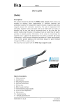
This manual describes the products of SMA1 series.
The purpose of these sensors is to measure linear
displacements on industrial machines and
automation systems. The measurement system
includes a magnetic tape and a magnetic sensor.
The tape is magnetized with magnetic north-south
poles. The poles are coded thus the magnetic tape is
absolute. As the sensor is moved along the magnetic
tape, it detects the displacement and produces an
absolute SSI output or BiSS output signal (B -mode
or C-mode) and an additional 1Vpp sin-cosine signal
for speed feedback.
The sensor has to be matched with MTA1 magnetic
tape.
•
•
Electrical safety
•
•
•
-
Chapters
1
2
3
4
5
6
7
8
9
10
11
12
Mechanical safety
•
Safety summary
Identification
Mounting instructions
Position errors diagnostics
Electrical connections
SSI interface
BiSS B-mode interface (SMA1-…/S682)
BiSS C-mode interface
1Vpp outputs
Dimensional drawing
Maintenance
Troubleshooting
MAN SMA1 E 2.3.doc
switch OFF the voltage before connecting the device;
connect according to the chapter “Electrical connections”;
according to the 89/336/CEE norm on
electromagnetic
compatibility,
following
precautions must be taken:
before handling and installing, discharge electrical charge
from your body and tools which may come in touch with
the device;
power supply must be stable without noise, install EMC
filters on device power supply if needed;
always use shielded and twisted cables if possible;
avoid cables runs longer than necessary;
avoid running the signal cable near high voltage power
cables;
mount the device as far as possible from any capacitive or
inductive noise source, shield the device from noise source
if needed;
minimize noise by connecting shield or connector housing
to ground (GND). Make sure that ground (GND) is not
affected by noise. The shield connection point to ground
can be situated both on the device side and on user’s side.
The best solution to minimize the interference must be
carried out by the user.
•
•
•
•
•
•
install according to the chapter “Mounting instructions”
with stationary mechanics parts;
do not disassemble the device;
do not tool the device;
do not subject the device to knocks or shocks;
protect the system against solvents and substances
damaging it;
respect the environmental characteristics of the product;
be sure that the system is mounted where hard or sharp
objects (e.g. metal chips) do not come into contact with
the magnetic tape and the bottom of the sensor head. If
these conditions cannot be avoided provide a wiper or
pressurized air.
1
PH SYSTEMS - www.phsystems.be - [email protected]
www.lika.it
www.lika.biz
SMA1
2 - Identification
4 - Position errors diagnostics
The device can be identified by the label's data
(ordering code, serial number). This information is
listed in the delivery document. For technical
features of the product, refer to the technical
catalogue.
In case of bad alignment between of the sensor on
the tape, the following errors may occur during
power-on or operation:
• during power-on: "LED on", invalid data could
be transmitted until the sensor is correctly
aligned (LED off);
• during operation: last valid position is freezed
until the next valid position on the tape is
detected.
3 - Mounting instructions
3.1 Magnetic tape
Install sensor and magnetic tape according to the
above figure.
The arrow shows standard counting direction.
The system doesn't work if mounted incorrectly.
4.1 Diagnostic LED
When lit, the LED indicates an incorrect alignment
of the sensor to the tape, like:
• gap between sensor and tape out of tolerance
(see fig. 6)
• incorrect installation of sensor
• sensor overlaps the tape
3.2 Sensor mounting
With BiSS interface, LED status is transmitted on nE
bit.
Note:
"LED off" confirms correct detection of absolute
position, but not correct detection of sine-cosine
signals.
fig.6
Sensor can be fixed by means of two M4 screws
over the buttonholes. Make sure that the gap
between sensor and tape is in respect with (fig. 6)
along the total measuring length. Avoid contact
between the parts. You can check planarity and
parallelism between sensor and magnetic tape using
a feeler gauge.
The allowed gap (D) is 0.1 mm ÷ 0.3 mm
(0.004” ÷ 0.012”).
Do not use the cover strip, it would cause excessive
gap between sensor and tape surface.
MAN SMA1 E 2.3.doc
2
PH SYSTEMS - www.phsystems.be - [email protected]
www.lika.it
www.lika.biz
SMA1
5 - Electrical connections
Connections
Colour
Violet
Yellow
Grey
Pink
Green
Brown
Red
Black
Brown/ Green
White/ Green
White
Blue
*:
+10Vdc +30Vdc
+5Vdc
+5Vdc
6 - SSI interface
SMA1-BA-5-…
SMA1-GA-5-…
Function
Clock in +
Clock in Data out +
Data out A
/A
B
/B
+Vdc *
0Vdc GND
not connected
not connected
for standard SMA1
for SMA1-…/S188
for SMA1-…/S682
6.1 LSB right aligned protocol
The type of transmission protocol is "right aligned"
with a length of 25 bits. The transmission starts with
MSB (most significant bit) and ends with LSB (less
significant bit).
The device uses 20 bits for the position, unused bits
are set to 0 (zero).
The output code of the sensor can be GRAY or
BINARY (see ordering code).
The measuring step is equal to the resolution (5µm).
Position structure:
bit
24…20
00000
value
19
MSB
…
…
0
LSB
6.2 Recommended transmission rates
The SSI interface has a frequency of data
transmission from 100 kHz to 1 MHz.
The CLOCK signal and DATA signal follow the “EIA
standard RS-422”.
The transmission rate (baud rate) depends on the
length of cables.
Specifications of the cable
T12 cable (TKD 4444)
Twisted pair 4 x 2 x 0,14mm2 + 4 x 0,25mm2
Screening
: braided
Outside Ø
: Ø 6.1 mm (Ø 0.24”)
Resistance
: according to DIN VDE 0295 class 6
according to IEC
Cable length
< 50 m
< 100 m
< 200 m
< 400 m
Baud rate
< 400 kHz
< 300 kHz
< 200 kHz
< 100 kHz
The time interval between two Clock sequence
transmissions must be at least 16µs ( Tp > 16µs ).
MAN SMA1 E 2.3.doc
3
PH SYSTEMS - www.phsystems.be - [email protected]
www.lika.it
www.lika.biz
SMA1
7 - BiSS B -mode interface
SMA1-I7-…/S682
7.3 Sensor mode
Sensor mode (32 bits) is composed by position value,
1 error bit (nE), 1 warning bit (nW) and CRC
checking (6 bits).
SMA1 is a slave device according to “BiSS B-mode
interface” and “Standard encoder profile”.
Refer to the official BiSS website for all information
not listed in this manual (www.biss-interface.org).
The sensor works in point-to-point configuration,
and has to be installed on a “single master, single
slave” network (not on a “single master, multi slave”
network).
CLOCK and DATA signals level are according to the
“EIA standard RS-422”.
Sensor data structure:
Start
DATA
31…8
7
6
position error warning
Stop
5…0
CRC
Attention: Multi-Cycle-Data bit (MCD) is not used,
the master mustn’t ask it!
7.1 Communication
The BiSS B-mode protocol uses two types of data
transmission protocols:
• Register Mode: used to read or write data into
the registers of the slave.
• Sensor mode: used to send process data from
the slave to the master.
Position (24 bits)
Process data transmitted from slave to master.
The transmission starts with MSB (most significant
bit) and ends with LSB (less significant bit).
bit
31…28
27
…
8
0000
MSB
…
LSB
value
To see position value in mm, multiply the data value
received for the resolution (see 4Dhex register).
7.2 Register Mode
See official BiSS documents for complete structure.
Main control data is described in this chapter.
Error (1 bit)
Communicates an error of the slave.
nE = “1”: correct status (no error)
= “0”: error status: tape not read.
Check gap between sensor and tape,
planarity and parallelism of the system.
Register address (7 bits)
Specifies the register to read or write.
DATA (8 bit)
Write register: value to write into the register
(transmitted from master to slave).
Read register: value read from the register
(transmission from slave to master).
Data bit structure:
bit
7
…
…
0
MSB
…
…
LSB
Warning (1 bit)
Not used (nW = “1”)
CRC (6 bits)
Correct transmission control (inverted output).
Polynomial: X6 +X1+1 (binary: 1000011)
CRC (4 bits)
Correct transmission control (inverted output).
Polynomial: X4+X1+1 (binary: 10011)
Logic circuit:
Logic circuit:
2nd
stage
1st
stage
X0
3rd
stage
X1
X2
2nd
stage
1st
stage
4th
stage
X0
X3
3rd
stage
X1
X3
5th
stage
X4
6th
stage
X5
Input Data (starts from MSB)
Input Data (starts from MSB)
MAN SMA1 E 2.3.doc
X2
4th
stage
4
PH SYSTEMS - www.phsystems.be - [email protected]
www.lika.it
www.lika.biz
SMA1
7.4 Used registers
Register (hex)
42…43
44…47
48
49
4D
51…53
55
58
78…7D
7E…7F
48 Command [wo]
Value
Function
Normal
operation
00
01
Save parameters on EEPROM
02
Save and activate Preset/ Offset
04
Load and save default parameters
Function
Profile ID
Serial number
Command
Configuration
Absolute resolution
Preset/ Offset
Device type
SIN/COS resolution
Device ID
Manufacturer ID
This register will set back to "00" automatically.
Wait min. 30ms (EPROM writing time) before using
the next function.
49 Configuration [rw]
Bit
Function
bit=0
bit=1
0
SELSSI
SSI
BiSS
1
Set preset/ offset
Offset
Preset
2
Enable preset/ offset
Disable
Enable
3
Not used
4
Not used
5
Output code
Gray
Binary
6
Inverted
Counting direction * Standard
7
Not used
*: related to absolute position (not to sin/cos signal)
All registers in this chapter are listed according to
the following outline:
Address Function name [access]
Description of the function and default value.
- Address: register address in hexadecimal values.
- Access:
ro = read only
rw = read and write
wo = write only
- Default parameter values are written in bold.
The new setting will be active immediately after
transmission. Use the function “Save parameters”
(set “01” register 48) to store the new value.
Default = 20h
42…43 Profile ID [ro]
These registers contain the identification code of
the used profile.
Register
42
43
28
14
Hex
See “Standard encoder profile”, “data format”,
“Variant 0-24”.
4D Absolute resolution [rw]
Contains the resolution of absolute sensor.
64hex : Res.=0.1mm (max position = 00 FF FFh)
32hex : Res.=0.05mm (max position = 01 FF FFh)
0Ahex : Res.=0.01mm (max position = 07 FF FFh)
05hex : Res.=0.005mm (max position = 0F FF FFh)
44…47 Serial number [ro]
These registers contain the serial number (hex value)
of the device.
reg.44: year of production
reg.45: week of production
reg.46, 47: progressive serial number
The new setting will be active immediately after
transmission. Use the function “Save parameters”
(set “01” register 48) to store the new value.
After the modification of reg.4D Preset and Offset
values have to be updated according to the new
resolution!
Default = 05h.
MAN SMA1 E 2.3.doc
5
PH SYSTEMS - www.phsystems.be - [email protected]
www.lika.it
www.lika.biz
SMA1
51…53 Preset/Offset [rw]
This function has to be enabled by setting reg.49 bit
2 = ”0”. Setting of Preset or Offset register can be
carried out only when the sensor is not moving.
7.5 Application note
Device communication characteristics:
Parameter
Min
Clock Frequency Sensor Mode 350KHz
Clock Frequency Register Mode 50KHz
Preset: any desired position value can be set (e.g.
"0", zero setting)
Offset: adds an offset to actual position.
Position = actual position + Offset.
Preset/Offset structure:
Reg.
51
52
MSB
…
223- 216
215 - 28
Timeout Sensor Mode
Timeout Register mode
1.5µs
15.5µs
Max
10MHz
250KHz
3.5µs
17.5µs
7.6 Examples
All values are hexadecimal.
53
LSB
27 - 20
Set configuration register:
DATA Tx = 06h: set preset, Binary output code,
inverted counting direction.
Function
ADR
DATA Tx
write register
49
60
Use the function “Save and activate Preset/ Offset”
(set “02” register 48) to store and activate the new
value.
The max. allowed Preset values are depending on
the resolution.
save parameters
Set Preset:
Preset = 01 86 A0h
Function
resolution = 0.1 à max preset =00 FF FFh (16bit)
resolution = 0.05 à max preset =01 FF FFh (17bit)
resolution = 0.01 à max preset =07 FF FFh (19bit)
resolution = 0.005à max preset =0F FF FFh (20bit)
Default = 00h.
write register
save and active
Preset
55 Device type [ro]
Describes the type of device.
Default = 06h: linear encoder BiSS + SIN/COS
48
01
ADR
51
52
53
DATA Tx
01
86
A0
48
02
58 SIN/COS resolution [ro]
Describes the period of sin/cos signal
Default = 01h: resolution = 1mm
78…7D Device ID [ro]
These registers contain the Device ID.
Reg.
78
79
7A
7B
53
4D
41
31
Hex
S
M
A
1
ASCII
xx: software version
7C
xx
-
7D
xx
-
7E…7F Manufacturer ID
These registers contain the Manufacturer ID.
Reg.
7E
7F
4C
69
Hex
L
i
ASCII
Li = Lika Electronic.
MAN SMA1 E 2.3.doc
6
PH SYSTEMS - www.phsystems.be - [email protected]
www.lika.it
www.lika.biz
SMA1
8 - BiSS C -mode interface
SMA1-I7-… standard
8.3 Single Cycle Data
SCD (32 bits) is composed by position value, 1 error
bit (nE), 1 warning bit (nW) and CRC checking (6
bits).
SMA1 is a slave device according to “BiSS C-mode
interface” and “Standard encoder profile”.
Refer to the official BiSS website for all information
not listed in this manual (www.biss-interface.org).
The sensor works in point-to-point configuration,
and has to be installed on a “single master, single
slave” network (not on a “single master, multi slave”
network).
CLOCK and DATA signals level are according to the
“EIA standard RS-422”.
SCD structure:
bits
31…8
function position
5…0
CRC
Error (1 bit)
Communicates an error of the slave.
nE = “1”: correct status (no error)
= “0”: error status: tape not read.
Check gap between sensor and tape,
planarity and parallelism of the system.
8.2 Communication
The BiSS C-mode protocol uses two types of data
transmission protocols:
•
6
warning
Position (24 bits)
Process data transmitted from slave to master.
The transmission starts with MSB (most significant
bit) and ends with LSB (less significant bit).
bit
31…28
27
…
8
0000
MSB
…
LSB
value
To see position value in mm, multiply the data value
received for the resolution (see 4Dhex register).
8.1 XML file
The product is supplied with XML file
idbiss4C69.xml (see enclosed support or
www.lika.biz > PRODUCTS > LINECOD > SMA1).
Install XML file on BiSS master device.
•
7
error
Single Cycle Data (SCD): is the primary data
transmission protocol. It's used to send process
data from the slave to the master.
Control Data (CD): transmission of a single bit
following the SCD data. It is used to read or
write data into the registers of the slave.
Warning (1 bit)
Not used (nW = “1”)
CRC (6 bits)
Correct transmission control (inverted output).
Polynomial: X6 +X1+1 (binary: 1000011)
Logic circuit:
2nd
stage
1st
stage
X0
3rd
stage
X1
X2
4th
stage
X3
5th
stage
X4
6th
stage
X5
Input Data (starts from MSB )
MAN SMA1 E 2.3.doc
7
PH SYSTEMS - www.phsystems.be - [email protected]
www.lika.it
www.lika.biz
SMA1
8.4 Control Data CD
See official BiSS documents for complete CD
structure: “Protocol description C-mode”.
Main control data is described in this chapter.
8.5 Used registers
Register (hex)
42…43
44…47
48
49
4D
51…53
55
58
78…7D
7E…7F
Register address (7 bits)
Specifies the register to read or write.
RW (2 bits)
RW = “01” : write register
RW = “10” : read register
All registers in this chapter are listed according to
the following outline:
DATA (8 bit)
Write register: value to write into the register
(transmitted from master to slave).
Read register: value read from the register
(transmission from slave to master).
Data bit structure:
bit
7
MSB
…
…
…
…
Address Function name [access]
Description of the function and default value.
- Address: register address in hexadecimal values.
- Access:
ro = read only
rw = read and write
wo = write only
- Default parameter values are written in bold.
0
LSB
42…43 Profile ID [ro]
These registers contain the identification code of
the used profile.
CRC (4 bits)
Correct transmission control (inverted output).
Polynomial: X4+X1+1 (binary: 10011)
Register
42
43
28
14
Hex
See “Standard encoder profile”, “data format”,
“Variant 0-24”.
Logic circuit:
2nd
stage
1st
stage
X0
3rd
stage
X1
4th
stage
X2
44…47 Serial number [ro]
These registers contain the serial number (hex value)
of the device.
reg.44: year of production
reg.45: week of production
reg.46, 47: progressive serial number
X3
Input Data (starts from MSB)
MAN SMA1 E 2.3.doc
Function
Profile ID
Serial number
Command
Configuration
Absolute resolution
Preset/ Offset
Device type
SIN/COS resolution
Device ID
Manufacturer ID
8
PH SYSTEMS - www.phsystems.be - [email protected]
www.lika.it
www.lika.biz
SMA1
48 Command [wo]
Value
Function
Normal
operation
00
01
Save parameters on EEPROM
02
Save and activate Preset/ Offset
04
Load and save default parameters
51…53 Preset/Offset [rw]
This function has to be enabled by setting reg.49 bit
2 = ”0”. Setting of Preset or Offset register can be
carried out only when the sensor is not moving.
Preset: any desired position value can be set (e.g.
"0", zero setting)
Offset: adds an offset to actual position.
Position = actual position + Offset.
This register will set back to "00" automatically.
Wait min. 30ms (EPROM writing time) before using
the next function.
Preset/Offset structure:
Reg.
51
52
MSB
…
223- 216
215 - 28
49 Configuration [rw]
Bit
Function
bit=0
bit=1
0
Not used
1
Set preset/ offset
Offset
Preset
2
Enable preset/ offset
Disable
Enable
3
Not used
4
Not used
5
Output code
Gray
Binary
6
Counting direction * Standard Inverted
7
Not used
*: related to absolute position (not to sin/cos signal)
Use the function “Save and activate Preset/ Offset”
(set “02” register 48) to store and activate the new
value.
The max. allowed Preset values are depending on
the resolution.
resolution = 0.1 à max preset =00 FF FFh (16bit)
resolution = 0.05 à max preset =01 FF FFh (17bit)
resolution = 0.01 à max preset =07 FF FFh (19bit)
resolution = 0.005à max preset =0F FF FFh (20bit)
Default = 00h.
The new setting will be active immediately after
transmission. Use the function “Save parameters”
(set “01” register 48) to store the new value.
Default = 20h
55 Device type [ro]
Describes the type of device.
Default = 06h: linear encoder BiSS + SIN/COS
4D Absolute resolution [rw]
Contains the resolution of absolute sensor.
64hex : Res.=0.1mm (max position = 00 FF FFh)
32hex : Res.=0.05mm (max position = 01 FF FFh)
0Ahex : Res.=0.01mm (max position = 07 FF FFh)
05hex : Res.=0.005mm (max position = 0F FF FFh)
58 SIN/COS resolution [ro]
Describes the period of sin/cos signal
Default = 01h: resolution = 1mm
78…7D Device ID [ro]
These registers contain the Device ID.
Reg.
78
79
7A
7B
53
4D
41
31
Hex
S
M
A
1
ASCII
xx: software version
The new setting will be active immediately after
transmission. Use the function “Save parameters”
(set “01” register 48) to store the new value.
After the modification of reg.4D Preset and Offset
values have to be updated according to the new
resolution!
Default = 05h.
MAN SMA1 E 2.3.doc
53
LSB
27 - 20
7C
xx
-
7D
xx
-
7E…7F Manufacturer ID
These registers contain the Manufacturer ID.
Reg.
7E
7F
4C
69
Hex
L
i
ASCII
Li = Lika Electronic.
9
PH SYSTEMS - www.phsystems.be - [email protected]
www.lika.it
www.lika.biz
SMA1
8.6 Application note
Data transmission:
Parameter
Clock Frequency
Value
min 200KHz, max 10MHz
auto adaptation to clock,
max 16µs
BiSS Timeout
Internal position update
frequency
6KHz
8.7 Examples
All values are hexadecimal.
Set configuration register:
DATA Tx = 06h: set preset, Binary output code,
inverted counting direction.
Function
ADR
DATA Tx
write register
49
60
save parameters
Set Preset:
Preset = 01 86 A0h
Function
write register
save and active
Preset
MAN SMA1 E 2.3.doc
48
01
ADR
51
52
53
DATA Tx
01
86
A0
48
02
10
PH SYSTEMS - www.phsystems.be - [email protected]
www.lika.it
www.lika.biz
SMA1
9 - 1Vpp sine/cosine output signals
10 - Dimensional drawing
The frequency of output signals is proportional to
the displacement speed of the sensor.
Sensor and tape
A and B signals (standard counting direction)
P is the electrical period length:
P = 1mm
9.1 Output signals voltage level
The voltage level refers to the difference between
normal and inverted signal (differential).
11 - Maintenance
The magnetic measurement system doesn't need
any particular maintenance but as with all precision
devices it must be handled with care. From time to
time we recommend the following operations:
• check the gap between sensor and magnetic
tape along the measuring length. Wear of the
machine may increase the tolerances;
• the surface of the magnetic tape should
occasionally be cleaned using a soft cloth to
remove dust, chips, moisture etc.
Recommended input circuit:
Sensor
Input circuit
VREF = 2,5V ± 0,5V
MAN SMA1 E 2.3.doc
VA = 1Vpp · Av
Av = R2/R1
11
PH SYSTEMS - www.phsystems.be - [email protected]
www.lika.it
www.lika.biz
SMA1
12 - Troubleshooting
The following list shows some typical errors that
occur during installation and operation of the
magnetic measurement system.
Problem:
The system doesn't work (no pulse output):
•
•
•
•
The tape or sensor has been mounted incorrectly
(the active part of the tape doesn't face the
sensor's active side). See chapter 3 for correct
installation. LED is lighted.
A magnetic piece or tape is in between the
sensor and the tape. Only non-magnetic
materials are allowed between sensor and tape.
LED is lighted.
The sensor touches the tape because tolerance
gap between sensor and tape are not observed.
Check sensor's active side if damaged.
The sensor has been damaged by short circuit or
wrong connection.
Rev.
0
Man.Vers.
1.0
1
1.1
2
0
1.2
2.0
1
2.1
2
3
2.2
2.3
Description
1^ issue
Add CRC calculations (chap.6.1.5)
“Operating parameters”: default=0
Chap.5 update
SW update
Add SSI interface
Electrical connections (chap.5) update
Note about MCD bit (chap.7.3)
Chap. 6 update
Problem:
The measured values are inaccurate or not present
at some positions:
•
•
•
•
•
The gap between sensor and tape is not
observed along the total measurement length
(see chap. 4) or the sensor is not mounted
correctly to the tape (see chap. 3).
LED is lighted.
The connection cable runs near to high voltage
cables or the shield is not connected correctly.
The frequency of your clock is set too high or
too low and the sensor cannot synchronize
correctly (see chap. 6).
A section of the magnetic tape has been
damage mechanically or magnetically along the
measuring length.
The measuring error is caused by torsion of the
machine structure. Check parallelism and
symmetry of machine movement.
Lika Electronic
Via S. Lorenzo, 25 - 36010 Carrè (VI) - Italy
Tel. +39 0445 382814
Fax +39 0445 382797
Italy : eMail [email protected] - www.lika.it
World : eMail [email protected] - www.lika.biz
MAN SMA1 E 2.3.doc
12
PH SYSTEMS - www.phsystems.be - [email protected]
www.lika.it
www.lika.biz