1
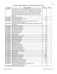
UMS :Overview UMS Overview CONTENTS Introduction .................................................................................................................................................................. 1 Principal system components ....................................................................................................................................... 1 Table of Components ................................................................................................................................................ 1 Measurement Tank ................................................................................................................................................... 2 Motion Control Actuators and Frame ....................................................................................................................... 2 Description............................................................................................................................................................ 2 Axis labelling convention ...................................................................................................................................... 2 Two-rotational axes gimbal mount ........................................................................................................................... 3 Axis labelling convention ...................................................................................................................................... 3 Stepper motor drive control unit .............................................................................................................................. 3 Emergency Stop System............................................................................................................................................ 4 Filling the tank ...................................................................................................................................................... 4 Refilling the tank ................................................................................................................................................... 4 Digital Storage Oscilloscope ...................................................................................................................................... 5 Host PC ...................................................................................................................................................................... 5 UMS Software ........................................................................................................................................................... 5 System setup ................................................................................................................................................................ 6 Parts List ....................................................................................................................................................................... 7 UMS Overview INTRODUCTION UMS is a custom built test tank system for making a variety of ultrasound measurements. This manual describes the configuration and connection of the hardware part of the system. For information relating to the use of the control and post processing software, please refer to the appropriate user manual. Items relevant to the safe operation of the UMS system will be highlighted as per this entry. PRINCIPAL SYSTEM COMPONENTS IMPORTANT NOTE: For user convenience, the components of the UMS are fully assembled and wired together. Unpacking the shipment crate is therefore likely to require several people. TABLE OF COMPONENTS Description Figure Quantity Water Tank - 1 Fully assembled frame with stepper motor control and wired motion actuator system - Stepper Motor Drive Control Unit Door Handle - 1 Oscilloscope - 1 Host PC - 1 PC Monitor - 1 UMS Software V3.0 - 1 Hydrophone rod holder 1 1 2-axis of rotation Transducer Mount 2 1 Water Treatment System complete with deionisation cartridge and hoses - 1 Thermocouple based temperature monitoring System - 1 1 1 UMS Overview MEASUREMENT TANK The ultrasonic measurement tank is constructed from 19mm thick Perspex (Plexiglas) with fully bonded seams and joints The measurement tank should be positioned within the test tank frame. It is particularly important to ensure the surface remains flat once the tank is full of water. Insufficiently reinforced work surfaces can bend or bow under the weight of a full water tank, which results in the tank being unevenly supported. This is likely to cause additional stressing of the joints of the tank and could results in the tank fracturing. Another possible cause of fracture can occur if the surface is not flat, or if a small object (e.g. piece of grit), is trapped between the bottom of the tank and the work surface. As a precautionary measure, a layer of high-density closed cell foam (e.g. Plastazote™ / Evazote™) can be placed immediately under the measurement tank to ensure the load of the tanks is more evenly distributed. MOTION CONTROL ACTUATORS AND FRAME DESCRIPTION This component is principally concerned with the movement of the hydrophone within the measurement tank. There are four linear motion stages (3 powered, 1 slave). Each linear actuator is based upon a 2mm pitch ball screw that is driven by a stepping motor. Closed-loop control is provided by a load mounted linear magnetic encoder giving a read out positional resolution of 1µm. With all stepper motor driven systems there exists the possibility that the number of steps actually moved by the drive will not be the same as the number steps requested by the drive controller. This generally results in the actuator not moving as far as expected. When the encoders are activated their output is fed back to the drive controller. If there is a difference between the distance moved by the actuator, and that initially requested, the drive controller calculates the necessary correction and automatically moves the drive as appropriate. The encoder deadband is set by default to 5 µm giving positional accuracy of +/- 5 µm. As a safety precaution all drives have two limit switches that can be used to prevent the actuator from moving beyond particular user definable positions. These can be used to prevent the hydrophone from being driven into the walls of the tank, or into obstacles placed within the tank AXIS LABELLING CONVENTION To prevent confusion when identifying axes, the following conventions are adopted: • The Z-axis (in keeping with standard acoustics nomenclature) is the acoustic axis of the transducer. For vertically mounted systems (transducer firing top down, or bottom up) the Z-axis will be the vertical axis. For horizontally mounted systems, the Z-axis is the longest horizontal axis of the tanks • The X-axis is always defined as the axis which crosses the tank • The Y-axis is thus defined as the longitudinal axis of the tank (for vertically mounted systems) or the vertical axis (for horizontally mounted systems). All axes adopt the convention that the positive direction is away from the actuator motor. 2 UMS Overview TWO-ROTATIONAL AXES GIMBAL MOUNT All of the mechanical components of the gimbal mount are either made of stainless steel, anodised aluminium or water tolerant plastics. However, the DC servo motors and their controller units are not waterproof, and present a safety risk if immersed. Therefore the gimbal mount is fitted with an immersion sensor that will act as an ALLAXIS EMERGENCY STOP when activated. The immersion sensor is positioned so as to allow maximum rotational adjustment range, whilst protecting the motors from immersion. Under no circumstances should the position of the immersion sensor be altered by the user. Particularly care should be taken when removing the gimbal mount from the system. The gimbal mount should never be detached from the system whilst electrical power is being supplied to the stepper motor drive control unit. AXIS LABELLING CONVENTION Once X and Y axis have been identified the two rotational axes on the gimbal are simply identified as rotation about the X-axis (Abt_X) and about the Y-axis (Abt_Y). STEPPER MOTOR DRIVE CONTROL UNIT This unit contains the stepper motor drive controllers and their associated power supplies. It also contains the temperature monitoring system. Each motion actuator has its own dedicated drive controller within the cabinet. These controllers deal with all aspects of motion control. In addition to supplying power to the stepper motors, they also implement the actions required by the limit or emergency stop switches, as well as administering position maintenance instructions when the system is used with drive encoders. The drive control unit is mains powered, and is fitted with a door cut-out switch that interrupts the mains power whenever the cabinet door is opened. Opening the door will immediately trigger the switch and cut power to the stepper motors on the motion actuators (note the drive controllers remain active via a 24 V dc “logic” supply). This is clearly undesirable if the UMS is in the middle of a measurement, and the cabinet door should therefore be kept shut at all times. A black plastic handle for the cabinet is included with the UMS. This handle can be removed from the unit to prevent unauthorised access and should be stored safely when not in use. The drive control unit should ALWAYS be connected to the mains electricity supply by means of a Residual Current Circuit Breaker (RCCB). The RCCB should also be tested every time that the system is used. This unit is mains powered and whilst the enclosure is splash proof, it is not fully waterproof. Therefore this unit should NOT be placed anywhere near direct sources of water 3 UMS Overview EMERGENCY STOP SYSTEM The UMS test tank system is equipped with an emergency stop (E-STOP) switch. The switch is connected to the control box by a cable sufficiently long to be positioned close to the user at all times. When pressed the switch latches in the “ESTOP Active” position. Once safe to do so, the ESTOP can be released by twisting the red pushbutton in the direction indicated on it. The consequences of pressing the ESTOP are as follows: 1. Power is immediately cut to the stepper motors on the linear axes and if applicable the stepper motor controlled rotary table. a. Logic power supply to the stepper controllers and encoders is maintained allowing the system to maintain a record of its position. 2. All power is cut to the optional Gimbal mount (assuming the gimbal mount wiring is integral to the system, where a gimbal mount has been supplied as an add-on, this may not apply). a. Note: Since the motors used in the current gimbal mount are servos, they can be “backdriven” when power is removed. Therefore great care should be taken to avoid mounting heavy items on the gimbal above its pivot point (as this arrangement is inherently unstable and removing power could cause the load to flip and potentially cause damage to the system). 3. The software process which was running will detect the ESTOP activation and “pause” its execution. A dialogue is displayed on the screen indicating that the ESTOP has been activated. The user can then clear this dialogue by selecting the appropriate option once the ESTOP has been released. FILLING THE TANK The tank should be filled with deionisation water. REFILLING THE TANK The test tank should be refilled when necessary. How regularly the water in the test tank requires changing will be largely dependent on the size of the tank and the environment in which the test tank is situated. The user will be best placed to judge if the water has become discoloured over time, or has “re-ionised”. For precise control of the water quality it is recommended that the user procures both a dissolved air (and at least dissolved oxygen) and conductivity meter and closely monitors these water properties. The conductivity of the degassed water should be less than 4 uS/cm (1) and the dissolved oxygen content between 5-8 ppm or <4 ppm for high powers (>10W) (2). At Precision Acoustics the test tank water is changed approximately every 3 to 6 months. (1) IEC 62127 part 1 (2) NEMA UD-2 4 UMS Overview DIGITAL STORAGE OSCILLOSCOPE The UMS is designed to operate with a range of digital storage oscilloscopes from Agilent, Tektronic and Lecroy. These high specification digital storage oscilloscopes (DSO) are used for all data acquisition and also handle all the data transfer back to the host PC by means of onboard Ethernet or GPIB communication. Support for other oscilloscopes may be available , for further information please contact us with your specific model. . HOST PC This PC runs the UMS Software that is at the heart of the UMS. If you have purchased a PC for this purpose from PAL, all the necessary software will have been pre-installed. If however you are using your own PC then further set up will be required. Once assembled, the PC will use a USB port to interface with the Stepper Motor Drive Control Unit (section 2.4). The PC communicates with the DSO via an Ethernet (RJ45) connector. All data acquired by the DSO is also passed back to PC for storage and subsequent post processing. UMS SOFTWARE The ultrasonic measurement system is controlled from the Host PC by means of dedicated LabVIEW based software. If you intend to use the Labview source code to write your own software, you must use at least LabVIEW version 8.6.1. UMS sofware application controls all aspects of the operation of the system including: • Initialisation of communication interfaces via the LeCroy VISA Passport for communication with the DSO • Motion of the stepper motor actuators • Waveform acquisition by the oscilloscope and subsequent transfer of data to the host PC • Acquisition and storage of temperature data • Archival and post-processing of acquired data LabVIEW is a registered trade mark of National Instruments Inc 5 UMS Overview SYSTEM SETUP A schematic overview of the installation of the UMS system is shown in the figure below. Host PC Motion Control UMS Software Acquisition Control Trigger Oscilloscope Stepper Motor Drive Control Unit Function Generator (Not Supplied) Drive Signal Motion Control Actuators and Frame Z Axis X Axis Y Axis Hydrophone Signal Hydrophone in Hydrophone Mount Motion Control Measurement Tank Ultrasonic Source in Transducer Mount 6 UMS Overview PARTS LIST Description Main test tank parts: Anodised aluminium gantry framework and fixings Water tank Linear actuators Stepper motors on linear axes Stepper motor controllers Stepper motor power supply Linear magnetic encoder scales Linear magnetic encoder read head Reference markers for Linear magnetic encoder scales Quantit y Manufacture r Part number Supplier 1 Minitec n/a 1 Angloplas 4 Velmex Oriental 3 Motor 3 Parker 1 Parker 3 Renishaw 3 Renishaw n/a BiSlide PK266 and PK296 ViX250/500IM XL PSU LM10 LM10 LG Motion/Minitec Precision Acoustics Ltd LG Motion 3 Renishaw LM10 7 LG Motion LG Motion LG Motion Precision Acoustics Precision Acoustics Precision Acoustics UMS Overview 8