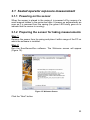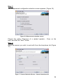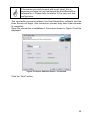
1
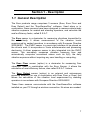
Evec, Evec Floor et Evec Detect
Whole-Body Vibration Dosimeter Range
User Manual
EvecSensorDuo Software for PC
Version 2.0
GLOSSARY
Bluetooth
EMC
PDA
USB
Set of technologies allowing wireless data transmission
over short distances
Electromagnetic Compatibility
Personal digital assistant
Universal Serial Bus
i
TABLE OF CONTENTS
SECTION 1 - DESCRIPTION ............................................................. 7
1.1 GENERAL DESCRIPTION ............................................................... 7
SECTION 2 - INSTALLING AND CONFIGURING ....................... 10
2.1 CHARGING THE SENSOR BATTERY(IES) ..................................... 10
2.2 PREREQUISITES ........................................................................... 11
2.3 CONFIGURING THE BLUETOOTH® WIRELESS LINK .................... 11
2.3.1 IS BLUETOOTH® INSTALLED ON YOUR PC?............................. 12
2.3.2 BLUETOOTH® PAIRING AND COMMUNICATION PORT SETUP .. 13
2.4 INSTALLING THE EVECSENSORDUO SOFTWARE ....................... 18
2.5 CONFIGURING THE EVECSENSORDUO SOFTWARE - ADDING A
SENSOR ................................................................................................. 18
SECTION 3 - OPERATION............................................................... 22
3.1 SEATED OPERATOR EXPOSURE MEASUREMENT ....................... 23
3.1.1 POWERING ON THE SENSOR .................................................... 23
3.1.2 PREPARING THE SENSOR FOR TAKING MEASUREMENTS ........ 23
3.1.3 INSTALLING THE SENSOR ON THE SEAT ................................... 28
3.1.4 OPERATING ............................................................................... 29
3.1.5 ACCESSING MEASUREMENT RESULTS ..................................... 30
3.1.6 SWITCHING OFF THE SENSOR .................................................. 37
3.2 STANDING OPERATOR EXPOSURE MEASUREMENT ................... 38
3.2.1 POWERING ON THE SENSORS .................................................. 38
3.2.2 PREPARING THE SENSORS FOR TAKING MEASUREMENTS ..... 38
3.2.3 INSTALLATION OF THE SENSORS.............................................. 42
3.2.4 OPERATING ............................................................................... 44
3.2.5 ACCESSING MEASUREMENTS RESULTS ................................... 45
3.2.6 SWITCHING OFF THE SENSORS ................................................ 52
3.3 MEASUREMENT OF S.E.A.T. FACTORS ..................................... 53
3.3.1 INTRODUCTION ......................................................................... 53
3.3.2 POWERING ON THE SENSORS .................................................. 53
ii
3.3.3 PREPARING THE SENSORS TO TAKE MEASUREMENTS ........... 53
3.3.4 INSTALLATION OF THE SENSORS.............................................. 57
3.3.5 OPERATING ............................................................................... 59
3.3.6 ACCESSING MEASUREMENTS RESULTS ................................... 60
3.3.7 SWITCHING OFF THE SENSORS ................................................ 68
3.4 T0 TIME INTERVAL SETTING........................................................ 69
3.5 CHARGING THE SENSOR BATTERY ............................................. 71
SECTION 4 - EVECSENSOR DEVICE CHARACTERISTICS .. 72
4.1
4.2
4.3
4.4
4.5
4.6
4.7
4.8
4.9
4.10
4.11
COMPLIANCE WITH STANDARDS................................................. 72
FREQUENCY WEIGHTINGS .......................................................... 72
EXTRAPOLATION – PARTIAL MEASUREMENT............................ 72
SENSOR DYNAMICS..................................................................... 74
STORAGE CAPACITY AND AUTONOMY....................................... 75
PHYSICAL SENSOR CHARACTERISTICS ..................................... 75
ENVIRONMENT ............................................................................. 75
MEASUREMENT RESULTS ........................................................... 75
CHARGER ..................................................................................... 75
WIRELESS LINK ........................................................................... 75
ELECTROMAGNETIC COMPATIBILITY ......................................... 76
SECTION 5 - EVECFLOOR DEVICE CHARACTERISTICS ...... 77
5.1
5.2
5.3
5.4
5.5
5.6
5.7
5.8
5.9
5.10
COMPLIANCE WITH STANDARDS................................................. 77
FREQUENCY WEIGHTINGS .......................................................... 77
SENSOR DYNAMICS..................................................................... 78
STORAGE CAPACITY AND AUTONOMY....................................... 79
PHYSICAL SENSOR CHARACTERISTICS ..................................... 79
ENVIRONMENT ............................................................................. 79
MEASUREMENT RESULTS ........................................................... 79
CHARGER ..................................................................................... 79
WIRELESS LINK ........................................................................... 79
ELECTROMAGNETIC COMPATIBILITY ......................................... 80
SECTION 6 - EVEC DETECT DEVICE CHARACTERISTICS .... 81
iii
6.1
6.2
6.3
6.4
6.5
6.6
6.7
6.8
COMPLIANCE WITH STANDARDS................................................. 81
DYNAMIC DEVICE CHARACTERISTICS ......................................... 81
STORAGE CAPACITY AND AUTONOMY....................................... 81
PHYSICAL SENSOR CHARACTERISTICS ..................................... 81
ENVIRONMENT ............................................................................. 81
CHARGER ..................................................................................... 81
WIRELESS LINK ........................................................................... 82
ELECTROMAGNETIC COMPATIBILITY ......................................... 82
SECTION 7 - SUPPORT ................................................................... 83
iv
EC Conformity
This device complies with the following European Directives:
• Low voltage directive 73/23/EEC
• EMC directive 89/336/EEC
CE conformity is not guaranteed if used with a battery
charger other than the one supplied with the EVEC device.
v
Warnings
Warning concerning the battery
The Evec, Evec Floor and Evec Detect sensors contain a rechargeable
lithium-ion battery. To reduce the risk of fire or burn injuries, do not
disassemble, crush, puncture, short-circuit the external contacts or
dispose of them in fire or water. Do not expose the EVEC sensor to
temperatures exceeding 60°C (140°F).
Please dispose of this product in accordance with local regulations.
Warning concerning direct sunlight
Keep these products away from excessive moisture and extreme
temperatures. Do not leave the products in a vehicle or in places where
the temperature may exceed 60°C (140°F), such as on a car dashboard,
windowsill, or behind glass exposed to direct sunlight or strong ultraviolet
light for extended periods of time. This may damage the products,
overheat the batteries, or pose a risk to the vehicle.
The sensors in the EVEC product range do not contain any user
serviceable parts inside and must never be opened
The sensors in the Evec Product range do not contain any user
serviceable parts inside. They should never be opened and must be
returned to the after-sales service for any repairs. The same applies to
the sensors’ internal batteries, which can only be changed at the factory.
Never remove the screws closing the boxes as this will damage the
sensors.
vi
Section 1 - Description
1.1 General Description
The Evec products range comprises 3 sensors (Evec, Evec Floor and
Evec Detect) and the “EvecSensorDuo“ software. Used alone or in
combination, these sensors have been designed to measure whole-body
vibration exposure for seated and standing operators, and calculate the
seat’s efficiency factor, called S.E.A.T.
The Evec sensor is a dosimeter for measuring vibrations transmitted to
the whole-body. It allows measurement of the vibration levels
experienced by seated operators in accordance with European Directive
2002/44/EC. The EVEC sensor is a semi-rigid interface to be placed on
the driver’s seat. It incorporates a 3-axis accelerometer and processing
electronics. A driver presence sensor is also integrated into the EVEC
sensor. This accurately measures vibration exposure time and
automatically computes normalised values such as A(8), the daily
vibration exposure without requiring any user handling or computing.
The Evec Floor sensor (option) is a dosimeter for measuring floor
vibrations. Used in combination with the Evec Sensor, it allows the
calculation of seat efficiency factors, also called S.E.A.T. factors.
The Evec Detect sensor (option) is an external and autonomous
presence detector (for use in combination with Evec Floor or Evec) that
allows the calculation of the vibration level experienced by standing
operators in accordance with European Directive 2002/44/EC.
These three sensors communicate with the EvecSensorDuo software
installed on your PC through a wireless connection. No wires are needed.
7
“EvecSensorDuo“ software allows users:
•
•
•
•
to select the required measurement configuration (seated operator
exposure, standing operator exposure or seat efficiency
measurement, S.E.A.T factors)
to switch ON the sensor(s) according to the selected measurement
to access – through a wireless connection – measurements made by
the sensor(s)
to automatically and easily calculate and display the final results of
the vibration measurements (such as daily vibration exposure A(8)
and/or the S.E.A.T. factors for example)
8
Table 1: Configuration of typical measurement
Seated operator exposure
Stand-up operator exposure
S.E.A.T. Factor
1
2
3
Evec Sensor
Evec Floor Sensor
Evec Detect Sensor
9
Section 2 - Installing and Configuring
This section describes how to install and configure the Evec devices.
The Evec sensors only require their internal battery to be charged before
first time use.
To prepare the EVEC reader for use, set up a wireless Bluetooth®
connection between each sensor and the PC, and install the
EvecSensorDuo software on your PC.
2.1 Charging the sensor battery(ies)
Always use the charger supplied. Using a charger of a
different type to the one supplied may damage the Evec
sensor.
The Evec (Evec, EvecFloor, EvecDetect) sensor batteries must be
charged before use.
Remove the sensor(s) from the casing and connect it to the charger.
red LED: charge ongoing
green LED: charge finished
Figure 1: Charging the Evec sensor battery
10
The sensor LED will turn red when charging. It will turn green when the
fully charged.
When the battery is almost completely discharged, the
LED will turn orange for approximately one minute when
connecting the charger, it will then return to the normal
sequence: i.e., the LED will turn red during charging, and
then green when fully charged. If the LED remains orange
for a long period, the battery can no longer be used.
If the battery was strongly discharged, the LED will not
turn green even after hours of charging. In this case you
should disconnect the sensor from the charger, then
switch the sensor off and on again to reinitialise the
sensor. This reinitialisation process can be done by
placing the sensor in the casing and taking it out again.
2.2 Prerequisites
Minimum configuration for the PC:
®
®
• Microsoft Windows XP (Service Pack 2)
• Microsoft.NET Framework 2.0
• Hard disk with minimum 5 MB of available space
• CD-ROM drive
• VGA graphic card or compatible driver with 256 colours or more
• Keyboard
• Microsoft mouse or compatible pointing device
®
• Running Bluetooth hardware and software driver
2.3 Configuring the Bluetooth® Wireless link
The EvecSensorDuo software uses a Bluetooth® wireless connection to
communicate with one or more sensors.
The Bluetooth® wireless link communication setup is similar to that of any
other Bluetooth® peripheral. Please refer to your PC manual or
Bluetooth® device manual for detailed instructions.
11
®
In practice, the Bluetooth link configuration involves the following steps:
®
1) Verify that your PC is equipped with Bluetooth and that it has been
enabled;
2) Execute a ”pairing”, i.e., create a two-way relationship between your
computer and the Evec sensor so that they can recognise each other
and exchange data.
3) Create a communication port on your PC to communicate with the
sensor.
The Bluetooth® configuration is carried out once for any given PC/sensor
pair. Once done, both PC and sensor – even if they have been switched
off – will store this configuration in their memory.
The configuration procedure should only need to be repeated when a
new sensor has been purchased or when installing the EvecSensorDuo
software on another PC.
2.3.1 Is Bluetooth® installed on your PC?
®
Most laptops are now equipped with Bluetooth hardware and the
software is installed at the factory. To verify whether this is the case for
your computer, look for the Bluetooth icon
lower right corner.
on your desktop in the
Figure 2: Bluetooth present and enabled
Figure 3: Bluetooth present but disabled
Several cases are possible:
1) The icon appears with a white pictogram: (Figure 2): Bluetooth® is
installed and enabled.
2) The icon appears with a red pictogram (Figure 3): Bluetooth® is
installed but disabled. In this case, right-click on the icon. In most
cases, a menu appears with an option to enable Bluetooth®.
3) There is no Bluetooth® icon on your desktop: Bluetooth® is probably
not available on your computer. Please refer to your computer
documentation. (do not forget to click on the Taskbar to show all the
icons)
12
®
If your PC is not equipped with Bluetooth technology, you
®
can purchase a Bluetooth USB adapter at any computer
store. It will be supplied with the necessary software
®
®
(Bluetooth stack) to install the Bluetooth technology on
your computer.
2.3.2 Bluetooth® pairing and communication port
setup
A Bluetooth® wireless communication between 2 devices first requires a
”pairing”; i.e., the 2 devices must be able to “recognise” each other before
they can communicate regularly. During this operation (which is carried
out once for any given pair of devices) the 2 devices exchange their basic
characteristics. Once the pairing is done, they can detect and recognise
each other and then exchange data as soon as they are within
transmission range of each other (i.e. while they are a few metres away
from each other).
A Bluetooth® communication port with the sensor must also be created
on the PC.
The above-mentioned operations (pairing and port
creation) are typical of Bluetooth technology; they are
required for any Bluetooth device pair with which you wish
to exchange data wirelessly. Hence, these operations are
carried out using the Bluetooth® utility on your PC (that
has either been installed at the factory if your PC is
equipped with internal Bluetooth® technology or that you
have purchased with an external Bluetooth® USB
adapter).
By way of example, the setup using the Windows XP Bluetooth® stack is
described below. Other well-known Bluetooth® stack providers are
Toshiba and Broadcom / Widcomm. The procedure is similar; please refer
to the relevant documentation for detailed help. Additional information
can be found at http://www.body-vibration.eu
13
Step 1
®
Access the Bluetooth
Bluetooth icon
utility software (i.e. by right-clicking on the
on the status bar of your computer).
®
®
Figure 4: Bluetooth – Adding a Bluetooth Device – Step 1
Select the ”Add a Bluetooth Device” option.
Step 2
Remove the sensor from the casing and place it within range of your
computer.
Once this is done, tick the ”My device is set up and ready to be found”
box (see Figure 5).
Figure 5: Bluetooth – Adding a Bluetooth Device – Step 2
Click the “Next” button.
14
Step 3
The Bluetooth utility searches for Bluetooth devices within range of your
PC. After a few seconds, the detected Bluetooth devices are displayed
(screen shown in Figure 6).
Figure 6: Bluetooth – Adding a Bluetooth Device – Step 3
The Evec sensor appears in the list under the following name: EVECXXXXXXXX where XXXXXXXX is the serial number of your Evec sensor.
This number is also engraved on the metallic part located on the base of
the Evec sensor and on the case of the EvecDetect and EvecFloor
sensors.
Click the icon representing your Evec sensor to activate it and click the
“Next” button.
15
Step 4
The passkey management screen (Figure 7) will appear.
Select the “Use the passkey found in the documentation” option and
enter the serial number (XXXXXXXX) of your sensor in the corresponding
field.
Figure 7: Bluetooth – Adding a Bluetooth Device – Step 4
Click the “Next” button.
16
Step 5
The final screen (Figure 8) will appear with a list of the communication
ports that have been assigned by the Bluetooth utility for your PC to
communicate with your Evec sensor.
Note down the outgoing COM port that has been assigned.
IMPORTANT: Note down the outgoing COM port that has
been assigned. You will have to enter it when using the
EvecSensorDuo software for the first time (next section).
Figure 8: Bluetooth – Adding a Bluetooth Device – Step 5
Click on the “Finish” button. You have successfully configured the
Bluetooth link between your PC and your sensor.
17
2.4 Installing the EvecSensorDuo software
Insert the CD-ROM provided into your CD-ROM drive.
The installation will start automatically after a few seconds.
Follow the instructions on the screen.
2.5 Configuring the EvecSensorDuo Software Adding a sensor
In this section you will learn how to configure the EvecSensorDuo
software to operate your first sensor or an additional sensor.
Step 1
Run the EvecSensorDuo software. The welcome screen will appear (see
Figure 9).
Figure 9: Welcome Screen
Click the “Next” button for the measurement selection screen,
18
Figure 10: Measurement selection screen
Click the “Next” button, (the choice doesn’t matter at this stage).
Step 2
The sensor selection screen (Figure 11) will appear.
Figure 11: Sensor selection screen
Click the “+” button:
19
Step 3
The sensor manager window (Figure 12) will open. This window lists the
sensors that have previously been registered. If you are configuring the
EvecSensorDuo software to use your first sensor, this list will be empty.
Figure 12: Sensor Manager Window
Click the “+” button to register a new sensor.
A new window will open (Figure 13); this allows you to enter the name
and the (outgoing) communication port number that was assigned during
the Bluetooth® link communication configuration (section 2.3)
Figure 13: Add Sensor Window
In the “name” field you can enter the id you wish to assign to your sensor
(maximum 15 characters, letter or numeric).
In the “Serial” field enter the serial number. You can find this number on
the sensor (8 figures).
20
In the “port” field enter the (outgoing) communication port number that
was created during the Bluetooth communication link configuration.
In the “key” field (optional) enter the license key to allow the software to
generate full results (i.e. vibration time history) to be accessed at a later
stage and displayed and analysed using the EvecViewerDuo software. If
no key is entered, you will only be able to save the vibration level
information.
Usually the Bluetooth utility creates a “COM” port, followed
by a number (e.g. COM4, COM22). Only the number (4,
22 in this example) must be entered in the “Port” field.
Once all fields have been completed, click the “Add” button. The new
added sensor is now listed in the Sensor Manager Window (Figure 14).
Figure 14: Sensor Manager Window – New sensor is added
Click the “Close” button to go back to the sensor selection screen. Your
new sensor is now ready to use.
21
Section 3 - Operation
This section describes how to operate one or more sensors for
measuring whole-body vibration exposure experienced by operators
and/or the calculation of the S.E.A.T. Factors.
The ”EvecSensorDuo“ installed on your computer allows you to:
•
•
Prepare the sensors for measurements
Access measurement results from the sensor(s), as well as compute
and display vibration exposure values and/or the S.E.A.T. Factors.
The 3 possible measurements are:
•
•
•
Measurement of exposure of a seated operator
Measurement of exposure of a standing operator
Measurement of seat’s efficiency, S.E.A.T. factors
22
3.1 Seated operator exposure measurement
3.1.1 Powering on the sensor
When the sensor is placed in the casing it is powered off by means of a
small magnet hidden in the protective foam. It powers on automatically as
soon as it is removed from the casing (the green LED briefly goes on to
indicate that the sensor is running).
3.1.2 Preparing the sensor for taking measurements
Step 1
Remove the sensor from its casing and place it within range of the PC on
which the software is installed.
Step 2
Run the EvecSensorDuo software. The Welcome screen will appear
(Figure 15).
Figure 15: Welcome Screen
Click the “Next” button.
23
Step 3
The measurement configuration selection screen appears. (Figure 16).
Figure 16: Measurement selection screen
Choose the option “Exposure of a seated operator - Evec on the
seat” and click the “Next “ button
Step 4
Select the sensor you wish to work with from the drop-down list (Figure
17).
Figure 17: Sensor Selection Screen – Sensor drop-down list
24
If the sensor you wish to work with is not listed, this is
because you have not yet configured the EvecSensorDuo
software for it. Please refer to section 2.5 to carry out this
configuration.
The connection process between the EvecSensorDuo software and the
Evec Sensor will begin (this connection process may take a few seconds
to complete).
Once the connection is established, the screen shown in Figure 18 will be
displayed.
Figure 18: Sensor Selection Screen - Connected
Click the “Next” button.
25
Step 5
Select the “Get the Sensor Ready to Measure” option (Figure 19).
Figure 19: Prepare the Sensor for Measurement
Click the “Next” button to prepare the sensor for a new measurement.
Step 6
Click the ”Trigger On” button (Figure 20).
Figure 20: Prepare the Sensor for measurement – Trigger On
26
A pop-up window will appear telling you that the “Trigger On” process will
erase any previous measurements that may still be stored in the sensor
memory. Confirm your choice.
The “Trigger On” process may take a few seconds.
If this process is successful the screen shown in Figure 21 is displayed.
Figure 21: Preparing the sensor for taking measurements – Sensor ready to measure
The sensor is then ready to take measurements. You can exit the
EvecSensorDuo software (“Finish” Button) and install the sensor on the
driver’s seat.
The LED is blinking (red) as soon as the EVEC sensor is
ready to take measurements.
27
3.1.3 Installing the sensor on the seat
Standards define 3 axes: the X-axis (towards the front), the Y-axis
(towards the left) and the Z-axis (towards the top). Accelerations will be
measured along these 3 axes in order to retrieve the driver’s whole-body
exposure.
Figure 22: Definition of X, Y and Z-axes – driver’s position in relation to the Evec
sensor
The sensor must be placed on the driver’s seat and oriented as shown in
Figure 22. The bump on the top surface of the sensor that houses the
charger connector matches the X-axis and must be facing forward. The
sensor may be kept in place using a strip of adhesive tape; but this is not
a mandatory requirement for ensuring reliable and accurate
measurements.
When seated the driver must cover the sensor completely.
In some types of vehicles, the driver will not be facing the
driving/moving direction. According to the standard, the X,
Y, and Z-axes are referenced to the driver’s body, the Xaxis referring to the back-to-chest direction.
28
Note that the sensor must be prepared for measurement
before the driver sits on it. There is no communication
possible between the reader software and the sensor
when the driver’s presence is detected (Bluetooth
communication is switched off to reduce power
consumption and increase sensor autonomy).
When the driver sits on the sensor the LED initially turns
green for about 4 seconds, and then starts to blink (green)
as the driver’s presence is detected.
When the driver leaves the seat the LED will turn red for
about 4 seconds, and then starts to blink (red) until the
driver is seated again or the user establishes a connection
to the sensor using the EvecSensorDuo software.
3.1.4 Operating
The EVEC sensor then becomes autonomous and stores vibration
measurements along the X, Y and Z-axes during the time the driver is
using the vehicle. The time during which the driver is exposed to vibration
is also measured by means of the integrated presence sensor. Once the
driver has finished his/her work, the Evec sensor may be taken from the
seat and placed within range of your PC so that the vibration exposure
values can be accessed with the EvecSensorDuo software.
29
3.1.5 Accessing measurement results
Step 1
Place the sensor within range of your PC and run the EvecSensorDuo
software.
Communication cannot be established between the PC
and the sensor while the driver is still seated on it (the
driver’s presence is detected and Bluetooth®
communication is switched off to reduce Evec Sensor
power consumption and increase autonomy). As soon
as the driver can no longer be detected, the Bluetooth
communication on the sensor is enabled again. There
may be a few seconds delay before Bluetooth® starts
running again and the EvecSensorDuo software can
begin communicating with the sensor.
Step 2
If the software has not been launched yet, launch it and the Welcome
screen will appear (Figure 23).
Figure 23: Welcome Screen
Click the ”Next” button.
30
Step 3
The measurement configuration selection screen appears. (Figure 24).
Figure 24: Measurement selection screen
The last chosen configuration is automatically selected. Click the ”Next”
button.
Step 4
Select the sensor you have been working with from the drop-down list.
Figure 25: Sensor Selection Screen – drop-down list
31
The connection process between the EvecSensorDuo software and the
Evec sensor will begin (this connection process may take a few seconds
to complete). Once the connection is established, the screen shown in
Figure 26 will be displayed.
Figure 26: Sensor Selection Screen - Connected
Click the “Next” button.
Step 5
Select the “Access Sensor Measures” option (Figure 27).
Figure 27: Accessing Sensor Measures
Click the “Next” button to access the sensor measurements.
32
Step 6
Click the “Read” button to download the measurement results from the
Evec sensor.
Figure 28: Measurement results download
Measurements may take a few seconds to download. When this process
is complete, the screen shown in Figure 29 will be displayed.
Figure 29: Downloading Measure Results – Measures read successfully
Click the “Next” button to select the period of measurement.
33
Step 7
The Evec dosimeter is usually used to take measurements throughout
the driver’s work day/shift (option 1 in Figure 30).
Nevertheless it is possible to assess the vibration exposure by taking a
measurement during only a part of the driver’s work day/shift, provided
that the driver’s work during this period represents the driver’s usual
exposure to vibration. The time period when the driver uses the vehicle
during his/her work day/shift must then be estimated and entered
manually (option 2 in Figure 30).
Figure 30: Accessing measurement results - type of measurement selection
In the case of a large extrapolation, i.e. if the
measurement was taken during a short period of time
compared to the driver’s usual operation time of the
vehicle during his/her work day/shift, a warning window will
pop up.
Click the “Next” button to display exposure values.
34
Step 8
Measurement results are displayed (Figure 31).
Figure 31: Display of measurement results/exposure values
Measurement Time (MT)
This is the duration between the time the driver first sits down to the time
he/she leaves his/her seat for the last time.
Exposure Time (ET)
This is the time period when the driver is exposed to vibration during the
measurement process. This is the measurement time (MT), minus time
periods when the driver has left his/her seat, and minus unwanted effect
time periods (e.g. shocks generated by the driver when sitting or leaving
his/her seat are disregarded).
Utilisation Time (UT)
This is the time when the driver is using the vehicle during his/her work
day/shift (i.e. the time where he/she is actually present at his/her driving
position). If the measurement is taken throughout the time the driver is
using the vehicle during his/her work day/shift, the utilisation time
matches the exposure time (ET), which is then automatically measured
by the Evec dosimeter.
35
awx(ET), awy(ET), awz(ET)
These are the RMS weighted accelerations along the X, Y, and Z-axes
respectively that have been measured during the Exposure Time period
(ET).
aeq(ET)
This is the maximum of the (rms) weighted accelerations along the X, Y,
and Z-axes (awx(PE), awy(PE), awz(PE)) after multiplication by their
respective coefficients.
awx(8), awy(8), awz(8)
These are the RMS weighted accelerations along the X, Y, and Z-axes
respectively that have been calculated for a period of 8 hours.
A(8)
The daily exposure A(8) is expressed as the equivalent continuous
acceleration over an eight-hour period, calculated as the highest (rms)
value along the X, Y, and Z-axes after multiplication by their respective
coefficients. This daily exposure value is compared to the action and limit
values defined by law (please refer to the transposition of the European
directive 2002/44/EC into the law in your country).
Click the “Next” button if you wish to save the measurement results.
36
Step 9
The Save Results screen (Figure 32) allows you to enter information
about the driver and the measurement context and to save this
information – together with exposure values – in a file (“save” button) or
to print them (“print” button).
Figure 32: Save Results Screen
If a valid license key has been entered for the sensor (see
Section 2.5) the full results will be saved (i.e. vibration time
history); otherwise only results relating to vibration
exposure are saved.
3.1.6 Switching off the sensor
When the sensor is not in use, store it in its casing. The magnet hidden in
the protection foam switches the sensor off automatically to preserve
battery power.
37
3.2 Standing operator exposure measurement
3.2.1 Powering on the sensors
When the sensors are placed in the casing they are powered off by
means of a small magnet hidden in the protective foam. Each sensor
powers on automatically as soon as it is removed from the casing (the
green LED briefly goes on to indicate that the sensor is running).
3.2.2 Preparing
the
measurements
sensors
for
taking
Step 1
Remove the sensor from its casing and place it within range of the PC on
which the software is installed.
Step 2
Run the EvecSensorDuo software. The Welcome screen will appear
(Figure 33).
Figure 33: Welcome Screen
Click the “Next” button.
38
Step 3
The measurement configuration selection screen appears. (Figure 34).
Figure 34: Measurement selection screen
Choose the “Exposure of a standing operator “option depending on which
sensor you wish to use, and click the “Next” button.
Step 4
Select the sensors you wish to work with from the two drop-down lists
(Figure 35).
Figure 35: Sensor Selection Screen – Sensor drop-down list
39
If the sensor you wish to work with is not listed, this is
because you haven’t yet configured the EvecSensorDuo
software. Please refer to section 2.5 to carry out this
configuration.
The connection process between the EvecSensorDuo software and the
sensors will begin (this connection process may take a few seconds to
complete).
Once the connection is established, the screen shown in Figure 36 will be
displayed.
Figure 36: Sensor Selection Screen - Connected
Click the “Next” button.
40
Step 5
Select the “Get the Sensors Ready to Measure” option (Figure 37).
Figure 37: Preparing the Sensors to take Measures
Click the “Next” button to prepare the sensors for a new measurement.
Step 6
Click the ”Trigger On” button (Figure 38).
Figure 38: Preparing the Sensors to take measurements – Trigger On
41
A pop-up window will appear telling you that the “Trigger On” process will
erase any previous measurements that may still be stored in the sensor
memory. Confirm your choice.
The “Trigger On” process may take a few seconds. If this process is
successful the screen shown in Figure 39 is displayed.
Figure 39: Preparing the sensors to take measurements – Sensors ready to measure
The sensors are then ready to take measurements. You can exit the
EvecSensorDuo software (“Finish” Button) and install the sensors in
order to begin standing operator measurement.
The LED of the EvecDetect sensor will be blinking (red) as
soon as the EvecDetect sensor is ready to take
measurements.
The LED of the EvecFloor sensor (or the Evec sensor) will
be blinking (green) as soon as the EvecFloor sensor is
ready to take measurements.
3.2.3 Installation of the sensors
3.2.3.1 Sensor on the floor
Standards define 3 axes: the X-axis (towards the front), the Y-axis
(towards the left) and the Z-axis (towards the top). Accelerations will be
measured along these 3 axes in order to retrieve the operator’s wholebody exposure.
42
The measurements should be made on the surface where the operator
usually stands, close to his/her feet. The sensor (EvecFloor or Evec)
used on the floor must be firmly secured on the work platform.
The vibrations must be measured on the bearing surface near the surface
of contact between the feet and this surface (generally within a radius of
100 mm around the centre of this surface)
Figure 40: Definition of X, Y and Z-axes – orientation of the operator and the sensor
on the floor
If you are using the Evec Sensor on a platform, the Evec
sensor can be secured using a sandbag.
If the platform is covered with resilient materials, the
EvecFloor sensor can be mounted (by means of the
integrated magnets) on a rigid steel plate (300 mm x
400 mm x 5 mm) within the operator's positioning range.
43
3.2.3.2 EvecDetect
There is no strict rule for positioning the EvecDetect sensor. The sensor
should be positioned appropriately so that it can detect the operator when
he/she is at his/her workstation and stop detecting when he/she is away
from the workstation. The EvecDetect sensor is an infra-red sensor and
detects anyone or anything within the detection lobe (Figure 41).
EvecDetect
±20 cm
Detection lobe
5 cm
±80 cm
Figure 41: EvecDetect detection lobe
When the EvecDetect sensor detects the operator, the
LED will remain green for 4 seconds and will blink as long
as the operator is detected.
When the operator leaves the field of detection, the LED
becomes red for 4 seconds, then continues to blink until
the operator is detected again or the results are
downloaded to the EvecSensorDuo software.
3.2.4 Operating
Both sensors work in an autonomous way. The EvecFloor sensor (or the
Evec sensor) stores vibration measurements along the X, Y and Z-axes
during the entire measurement period. The EvecDetect sensor works like
a presence detector and stores the periods when the operator has been
exposed to vibration. Once the operator has finished his/her work, the
Evec sensors may be taken away and placed within range of your PC so
that the vibration exposure values can be accessed with the
EvecSensorDuo software
44
3.2.5 Accessing measurements results
Step 1
Place the sensors within range of your PC and run the EvecSensorDuo
software.
Communication cannot be established between the PC
and the EvecDetect sensor while it is able to detect
something (the operator or any foreign body). The
Bluetooth® communication is switched off to reduce
sensor power consumption and increase autonomy.
As soon as EvecDetect sensor is unable to detect
anything, the Bluetooth communication on the sensor is
enabled again. There may be a few seconds delay before
Bluetooth® starts running again and the EvecSensorDuo
software can begin communicating with the sensor.
Step 2
If the software has not been launched yet, launch it and the Welcome
screen will appear (Figure 42).
Figure 42: Welcome Screen
Click the ”Next” button.
45
Step 3
The measurement configuration selection screen appears (Figure 43).
Figure 43: Measurement selection screen
The last chosen configuration is automatically selected. Click the ”Next”
button.
Step 4
Select the sensors you have been working with from the drop-down list
(Figure 44).
Figure 44: Sensor Selection Screen – drop-down list
46
The connection process between the EvecSensorDuo software and the
sensors will begin (this connection process may take a few seconds to
complete). Once the connection is established, the screen shown in
Figure 45 will be displayed.
Figure 45: Sensors Selection Screen - Connected
Click the “Next” button.
Step 5
Select the “Access Sensor Measures” option (Figure 46).
Figure 46: Accessing Sensors Measures
Click the “Next” button to access the sensor measurements.
47
Step 6
Click the “Read” button to download the measurement results from the
sensors.
Figure 47: Measurement results download
Measurements may take a few seconds to download. When this process
is complete, the screen shown in Figure 48 will be displayed.
Figure 48: Downloading Measurement Results – Measures read successfully
Click the “Next” button to select the period of measurement.
48
Step 7
The Evec sensors are usually used to take measurements throughout the
operator’s work day/shift (option 1 in Figure 49).
Nevertheless it is possible to assess the vibration exposure by taking a
measurement during only a part of the operator’s work day/shift, provided
that the operator’s work during this period represents the operator’s usual
exposure to vibration. The time period when the operator uses the
machine during his/her work day/shift must then be estimated and
entered manually (option 2 in Figure 49).
Figure 49: Accessing measurement results - type of measurement
selection
In the case of a large extrapolation, i.e. if the
measurement was taken during a short period of time
compared to the operator’s usual operation time during
his/her work day/shift, a warning window will pop up.
Click the “Next” button to display exposure values.
49
Step 8
Measurement results are displayed (Figure 50).
Figure 50: Display of measurement results/exposure values
Measurement Time (MT)
This is the duration between the time the operator is first detected to the
last time he/she is detected.
Exposure Time (ET)
This is the time period when the operator is exposed to vibration during
the measurement process. This is the measurement time (MT), minus
time periods when the operator was not detected.
Utilisation Time (UT)
This is the time when the operator is working during his/her work day/shift
(i.e. the time where he/she is actually present). If the measurement is
taken throughout the time the operator is detected during his/her work
day/shift, the utilisation matches the exposure time (ET), which is then
automatically measured by the EvecDetect sensor.
awx(ET), awy(ET), awz(ET)
These are the RMS weighted accelerations along the X, Y, and Z-axes
respectively that have been measured during the Exposure Time period
(ET).
50
aeq(ET)
This is the maximum of the (rms) weighted accelerations along the X, Y,
and Z-axes (awx(PE), awy(PE), awz(PE)) after multiplication by their
respective coefficients.
awx(8), awy(8), awz(8)
These are the RMS weighted accelerations along the X, Y, and Z-axes
respectively that have been calculated for a period of 8 hours.
A(8)
The daily exposure A(8) is expressed as the equivalent continuous
acceleration over an eight-hour period, calculated as the highest (rms)
value along the X, Y, and Z-axes after multiplication by their respective
coefficients. This daily exposure value is compared to the action and limit
values defined by law (please refer to the transposition of European
directive 2002/44/EC into the law in your country).
Click the “Next” button if you wish to save the measurement results.
51
Step 9
The Save Results screen (Figure 32) allows you to enter information
concerning the operator and the measurement context and to save this
information – together with exposure values – in a file (“save” button) or
to print them (“print” button).
Figure 51: Save Results Screen
If a valid license key has been entered for the sensor (see
Section 2.5) the full results will be saved (i.e. vibrations
time history); otherwise only results relating to vibration
exposure are saved.
3.2.6 Switching off the sensors
When the sensors are not in use, store them in their casings. The
magnets hidden in the protection foam switch the sensors off
automatically to preserve battery power.
52
3.3 Measurement of S.E.A.T. factors
3.3.1 Introduction
The measurement of the S.E.A.T. factors calculates the seated operator
exposure (as if the Evec sensor is being used alone) and the seat’s
efficiency, S.E.A.T. factors at the same time.
3.3.2 Powering on the sensors
When the sensors are placed in the casings they are powered off by
means of small magnets hidden in the protective foam. Each sensor
powers on automatically as soon as it is removed from the casing.
3.3.3 Preparing the sensors to take measurements
Step 1
Remove the sensors from their casing and place them within range of the
PC on which the software is installed.
Step 2
Run the EvecSensorDuo software. The Welcome screen will appear
(Figure 52).
Figure 52: Welcome Screen
Click the “Next” button.
53
Step 3
The measurement configuration selection screen appears (Figure 53).
Figure 53: Measurement selection screen
Choose the “S.E.A.T. factor(s) “option depending on which sensor you
wish to use, and click the “Next“ button.
Step 4
Select the sensors you wish to work with from the two drop-down list
(Figure 54).
Figure 54: Sensor Selection Screen – Sensor drop-down list
54
If the sensor you wish to work with is not listed, this is
because you have not yet configured the EvecSensorDuo
software. Please refer to section 2.5 to carry out this
configuration.
The connection process between the EvecSensorDuo software and the
sensors will begin (this connection process may take a few seconds to
complete).
Once the connection is established, the screen shown in Figure 55 will be
displayed.
Figure 55: Sensors Selection Screen - Connected
Click the “Next” button.
55
Step 5
Select the “Get the Sensors Ready to Measure” option (Figure 56).
Figure 56: Preparing the Sensors to Take Measurements
Click the “Next” button to prepare the sensors for a new measurement.
Step 6
Click the ”Trigger On” button (Figure 57).
Figure 57: Preparing the Sensors to take measurements – Trigger On
56
A pop-up window will appear telling you that the “Trigger On” process will
erase any previous measurements that may still be stored in the sensor
memory. Confirm your choice.
The “Trigger On” process may take a few seconds.
If this process is successful the screen shown in Figure 58 is displayed.
Figure 58: Preparing the sensors to take measurements – Sensors ready to measure
The sensors are then ready to take measurements. You can exit the
EvecSensorDuo software (“Finish” Button) and install the sensors on the
seat and on the floor.
The LED of the Evec sensor blinks (red) as soon as the
Evec sensor is ready to take measurements.
The LED of the EvecFloor sensor (or the Evec sensor
on the floor) blinks (green) as soon as the EvecFloor
sensor is ready to take measurements.
3.3.4 Installation of the sensors
3.3.4.1 Sensor on the seat
Standards define 3 axes: the X-axis (towards the front), the Y-axis
(towards the left) and the Z-axis (towards the top). Accelerations will be
measured along those 3 axes in order to retrieve the driver’s whole-body
exposure.
57
Figure 59: Definition of X, Y and Z-axes driver’s position in relation to the Evec
sensors
The sensor must be placed on the driver’s seat and oriented as shown in
Figure 59. The bump on the top surface of the sensor that houses the
charger connector matches the X-axis and must be facing forward. The
sensor may be kept in place using a strip of adhesive tape; but this is not
a mandatory requirement for ensuring reliable and accurate
measurements.
When seated the driver must cover the sensor completely.
In some types of vehicles, the driver does not face the
driving/moving direction. According to the standard, the X,
Y, and Z-axes are referenced to the driver’s body, the Xaxis referring to the back-to-chest direction.
Note that the sensor must be prepared for measurement
before the driver sits on it. There is no communication
possible between the reader software and the sensor
when the driver’s presence is detected (Bluetooth
communication is switched off to reduce power
consumption and increase sensor autonomy).
58
When the driver sits on the Evec sensor the LED first turns
green for about 4 seconds, and then starts to blink (green)
as the driver’s presence is detected.
When the driver leaves the seat the LED will turn red for
about 4 seconds, and then starts to blink (red) until the
driver sits down again or the user establishes a connection
to the sensor using the EvecSensorDuo software.
3.3.4.2 Sensor on the floor
The EvecFloor sensor should be positioned in the same orientation as
the Evec sensor on the seat; the X,Y and Z axes of each of the 2 sensors
must be the same.
The EvecFloor should be firmly fixed on the floor.
The EvecFloor sensor should be fixed on the floor straight above the
Evec sensor on the driver’s seat.
If this is not possible - for example, because the space under the seat is
not sufficient -, the EvecFloor Sensor can be secured to the seat
framework using the magnets provided. These magnets can be secured
to the lateral side of the sensor in the threaded holes.
If you are using an Evec sensor instead of an EvecFloor sensor, the Evec
sensor should be firmly fixed on the floor. This can be done, if there is
sufficient space, using a sandbag of approximately 10kg placed on the
sensor.
3.3.5 Operating
The sensors then become autonomous and store vibration
measurements along the X, Y and Z-axes during the time the driver is
using the vehicle. The time during which the driver is exposed to vibration
is also measured by means of the integrated presence sensor. Once the
driver has finished his/her work, the two sensors may be taken away and
placed within range of your PC so that the vibration exposure values can
be accessed with the EvecSensorDuo software.
59
3.3.6 Accessing measurements results
Step 1
Place the sensors within range of your PC and run the EvecSensorDuo
software.
Communication cannot be established between the PC
and the sensor while the driver is still seated on it (the
driver’s
presence
is
detected
and
Bluetooth®
communication is switched off to reduce Evec Sensor
power consumption and increase autonomy). As soon as
the driver can no longer be detected, the Bluetooth
communication on the sensor is enabled again. There may
be a few seconds delay before Bluetooth® starts running
again and the EvecSensorDuo software can begin
communicating with the sensor.
Step 2
If the software has not been launched yet, launch it and the Welcome
screen will appear (Figure 60).
Figure 60: Welcome Screen
Click the ”Next” button.
60
Step 3
The measurement configuration selection screen appears (Figure 61).
Figure 61: Measurement selection screen
The last chosen configuration is automatically selected. Click the ”Next”
button.
Step 4
Select the sensors you have been working with from the drop-down list
(Figure 62).
Figure 62: Sensor Selection Screen – drop-down list
61
The connection process between the EvecSensorDuo software and the
sensors will begin (this connection process may take a few seconds to
complete). Once the connection is established, the screen shown in
Figure 63 will be displayed.
Figure 63: Sensors Selection Screen - Connected
Click the “Next” button.
Step 5
Select the “Access Sensors Measures” option (Figure 64).
Figure 64: Accessing Sensor Measures
Click the “Next” button to access the sensor measurements.
62
Step 6
Click the “Read” button to download the measurement results from the
sensors.
Figure 65: Measurement results download
Measurements may take a few seconds to download. When this process
is complete, the screen shown in Figure 66 will be displayed.
Figure 66: Downloading Measurement Results – Measures read successfully
Click the “Next” button to select the period of measurement.
63
Step 7
The Evec sensors are usually used to take measurements throughout the
operator’s work day/shift (option 1 in Figure 67).
Nevertheless it is possible to assess the vibration exposure by taking a
measurement during only a part of the operator’s work day/shift, provided
that the operator’s work during this period represents the operator’s usual
exposure to vibration. The time period when the operator uses the
machine during his/her work day/shift must then be estimated and
entered manually (option 2 in Figure 67).
Figure 67: Accessing measurement results - type of measurement selection
In the case of a large extrapolation, i.e. if the
measurement was taken during a short period of time
compared to the operator’s usual operation time during
his/her work day/shift, a warning window will pop up.
Click the “Next” button to display exposure values.
64
Step 8
The measurement results are displayed (Figure 68).
Figure 68: Display of measurement results/exposure values
Measurement Time (MT)
This is the duration between the time the operator is first detected to the
last time he/she is detected.
Exposure Time (ET)
This is the time period when the operator is exposed to vibration during
the measurement process. This is the measurement time (MT), minus
time periods when the operator was not detected.
Utilisation Time (UT)
This is the time when the operator is working during his/her work day/shift
(i.e. the time where he/she is actually present). If the measurement is
taken throughout the time the operator is detected during his/her work
day/shift, the utilisation time matches the exposure time (ET), which is
then automatically measured by the EvecDetect sensor.
awx(ET), awy(ET), awz(ET)
These are the RMS weighted accelerations along the X, Y, and Z-axes
respectively that have been measured during the Exposure Time period
(ET).
65
aeq(ET)
This is the maximum of the (rms) weighted accelerations along the X, Y,
and Z-axes (awx(PE), awy(PE), awz(PE)) after multiplication by their
respective coefficients.
awx(8), awy(8), awz(8)
These are the RMS weighted accelerations along the X, Y, and Z-axes
respectively that have been calculated for a period of 8 hours.
A(8)
The daily exposure A(8) is expressed as the equivalent of continuous
acceleration over an eight-hour period, calculated as the highest (rms)
value along the X, Y, and Z-axes after multiplication by their respective
coefficients. This daily exposure value is compared to the action and limit
values defined by law (please refer to the transposition of the European
directive 2002/44/EC into the law in your country).
Click the “Next” button to access the S.E.A.T. factors.
66
Step 9
The S.E.A.T. factors are displayed (Figure 69).
Figure 69 : S.E.A.T Factors
S.E.A.T. Factors along the X, Y and Z axes
The S.E.A.T. Factors are ratios - expressed as a percentage - between
the RMS weighted accelerations on the seat and the RMS weighted
accelerations on the floor for each axis.
The RMS weighted accelerations used for calculation are those which
correspond to the criterion. Indeed, to obtain a correct S.E.A.T. Factor, as
it’s a ratio, the acceleration values should not to be too low.
The EvecSensorDuo software calculates the S.E.A.T. Factors using the
values on the seat and on the floor beyond the stipulated level for at least
the stipulated time.
The total period of computation is shown in Figure 69 in the “Computation
Period “ column.
The values for the duration and threshold can be modified and the
S.E.A.T. factors can be recalculated by clicking on the “Recompute“
button.
67
Only the S.E.A.T. factor on the Z axis (vertical axis) is
normalised. The S.E.A.T. Factors on the X and the Y
axes are computed for information purposes only. The
interpretation may be difficult, depending on the type of
seat, the type of vehicle etc.
Click the “Next” button if you wish to save the measurement results.
Step 10
The Save Results screen (Figure 70) allows you to enter information
about the driver and the measurement context and to save this
information – together with exposure values – in a file (“save” button) or
to print them (“print” button).
Figure 70: Save Results Screen
3.3.7 Switching off the sensors
When the sensors are not in use, store them in their casings. The
magnets hidden in the protection foam switch the sensors off
automatically to preserve battery power.
68
3.4 T0 Time interval setting
The Evec range sensors log the measured and cumulated data at high
speed within an interval of time T0. The default value of T0 is 4 seconds.
This default setting provides sufficient details for most usages.
In some cases, when the operator leaves and returns frequently and
briefly, for a few seconds, to his/her driving position (i.e. restocking team
working with transpallet) the time interval T0 of 4 seconds is to high. The
artefact detection algorithm automatically deletes the vibration
measurements during the transition periods at the beginning and at the
end of the driver’s detection.
These transition periods often correspond to vibrations that are not
generated by the machine but by the driver when he/she sits down or
leaves his/her seat. These shocks should be excluded form the wholebody vibration exposure measurements. However, each time the driver
leaves briefly his/her driving position, an interval of T0 (4 seconds) is
excluded from the calculation of the vibration exposure. This specific
usage could lead to an undervaluation of the exposure time.
The interval T0 can be set in the EvecSensorDuo software at 4, 2 or even
1 second(s). To set up the time interval click the “Config“ button and the
setup screen appears (Figure 71).
Figure 71: T0 time setting screen
Select the T0 time interval and click “OK”
69
The interval time value T0 can only be configured before
the measurements have been taken and before you
click the “Trigger on“ button. The T0 value is sent to the
sensors when you click the “Trigger on“ button.
Some Evec sensors can only be configured with a time
interval of 4 seconds. If the configured time interval T0
value cannot be handled by your sensor you will receive
an alert message and the time interval T0 is set at the
default value of 4 seconds.
The Evec sensor microsoftware can be updated to enable
the handling of different T0 values, contact your distributor
for this update.
70
3.5 Charging the sensor battery
Always use the charger supplied. Using a charger other
than the one provided may damage the Evec sensor(s).
red LED: charge ongoing
green LED: charge finished
Figure 72: Charging the EVEC Sensor Battery
The sensor LED turns red when charging. It turns green when fully
charged.
When the battery is almost completely discharged, the
LED will turn orange for approximately one minute when
connecting the charger, it will then return to the normal
sequence: i.e., the LED will turn red during charging, and
then green when fully charged. If the LED remains orange
for a long period, the battery can no longer be used.
If the battery was strongly discharged, the LED will not
turn green even after hours of charging. In this case you
should disconnect the sensor from the charger, then
switch the sensor off and on again to reinitialise the
sensor. This reinitialisation process can be done by
placing the sensor in the casing and taking it out again.
71
Section 4 - EvecSensor Device
Characteristics
4.1 Compliance with standards
•
•
•
The EvecSensor whole-body vibration dosimeter has been developed
in partnership with the INRS (Institut National de Recherche et de
Sécurité en France – Research Centre for Safety, France) under
agreement 5061249. The INRS has verified that this device can be
used for whole-body vibration exposure measurements.
Acceptance testing has been carried out according to EN ISO
8041:2005, section 12.
Each manufactured device is tested according to ISO 8041:2005,
section 13.
4.2 Frequency Weightings
The following frequency weightings are implemented into the EvecSensor
device.
• W d frequency weightings along the X and Y-axes
• W k frequency weightings along the Z-axis
These frequency weightings comply with ISO 2631, the standard referred
to for whole-body vibration exposure measurements.
4.3 Extrapolation – Partial Measurement
In some cases, the user may take a measurement during a period of time
that is less than the time the driver normally uses the vehicle during
his/her work day. This is to provide a quick overview of the driver’s
exposure to vibration. For example, this is useful when the driver’s work
is repetitious or cyclic; the driver’s working conditions and particularly
his/her exposure to vibration being the same from one cycle to another.
The user must then estimate the full utilisation time period (UT) of the
vehicle by the driver (i.e. the period of time when he/she is present at
his/her driving position during his/her working day).
The computation for the daily exposure value A(8) is thus as follows:
A(8) = aeq ( ET ) ⋅
UT
8
72
•
where aeq(ET) is the maximum of the 3 weighted (rms) accelerations
along the X, Y and Z axes measured over the Exposure Time (ET);
the maximum being evaluated after multiplication by the normalised
coefficients for each axis:
a eq ( ET ) = max(k x × a wx ( ET ) ; k y × a wy ( ET ) ; k z × a wz ( ET ) )
•
where UT is the utilisation time period of the vehicle by the driver
during his/her working day
73
4.4 Sensor Dynamics
Parameter
Error
- weighted
accelerations
along X, Y and Z
Sensitivity to
temperature
- weighted
accelerations
Frequency
weighting and
response
Linearity errorAmplitude
Linear operation
range
Response to
normalised pulses
– Tolerance on
rms values
Resolution of
exposure time
measurements
Time
measurement
accuracy
Electrical
crosstalk
Mechanical
crosstalk
Accelerometer
resonant
frequency
Shocks
resistance
Conditions
Min.
Sine Wave
Amplitude : 1 m/s2
Frequency : 15.915Hz
t°= 23°C
T from
Ambient temperature
-10°C to
50°C
Surface temperature
T = 23°C
Typ.
Max.
Unit
±4
%
±5
%
±4
%
f ≤ 0.2512Hz
0.2512Hz < f < 0.631Hz
0.631 ≤ f ≤ 63.1Hz
-100
-21
-11
+26
+26
+12
%
%
%
63.1 Hz < f < 158.5 Hz
-21
+26
%
158.5 Hz ≤ f
-100
+26
T from -10°C to 50°C
T from -10°C to 50°C
6
60
T= 23°C
%
%
dB
±10
%
T from -10°C to 50°C
1
s
T from -10°C to 50°C
0.1
%
T = 23°C
0.5
%
T = 23°C
5
%
T = 23°C
T from -10°C to 50°C
800
Hz
1000
m/s
2
74
4.5 Storage Capacity and Autonomy
•
•
•
•
Sensor storage capacity:
36 hours of measurement (T0=4sec.)
18 hours of measurement (T0=2sec.)
9 hours of measurement (T0=1sec.)
Autonomy when measuring (Bluetooth® disabled): > 20 hours
Autonomy (Bluetooth® enabled) : > 10 hours
Minimum number of allowed battery charge cycles : 500
4.6 Physical Sensor Characteristics
Dimensions:
diameter: 205mm
height: 12mm
(complies with ISO10326-1)
Weight:
350 grams
4.7 Environment
Sensor temperature operating range: from -10°C to 5 0°C (from 0°C to
40°C when charging).
4.8 Measurement results
•
Maximum error on RMS weighted accelerations over an 8-hour
2
period: 0.05 m/s
4.9 Charger
Input: 100~240 VAC 50~60 Hz 150 mA
Output: 5 VDC 1000 mA
4.10 Wireless Link
•
•
•
•
•
®
Bluetooth Class 2
Communication up to 30 m (open field)
Nominal Emission Power: +4dBm
Nominal Sensitivity: -84dBm
ISM Band 2.4GHz
75
4.11 Electromagnetic Compatibility
•
•
Radiated emissions tested according to EN 55022.
Immunity tested according to EN 61000-4-8/6/2/3.
76
Section 5 - EvecFloor Device Characteristics
5.1 Compliance with standards
•
•
•
The EvecFloor has been developed in partnership with the INRS
(Institut National de Recherche et de Sécurité en France – Research
Centre for Safety, France) under agreement 5061249. The INRS has
verified that this device can be used for whole-body vibration
exposure measurements.
Acceptance testing has been carried out according to EN ISO
8041:2005, section 12.
Each manufactured device is tested according to ISO 8041:2005,
section 13.
5.2 Frequency Weightings
The following frequency weightings are implemented into the EvecFloor
device
• W d frequency weightings along the X and Y-axes
• W k frequency weightings along the Z-axis
These frequency weightings comply with ISO 2631, the standard referred
to for whole-body vibration exposure measurements.
77
5.3 Sensor Dynamics
Parameter
Error
- weighted
accelerations
along X, Y and Z
Sensitivity to
temperature
- weighted
accelerations
Frequency
weighting and
response
Linearity errorAmplitude
Linear operation
range
Response to
normalised pulses
– Tolerance on
rms values
Resolution of
exposure time
measurements
Time
measurement
accuracy
Electrical
crosstalk
Mechanical
crosstalk
Accelerometer
resonant
frequency
Shocks
resistance
Conditions
Min.
Sine Wave
Amplitude : 1 m/s2
Frequency : 15.915Hz
t°= 23°C
T from
Ambient temperature
-10°C to
50°C
Surface temperature
T = 23°C
Typ.
Max.
Unit
±4
%
±5
%
±4
%
f ≤ 0.2512Hz
0.2512Hz < f < 0.631Hz
0.631 ≤ f ≤ 63.1Hz
-100
-21
-11
+26
+26
+12
%
%
%
63.1 Hz < f < 158.5 Hz
-21
+26
%
158.5 Hz ≤ f
-100
+26
T from -10°C to 50°C
T from -10°C to 50°C
6
60
T= 23°C
%
%
dB
±10
%
T from -10°C to 50°C
1
s
T from -10°C to 50°C
0.1
%
T = 23°C
0.5
%
T = 23°C
5
%
T = 23°C
T from -10°C to 50°C
800
Hz
1000
m/s
2
78
5.4 Storage Capacity and Autonomy
•
•
•
•
Sensor storage capacity:
36 hours of measurement (T0=4sec.)
18 hours of measurement (T0=2sec.)
9 hours of measurement (T0=1sec.)
Autonomy when measuring (Bluetooth® disabled): > 20 hours
Autonomy (Bluetooth® enabled) : > 10 hours
Minimum number of allowed battery charge cycles : 500
5.5 Physical Sensor Characteristics
Dimensions:
Length: 65 mm
Width: 62 mm
Height: 20 mm (with fixing magnets)
Weight:
120 grams (with fixing magnets)
5.6 Environment
Sensor temperature operating range: from -10°C to 5 0°C (from 0°C to
40°C when charging).
5.7 Measurement results
•
•
2
Display resolution for RMS weighted accelerations: 0.01 m/s
Maximum error on RMS weighted accelerations over an 8-hour
2
period: 0.05 m/s
5.8 Charger
Input: 100~240 VAC 50~60 Hz 150 mA
Output: 5 VDC 1000 mA
5.9 Wireless Link
•
•
•
•
•
®
Bluetooth Class 2
Communication up to 30 m (open field)
Nominal Emission Power: +4dBm
Nominal Sensitivity: -84dBm
ISM Band 2.4GHz
79
5.10 Electromagnetic Compatibility
•
•
Radiated emissions tested according to EN 55022.
Immunity tested according to EN 61000-4-8/6/2/3.
80
Section 6 - EvecDetect Device Characteristics
6.1 Compliance with standards
•
The EvecDetect has been developed in partnership with the INRS
(Institut National de Recherche et de Sécurité en France – Research
Centre for Safety, France) under agreement 5061249. The INRS has
verified that this device can be used for whole-body vibration
exposure measurements.
6.2 Dynamic device characteristics
Detection Range: from 5 to 80 cm of the case of the sensor.
6.3 Storage Capacity and Autonomy
•
•
•
•
Sensor storage capacity:
36 hours of measurement (T0=4sec.)
18 hours of measurement (T0=2sec.)
9 hours of measurement (T0=1sec.)
Autonomy when measuring (Bluetooth® disabled): > 20 hours
Autonomy (Bluetooth® enabled) : > 10 hours
Minimum number of allowed battery charge cycles : 400
6.4 Physical Sensor Characteristics
Dimensions:
Length: 65 mm
Width: 62 mm
Height: 38 mm
Weight:
195 grams (with fixing magnets)
6.5 Environment
Sensor temperature operating range: from -10°C to 5 0°C (from 0°C to
40°C when charging).
6.6 Charger
Input: 100~240 VAC 50~60 Hz 150 mA
Output: 5 VDC 1000 mA
81
6.7 Wireless Link
•
•
•
•
•
®
Bluetooth Class 2
Communication up to 30 m (open field)
Nominal Emission Power: +4dBm
Nominal Sensitivity: -84dBm
ISM Band 2.4GHz
6.8 Electromagnetic Compatibility
•
•
Radiated emissions tested according to EN 55022.
Immunity tested according to EN 61000-4-8/6/2/3.
82
Section 7 - Support
If you encounter any problems when installing or operating the
equipment, you can obtain support:
• By contacting your local distributor
• By visiting the http://www.body-vibration.eu web site
• By sending an email to [email protected]
83
Manufactured by:
Micromega Dynamics SA
Industrial Park Noville-Les-Bois
Rue du Trou du Sart, 10
B-5380 Fernelmont
Belgium
Phone: +32 (0)81 248 100
Fax: +32 (0)81 248 101