Download Vib@Work™ Calibration check of dosimeters measuring whole body
Transcript
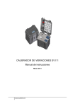
Vib@Work™
Calibration check of dosimeters measuring whole body vibrations.
Calibration check bench user manual
Version 1.1
TABLE OF CONTENTS
SECTION 1 - DESCRIPTION ....................................................................................................... 1
1.1 PRINCIPLE ................................................................................................................................ 1
1.2 PRACTICAL SEQUENCE ........................................................................................................... 1
1.3 CHECK BENCH COMPOSITION ................................................................................................. 2
SECTION 2 - INSTALLATION AND CONFIGURATION ......................................................... 3
2.1 CONTENT OF THE KIT............................................................................................................... 3
2.2 PREREQUISITES ....................................................................................................................... 3
2.3 INSTALLATION .......................................................................................................................... 3
2.3.1 INSTALLING THE WBCHECK SOFTWARE.............................................................................. 4
2.4 CONFIGURING THE WBCHECK SOFTWARE............................................................................ 4
2.4.1 MANAGING THE SENSORS .................................................................................................... 5
SECTION 3 - USE .......................................................................................................................... 8
3.1 PREREQUISITE CHECKS AND RECOMMENDATIONS................................................................ 8
3.2 LEVELLING OF THE BASE ........................................................................................................ 9
3.3 POSITIONING OF THE DEVICE TO BE CHECKED ON THE SENSOR FRAME ............................ 10
3.3.1 “SEAT” SENSOR................................................................................................................... 10
3.3.2 “FLOOR” SENSOR ................................................................................................................ 10
3.4 RUNNING THE CHECK SEQUENCE ......................................................................................... 11
3.4.1 CONNECTING THE SENSOR ................................................................................................ 11
3.4.2 THE 6 POSITION MEASUREMENTS ...................................................................................... 12
3.5 DISPLAYING THE RESULTS .................................................................................................... 15
SECTION 4 - UPDATING OF THE WBCHECK SOFTWARE .............................................. 17
SECTION 5 - SUPPORT ............................................................................................................. 18
i
Section 1 - Description
1.1 Principle
The check bench for “whole body” dosimeters allows the acceleration measurement of
“seat” or “floor” sensors to be validated along the 3 measurement axes X, Y and Z.
The sensor to be checked is placed into a mode that allows its acceleration due to the
Earth’s gravity (g = 9.81 m/s²) to be measured, which therefore serves as a reference.
Each measurement axis is successively positioned along the vertical (perpendicular to
the ground); the sensor measurement can then be compared to the acceleration of
gravity g.
In practice, two measurements are taken per axis: one in the positive direction, the other
in the negative direction. The difference between the two should provide a measurement
within the region of 2 g = 2 × 9.81m/s² = 19.62 m/s²
1.2 Practical sequence
The sequence is as follows:
1. The X axis of the sensor is aligned along the vertical in the positive direction
(Measurement X+ ≈ + g)
2. The X axis of the sensor is aligned along the vertical in the negative direction
(Measurement X- ≈ - g)
The difference between the 2 measurements X+ – X- should be 2 g
3. The Y axis of the sensor is aligned along the vertical in the positive direction
(Measurement Y+ ≈ + g)
4. The Y axis of the sensor is aligned along the vertical in the negative direction
(Measurement Y- ≈ - g)
The difference between the 2 measurements Y+ – Y- should be 2 g
5. The Z axis of the sensor is aligned along the vertical in the positive direction
(Measurement Z+ ≈ + g)
6. The Z axis of the sensor is aligned along the vertical in the negative direction
(Measurement Z- ≈ - g)
The difference between the 2 measurements Z+ – Z- should be 2 g
1
1.3 Check bench composition
The “whole body” dosimeter check bench is made up of the following 3 elements:
1. A levelling base for obtaining a level work surface.
2. A sensor frame on which the sensor is fixed and allowing it to be positioned along the
6 measurement directions (X+ , X- , Y+ , Y- , Z+ et Z- ).
3. Software (WBCheck) that provides guidance for positioning the sensor, collects the
measurements in the 6 measurement directions and displays the results of the check.
Figure 1: “Whole body” dosimeter check bench
2
Section 2 - Installation and Configuration
2.1 Content of the kit
The kit contains:
•
•
•
•
A levelling base made up of 2 spirit levels and 3 adjusting screws enabling horizontal
alignment.
A sensor frame to which a “seat” or “floor” sensor can be attached.
A CD-ROM containing the software and user manual
A quick installation guide
Figure 2: Kit
2.2 Prerequisites
Minimum configuration required for the PC:
• Windows XP® (Service Pack 2), Windows Vista® or Windows 7®
• Microsoft .NET Framework 3.5
• Hard disk drive with 20 Mb of available space
• CD-ROM reader
• VGA graphics card or compatible video graphics driver at up to 256K colours or
higher
• Keyboard
• Microsoft mouse or compatible pointing device
• Bluetooth communication device
2.3 Installation
•
•
•
Insert the CD-ROM supplied into your CD drive.
The installation programme begins automatically if this option is authorised on your
PC. If the installation programme doesn't start after a few seconds, display the CDROM contents and launch the "Start" programme.
Follow the on-screen instructions.
3
2.3.1 Installing the WBCheck software
•
•
Click on the "Installation of the WBCheck software" link; the WBCheck software
installs on your PC and starts up automatically.
The welcome screen is displayed (Figure 3)
Figure 3: Welcome screen
2.4 Configuring the WBCheck software
On the welcome screen, click on the "Next >" button. The screen below is displayed.
Figure 4: Sensor selection screen
The sensors that have already been configured are displayed in the list.
Updating the software via the Internet will not alter the list of already
configured sensors.
4
2.4.1 Managing the sensors
2.4.1.1 Adding a sensor
Prior to using your sensor, the data relating to it should be entered.
•
button. The sensor management window opens up (Figure 5). Here
Click on the
you will find a list of sensors that have been previously registered. If you are
configuring your first sensor, this list will be empty.
Figure 5: Managing the sensors
•
Click on the
button to add a sensor. A new window is displayed (Figure 6)
allowing you to enter the data relating to the sensor.
Figure 6: Adding a sensor
•
In the "Serial Number" field, enter your sensor's serial number (8 figures inscribed on
the sensor casing).
5
•
•
In the “software key” field, enter the key to allow the software to authorise the check of
the device.
In the “COM Port” field, enter the COM port number generated during the Bluetooth
pairing of the device (output COM port).
Figure 7: Adding a sensor (2)
•
The software keys allowing you to check the calibration of the sensors can be
obtained upon acquisition of a WBCheck licence. Please contact your
distributor to find out the terms and conditions of acquisition and use.
The software keys for WBCheck are different from the keys used for obtaining
vibration histories during ground measurements using your devices.
When the fields are completed, validate them by clicking on the
button. The
sensor selection window will then display the sensor that you have just entered.
6
Figure 8: Adding a sensor (3)
2.4.1.2 Deleting a sensor
•
•
Click on the
button to access the sensor management window, which displays the
list of sensors already registered.
Select a sensor in the list by clicking on the corresponding row.
•
Click on the
button to delete the selected sensor.
•
Click on the
button to close the sensor management window.
2.4.1.3 Editing a sensor
•
•
Click on the
button to access the sensor management window, which displays the
list of sensors already registered.
Select a sensor in the list by clicking on the corresponding row.
•
•
Click on the
button to access the data relating to the selected sensor.
Enter - for example - the sensor software key.
•
Click on the
button to close the sensor management window.
7
Section 3 - Use
This section explains how to implement the “whole body” sensor calibration check bench.
The various stages are listed below. The majority of the stages are performed using the
"WBCheck" software.
Stage 1 -
Prerequisite checks and recommendations
Stage 2 -
Levelling of the base
Stage 3 -
Positioning of the device to be checked (seat sensor or floor sensor)
on the check bench
Stage 4 -
Running of the check measurement sequence
Stage 5 -
Displaying the results
3.1 Prerequisite checks and recommendations
•
•
•
•
•
Make sure that the dosimeters to be checked are sufficiently charged.
Avoid checking devices in close proximity to strong hot or cold thermal sources.
Carry out the check on a stable surface and in a calm vibration-free environment.
The measurement sequence must be carried out in a single stage, with no
interruptions. If you wish to interrupt the sequence after 2 minutes have elapsed,
restart it from the beginning.
Due to its technological implementation, the Bluetooth communication becomes less
effective when 4 devices are activated within a radius of a few metres. This includes
the sensors, the PC used to run WBCheck, as well as other devices external to the
dosimeters (mobile telephones, earphones etc.). Check that there are not too many
Bluetooth devices activated within a confined area. If you are checking several
dosimeters, only remove one dosimeter at a time from its kit for each check. Keep all
of the others in their kits so that they remain switched off.
8
3.2 Levelling of the base
Position the levelling base on a stable
surface.
Check the level
Adjust the level along the first axis if
necessary
The bubble must be located between the 2
lines.
9
Adjust the level along the other axis if
necessary
The levelling base is now level.
3.3 Positioning of the device to be checked on the sensor frame
3.3.1 “Seat” sensor
Position the “seat” dosimeter in the area set aside for this purpose. Hold it in place using
the mounting bar.
Figure 9: Positioning of the “seat” dosimeter on the sensor frame
3.3.2 “Floor” sensor
Position the “floor” dosimeter in the area set aside for this purpose. Hold it in place using
the mounting bar.
10
Figure 10: Positioning of the “Floor” dosimeter on the sensor frame
There is a little room for manœuvre within the space to be occupied by the “floor”
sensor in order to take into account case machining tolerances.
Use the white threaded clamp on the mounting bar to wedge the sensor into
position.
3.4 Running the check sequence
3.4.1 Connecting the sensor
Launch the WBCheck software and display the sensor selection screen.
Figure 11: Sensor selection screen
From the list, select the sensor that you wish to check.
Click “next”.
11
The software then connects to the selected sensor via Bluetooth.
Figure 12: Connecting the sensor
Following connection, the 6-position measurement sequence commences.
The instructions are displayed under the heading of each window.
3.4.2 The 6 position measurements
Place the sensor frame in the X+ position and click “next”.
Figure 13: X+ position measurement
12
Return the sensor frame to the X- position and click “next”.
Figure 14: X- position measurement
Place the sensor frame in the Y+ position and click “next”.
Figure 15: Y+ position measurement
13
Return the sensor frame to the Y- position and click “next”.
Figure 16: Y- position measurement
Place the sensor frame in the Z+ position and click “next”.
Figure 17: Z+ position measurement
14
Return the sensor frame to the Z- position and click “next”.
Figure 18: Z- position measurement
3.5 Displaying the results
Following the measurement sequence along the 6 axis, the measurement results are
displayed. They are expressed as a percentage error per axis.
This percentage error must not exceed 4% (ISO8041 standard).
Figure 19: Results screen
15
You can then enter your name in the “Operator” field as well as a description of the check
in the “Comment” field.
Figure 20: Validation of the check
You can then save the data relating to the check that you have just carried out by clicking
on the
button. This is displayed in the “Previous test results” field.
Figure 21: Saving the calibration check data
By clicking on the
button, you can generate a report, print it and save it in various
formats (Excel and pdf).
16
Section 4 - Updating of the WBCheck software
Each time the WBCheck software is launched and as long as your PC is connected to the
internet, an available updates check is carried out.
If an update is available, a message is displayed prompting you to download it.
If for any reason you need to interrupt this update procedure, you can always download
the new version of the software manually by accessing the link http://www.vib-atwork.com/WBCheck/publish.htm.
Please use Microsoft Internet Explorer to log on to the update website
manually. The use of any other web browser may result in installation
problems.
17
Section 5 - Support
If you encounter any problems with the installation or use of this product, support can be
provided:
• Through your distributor (list on http://www.vib-at-work.com in the “distributors”
section).
• By visiting the http://www.vib-at-work.com web site
• By sending an e-mail to [email protected]
18
Manufactured by:
Micromega Dynamics SA
Parc Industriel de Noville-les-Bois
Rue du Trou du Sart, 10
B-5380 Fernelmont
Belgium
Tel. : +32 (0) 81 248 100
Fax: +32 (0) 81 248 101
Vib@Work is a registered trademark.


