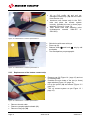
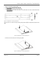
Download TOUCHPAD OCP5
Transcript
TOUCHPAD OCP5 150x60 / 190x90 / 200x60 / 240x90 FINA User’s Manual 2924.510.02 Version 2.3 Edition February 2011 Caution and safety precautions Never use any other charger than the supplied or a type approved by Swiss Timing. This could destroy the battery, cause damage to unit, and possible cause personal injury due to fire or/and electrical shock. Never bypass a power cord ground lead by breaking off the ground pin, or by using inappropriate extension cords or adapters. Never plug a power cord into the AC power source until you have made sure that all installation, cabling and power levels, are proper, and that the applicable procedures in this manual have been followed. Protect the equipment against splashing, rain and excessive sun rays. Never use the device if it is damaged or insecure. Verify the selection of the power distribution. Verify that the voltage quoted on the rating plate is the same as your voltage. Connect the appliance only to power sockets with protective earth. The use of incorrect connection voids warranty. This program may be modified at any time without prior notification. Do not open the case; there is nothing that needs servicing inside it. Nevertheless, if the case must be opened, you must call for some qualified personnel. The power supply cable must be disconnected before opening the case. During the transport of all Swiss Timing equipment delivered with a reusable carry case, the said case should be used at all times. This is imperative to limit the damage, such as shocks or vibration that can be caused to the units during transport. The same cases should also be used when returning equipment to Swiss Timing for repair. Swiss Timing reserves the right to refuse all guarantees if this condition is not fulfilled. If the installation includes a horn, be sure to maintain a sufficient security distance from the public. Documentation Updates Swiss Timing Ltd. reserves the right to make improvements in the products described in this documentation at any time without prior notice. Furthermore, Swiss Timing Ltd. reserves the right to revise this documentation in its content at any time and without any obligation to notify any person or organization of such revision. Disclaimer The information provided in this documentation has been obtained from sources believed to be reliable, accurate and current. However, Swiss Timing Ltd. makes no representation or warranty, express or implied, with respect, but not limited to, the completeness, accuracy, correctness and actuality of the content of this documentation. Swiss Timing Ltd. specifically disclaims any implied warranty of merchantability, quality and/or fitness for any particular purpose. Swiss Timing Ltd. shall not be liable for errors contained in this documentation or for incidental or consequential damages in connection with the supply, performance or use of this documentation. Environment This symbol indicates that this product should not be disposed with household waste. It has to be returned to a local authorized collection system. By following this procedure you will contribute to the protection of the environment and human health. The recycling of the materials will help to conserve natural resources. Copyright © Swiss Timing Ltd. All rights reserved. This documentation may not, as a whole or in part, be copied, translated, reproduced, transmitted or reduced and/or stored to any electronic medium or machine-readable form without the prior written consent of Swiss Timing Ltd. 150x60 / 190x90 / 200x60 / 240x90 FINA / TOUCHPAD OCP5 TABLE OF CONTENTS 1 INTRODUCTION........................................................................................................... 1 2 DESCRIPTION OF THE OCP5 TOUCHPAD ............................................................... 2 3 MOUNTING THE OCP5 TOUCHPAD .......................................................................... 3 4 3.1 Suspension of gutter wall (60cm Touchpad) .................................................................. 3 3.2 Fixing with angle brackets (90cm Touchpad) ................................................................. 3 3.3 Fixing without angle brackets (90cm Touchpad) ............................................................ 3 HANDLING THE OCP5 TOUCHPAD ........................................................................... 8 4.1 5 4.1.1 Check without pressure applied ...................................................................... 8 4.1.2 Sensitivity test with pressure applied ............................................................... 9 4.1.3 Operational test with timing installation ......................................................... 10 MAINTENANCE ......................................................................................................... 11 5.1 5.2 6 Test, preparation and timing ........................................................................................... 8 Handling ....................................................................................................................... 11 5.1.1 Drying ............................................................................................................ 11 5.1.2 Storage .......................................................................................................... 11 5.1.3 Cleaning of the contact system ..................................................................... 12 Repair ........................................................................................................................... 12 5.2.1 Test before repair work .................................................................................. 12 5.2.2 Replacement of the top contact strip ............................................................. 13 5.2.3 Replacement of the bottom contact strip ....................................................... 14 5.2.4 Replacement of a PVC profile (4) .................................................................. 16 5.2.5 Stick contact strips ......................................................................................... 17 APPENDIX .................................................................................................................. 18 6.1 Index of tables and figures ........................................................................................... 19 6.2 Abbreviations and symbols........................................................................................... 20 6.3 Version history .............................................................................................................. 20 SWISS TIMING LTD P.O. Box 138, rue de l'Envers 1 2606 Corgémont, Switzerland www.swisstiming.com Phone +41 32 488 36 11 Fax +41 32 488 36 09 [email protected] 150x60 / 190x90 / 200x60 / 240x90 FINA / TOUCHPAD OCP5 1 INTRODUCTION The touchpad OCP5 (see chapter 6 APPENDIX) is composed of a number of narrow PVC profiles (4), the edges of which slide into each other and which are enclosed by a stainless steel frame (5). On the rear of the touchpad, two or three tape switches (12) are sandwiched between the PVC profiles (types 190x90 and 240x90) (4) or steel channels (10) and (14). Any pressure applied by a swimmer reaching the arrival wall causes the closure of tape switch contacts which is instantaneously recorded by the timing system. Version 2.3 2924.510.02 Page 1 2 DESCRIPTION OF THE OCP5 TOUCHPAD Pos. Description 150x60 2924.000 (2) (3) (4) (8) (9) (11) (12) (13) (14) (18) (23) (24) (25) (26) (19) (20) (21) (22) (E) (G) Cap Cable Yellow PVC slat Black PVC slat Yellow/black PVC slat Yellow PVC slats with black "OMEGA" inscription (Set of 12 slats) Black PVC ribbon Snap-in-fastener Upper plastic sheath - 235cm Contact strip Protection envelope 51mm 2924.155 2924.157 2924.663 2924.051 (Length to be announced) Tape switch guiding channel Angle brackets Buzzer Dynamometer Perforated contact strip holder 38mm (Length to be announced) Fixing clip 6x45 mm peg Con. M4x30 mm screw Nylon washer M4 6 mm rock-drill Complete fixing angle brackets Special nut Maintenance material 2924.039 Article number 190x90 200x60 2924.005 2924.001 240x90 2924.003 FINA 9039.8517 2924.667 2924.154 2924.155 2924.156 2924.157 2924.158 2924.154 2924.156 2924.158 2924.639 2924.639 2924.60 2924.661 9039.8110 2924.108 2924.086 2924.086 2924.647 2924.071 2924.071 2924.088 2924.059 2924.076 2924.631 2924.632 2924.065 2924.076 2924.068 2924.153 2924.626 2924.098 2924.621 2924.161 9039.8580 9513.1589 9597.4001 9051.9804 2924.626 2924.098 2924.622 2924.621 9039.8580 9513.1589 9597.4001 9051.9804 2924.622 See APPENDIX (page 18) Page 2 2924.510.02 Version 2.3 150x60 / 190x90 / 200x60 / 240x90 FINA / TOUCHPAD OCP5 3 MOUNTING THE OCP5 TOUCHPAD 3.1 Suspension of gutter wall (60cm Touchpad) Adjust angle brackets (E) according to thickness of gutter wall and tighten special nut (G). Figure 1 - Touchpad 60cm / Gutter mounting 3.2 Fixing with angle brackets (90cm Touchpad) Install angle brackets (18) and pull them so that the touchpad lies flat against the wall of the pool. Holes dimensions: Ø6mm x 45mm See pages 4 and 5. Figure 2 - Touchpad 90cm / Mounting 3.3 Fixing without angle brackets (90cm Touchpad) The touchpad must be screwed on so that the touchpad lies flat against the wall of the pool. Holes dimensions: Ø6mm x 45mm See pages 6 and 7. Version 2.3 2924.510.02 Page 3 ANGLE BRACKET MOUNTING Touchpad 240x90 Figure 3 - Touchpad 240x90 / Angle bracket mounting Page 4 2924.510.02 Version 2.3 150x60 / 190x90 / 200x60 / 240x90 FINA / TOUCHPAD OCP5 DIRECT MOUNTING Touchpad 240x90 Figure 4 - Touchpad 240x90 / Direct mounting Version 2.3 2924.510.02 Page 5 ANGLE BRACKET MOUNTING Touchpad 190x90 Figure 5 - Touchpad 190x90 / Angle bracket mounting Page 6 2924.510.02 Version 2.3 150x60 / 190x90 / 200x60 / 240x90 FINA / TOUCHPAD OCP5 DIRECT MOUNTING Touchpad 190x90 Figure 6 - Touchpad 190x90 / Direct mounting Version 2.3 2924.510.02 Page 7 4 HANDLING THE OCP5 TOUCHPAD 4.1 Test, preparation and timing 60cm Figure 7 - Touchpad 60cm / Test Figure 8 - Touchpad 90cm / Test 4.1.1 Check without pressure applied Connect the buzzer (23) to cable (3). The buzzer should produce no sound if no pressure is applied upon the touchpad. A continuous sounding of the buzzer can have one of the following causes: Page 8 Compression of a contact strip due to a convex pool wall. Tape switch guiding channel (14) or contact strip (12) bent. Top angle bar (10) bent. Foreign body between PVC profile (4) and contact strip assembly (10) (12) or (14) (12). PVC profiles (4) disjoined. If an external cause cannot be found, repair the touchpad as explained in section 5.2. 2924.510.02 Version 2.3 150x60 / 190x90 / 200x60 / 240x90 FINA / TOUCHPAD OCP5 4.1.2 Sensitivity test with pressure applied Connect buzzer (23) to cable (3) as per 4.1. Measure the power required to produce a buzzing sound when applying pressure with the dynamometer (24) at water level and underneath (the dynamometer must be placed in the middle of a profile (4)). Sensibility range: 1,5 to 3,5 kp. There can be different reasons for the insensibility of a touchpad: The contact strip does not make any contact because its electric cable is broken or the (3) soldered joint is damaged. The contact strip (12) or the tape switch guiding channel (14) or the top angle bar (10) is bent. The contact strip is internal damaged. Roughness between two contact strips (12) and the PVC profile (4) cannot close the contact(s) anymore. Limited Movement In this case: Remove roughness… Or move the touchpad horizontally or vertically (if possible). Figure 9 - Contact / Sensibility If you cannot find any external causes, repair touchpad as per paragraph 5.2. Version 2.3 2924.510.02 Page 9 
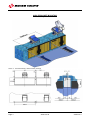
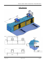
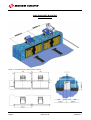
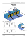
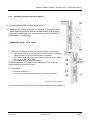
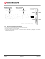
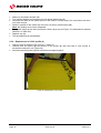
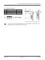
Standard mounting Large rib Small rib Special mounting Small rib Large rib Large rib Note: it is possible to reduce the sensitivity of the touchpad through a special mounting of the contact strips. Nevertheless we recommend the standard mounting. The sensitivity can be reduced per zone, if only one contact strip is placed with the special mounting. Small rib Standard mounting Large rib Small rib Figure 10 - Contact / Standard mounting 4.1.3 Operational test with timing installation Connect the touchpad with cable (3) to the timing installation. Simulate arrivals by touching the pads. If the timing devices do not receive any impulses, follow instruction in paragraph 5.2 or user's manual of timing devices. Page 10 2924.510.02 Version 2.3 150x60 / 190x90 / 200x60 / 240x90 FINA / TOUCHPAD OCP5 5 MAINTENANCE 5.1 5.1.1 Handling Drying Take the touchpad out of the water. Rinse with clean water. Put it into a standing position and allow to trickle off as per Figure 11. Wipe with a cloth. Do not leave the touchpads unused in the water. The drying time must be longer than the time in the water, so that the absorbed water can trickle off. 5.1.2 Storage Provide an arrangement to store the touchpads or get in contact with Swiss Timing Ltd to order a red trolley (Article No. 2924.903). Trolley should be stored in a dry room and be protected from dust. Figure 11 - Touchpads on trolley ABSOLUTELY AVOID STORING THE PADS HORIZONTALLY AND ONE ON TOP OF EACH OTHER. THIS FAULTY STORAGE COULD DAMAGE THE CONTACT STRIPS. Version 2.3 2924.510.02 Page 11 5.1.3 Cleaning of the contact system Figure 12 - Maintenance / Contact cleaning I Figure 13 - Maintenance / Contact cleaning I Pull the ends of bottom switch assembly (14) out of connection angles by lifting up and turn upside down. 5.2 Remove plastic sheath (13) and the transparent polyester brace (25). Clean the dirty parts (sensitivity loss). Change the elements if they are ripped up or too hard. Repair 5.2.1 Test before repair work See also paragraph 4. Test the doubtful profile on another swim lane and control with the timing installation. It is possible that the coder or the cable is defect and not the touchpad. Does the test above confirm the damage o the touchpad, change the contact strip as follows: Figure 14 - Maintenance / Contact test I Figure 15 - Maintenance / Contact test II Remove cap (2) and cut isolating tube. Page 12 2924.510.02 Unsolder the wire leads of the two (or three) tape switches. Find the defective tape switch by means of the buzzer (23). Version 2.3 150x60 / 190x90 / 200x60 / 240x90 FINA / TOUCHPAD OCP5 Electronic measurement: Closed contact If the resistance is higher than 50, the contact strip must be changed, because the electrodes are oxidized. Open contact If the resistance is in the range of 100 k, the contact strip must be possibly changed, because an important amount of water could have penetrated, this can produce dirtiness between the contacts. 5.2.2 Replacement of the top contact strip Remove cap (2) (Figure 14 / page 12) and cut up isolating tube. Unsolder the wire leads of the two (or three) tape switches (Figure 15 / page 12). Lift up hook and hook only by old touchpads, to remove the black PVC profile (4). Figure 16 - Maintenance / Contact replacement I Remove snap-in fasteners (9) from cover, a length of 60cm. Figure 17 - Maintenance / Contact replacement II Version 2.3 2924.510.02 Page 13 Lift up PVC profile (4) and pull out damaged contact strip (12) with the cable from the tube (11). Introduce new contact strip in the PVC tube and place the contact system correctly. Unsolder the two (or three) tape switches (Figure 16 / page 13). Pass shrink tube over soldering point (maintenance material 2924.621 or 2924.622). Figure 18 - Maintenance / Contact replacement III Shrink tube with warm air dryer. Place cap (2). Redress hook and hook only by old touchpads. Test touchpad as per paragraph 4. Figure 19 - Maintenance / Contact replacement IV 5.2.3 Replacement of the bottom contact strip Remove cap (2) (Figure 14 / page 12) and cut up isolating tube. Unsolder the wire leads of the two (or three) tape switches (Figure 15 / page 12). Lift up the profile (14) and extract (Figure 12 / page 12). Turn up contact system as per Figure 13 / page 12). Figure 20 - Maintenance - Contact replacement V Remove electric cable. Remove complete plastic sheath (13). Remove fixing clip (26). Page 14 2924.510.02 Version 2.3 150x60 / 190x90 / 200x60 / 240x90 FINA / TOUCHPAD OCP5 Remove transparent polyester (25). Take out contact strip (12) as per Figure 20. Old touchpad: unstuck contact strip (12). Insert new contact strip (12) on the profile (14). Old touchpad: stick contact strip (12) on the profile (14). Use fresh, double-sided sticker (paragraph 5.2.5). Figure 21 - Maintenance / Contact replacement VI Introduce first on one side of the tape switch guiding channel (25) the transparent polyester brace (14) … Figure 22 - Maintenance / Contact replacement VII … and then also on the other side. Set fixing clips (26). Figure 23 - Maintenance / Contact replacement VIII Version 2.3 2924.510.02 Page 15 Slide over the plastic sheath (13). Turn contact system and introduce it in the lateral guide bars (6). Introduce the cable on the lateral profile of the reserve contact strip in the connection duct then cut it and uncover. Solder in parallel to the cables (3) of the two (or three) contact strips (12). Note: the polarity must not be respected. Extract the tube from the duct and shrink it with a dryer as per Figure 19 (maintenance material 2924.621 or 2924.622). Replace cap (2). Test touchpad as per paragraph 4. 5.2.4 Replacement of a PVC profile (4) Remove snap-in fasteners (9) (Figure 17/ page 13). Unhook from the frame (5) the bottom of the profile (4) with the help of your thumb or screwdriver and pull it out (Figure 24). Introduce the new profile (4) and rebuild the touchpad together. Figure 24 - Maintenance / PVC profile Page 16 2924.510.02 Version 2.3 150x60 / 190x90 / 200x60 / 240x90 FINA / TOUCHPAD OCP5 5.2.5 Stick contact strips Pos. (a) (b) (c) (d)* Type 3M 4930 3M 4930 3M 927 3M927 (d)* 9x0.6mm 19x0.6mm 0.1mm 0.1mm Article No. 9038.3553 9038.3556 9038.3520 9038.3520 Old touchpad Only stick, if the contact strip is mounted without the transparent polyester (25) Figure 25 - Maintenance / Double-sided sticker Note: in process of time, the double-sided sticker could be modified. If the 3M 4930 is not employed anymore, use 3M 4945 (attention: thicker). Version 2.3 2924.510.02 Page 17 6 APPENDIX Page 18 2924.510.02 Version 2.3 150x60 / 190x90 / 200x60 / 240x90 FINA / TOUCHPAD OCP5 6.1 Index of tables and figures Index of tables Index of figures Figure 1 - Touchpad 60cm / Gutter mounting ................................................................................... 3 Figure 2 - Touchpad 90cm / Mounting .............................................................................................. 3 Figure 3 - Touchpad 240x90 / Angle bracket mounting .................................................................... 4 Figure 4 - Touchpad 240x90 / Direct mounting ................................................................................. 5 Figure 5 - Touchpad 190x90 / Angle bracket mounting .................................................................... 6 Figure 6 - Touchpad 190x90 / Direct mounting ................................................................................. 7 Figure 7 - Touchpad 60cm / Test ...................................................................................................... 8 Figure 8 - Touchpad 90cm / Test ...................................................................................................... 8 Figure 9 - Contact / Sensibility .......................................................................................................... 9 Figure 10 - Contact / Standard mounting ........................................................................................ 10 Figure 11 - Touchpads on trolley .................................................................................................... 11 Figure 12 - Maintenance / Contact cleaning I ................................................................................. 12 Figure 13 - Maintenance / Contact cleaning I ................................................................................. 12 Figure 14 - Maintenance / Contact test I ......................................................................................... 12 Figure 15 - Maintenance / Contact test II ........................................................................................ 12 Figure 16 - Maintenance / Contact replacement I ........................................................................... 13 Figure 17 - Maintenance / Contact replacement II .......................................................................... 13 Figure 18 - Maintenance / Contact replacement III ......................................................................... 14 Figure 19 - Maintenance / Contact replacement IV ........................................................................ 14 Figure 20 - Maintenance - Contact replacement V ......................................................................... 14 Figure 21 - Maintenance / Contact replacement VI ........................................................................ 15 Figure 22 - Maintenance / Contact replacement VII ....................................................................... 15 Figure 23 - Maintenance / Contact replacement VIII ...................................................................... 15 Figure 24 - Maintenance / PVC profile ............................................................................................ 16 Figure 25 - Maintenance / Double-sided sticker ............................................................................. 17 Version 2.3 2924.510.02 Page 19 6.2 Abbreviations and symbols Abbreviations Symbols Syntax for buttons, labels, menu items etc. in the applications Keys, Buttons and labels [key], [OK], [Result] Menu items "Menu1" > "Menu2" > … Tabs <Tab name> Switches ("switch" box) ‘Active’ Program and error messages "Connection succeeded" Files test.bmp Folder structure Folder1 / Folder2 / … 6.3 Version history Version Date Modifications since last version 1.0 01/01/10 Initial version 2.3 02/02/11 Drawings and various modifications Page 20 2924.510.02 Version 2.3 150x60 / 190x90 / 200x60 / 240x90 FINA / TOUCHPAD OCP5 NOTES Version 2.3 2924.510.02 Page 21 SWISS TIMING LTD P.O. Box 138, rue de l'Envers 1 2606 Corgémont, Switzerland www.swisstiming.com Phone +41 32 488 36 11 Fax +41 32 488 36 09 [email protected]