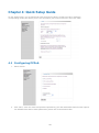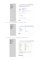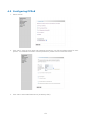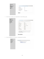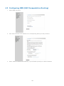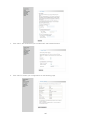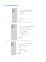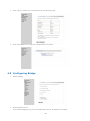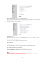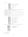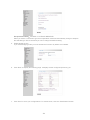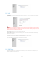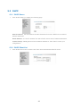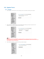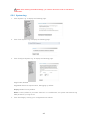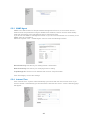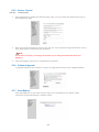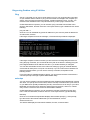
1
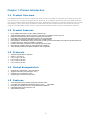
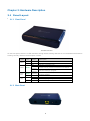
ADSL2/2+ Router 8012-B1 User’s Manual Version 1.0 Last Revised: 11-07-11 User Manual Innoband 8012-B1 Information in this document is subject to change without notice and does not represent a commitment on the part of Innoband Technologies, Inc. The software described in this document is furnished under a license agreement and may be used or copied only in accordance with the terms of the license agreement. It is against the law to copy the software on any other medium except as specifically allowed in the license agreement. The licensee may make one copy of the software for backup purposes. No part of this manual may be reproduced or transmitted in any form or by any means, electronic or mechanical, including photocopying and recording, for any purpose without the written permission of Innoband Technologies, Inc. All contents are Copyright © 2011 Innoband, Inc. All rights reserved. Manual Version 1.0 Nov 2011 Innoband is a trademark of Innoband Technologies, Inc. The trademarks, logos and service marks (―Marks‖) displayed on this manual are the property of Innoband or other third parties. Users are not permitted to use these Marks without the prior written consent of Innoband or such third party that may own the Mark. IBM is a registered trademark of International Business Machines Corporation. Intel and Pentium are registered trademarks of Intel Corporation. Microsoft, MS-DOS, Windows, and the Windows logo are registered trademarks of Microsoft Corporation. All other products are trademarks or registered trademarks of their respective owners. Version 1.0 Last Revised: 11-07-11 Table of Contents ADSL2/2+ Router ..................................................................................................... 1 8012-B1 ................................................................................................................. 1 User‘s Manual .......................................................................................................... 1 Chapter 1: Product Introduction ..................................................................................... 3 1.1 Product Overview.................................................................................................... 3 1.2 Product Features..................................................................................................... 3 1.3 Protocols ............................................................................................................... 3 1.4 Packet Encapsulation ............................................................................................... 3 1.5 Features ................................................................................................................ 3 Chapter 2: Hardware Description ................................................................................... 4 2.1 Panel Layout .......................................................................................................... 4 2.1.1 Front Panel ...................................................................................................... 4 2.1.2 Back Panel ....................................................................................................... 4 2.1.3 8012-B1’s Back Panel ........................................................................................ 5 2.2 Installation Environment .......................................................................................... 5 2.2.1 Physical Environment Requirement ..................................................................... 5 2.2.2 Recommended Working Environment .................................................................. 5 2.3 Hardware Installation .............................................................................................. 5 2.3.1 Installation Requirement.................................................................................... 5 2.4 Installation Procedures ............................................................................................ 5 Chapter 3: Login to Web Management Interface ................................................................. 7 3.1 Configuring PC ....................................................................................................... 7 3.2 Verifying Connection ............................................................................................... 8 3.3 Login to Router ....................................................................................................... 9 Chapter 4: Quick Setup Guide .................................................................................... 10 4.1 Configuring PPPoA ................................................................................................ 10 4.2 Configuring PPPoE ................................................................................................. 13 4.3 Configuring MER (MAC Encapsulation Routing) ......................................................... 15 4.4 Configuring IPoA ................................................................................................... 18 4.5 Configuring Bridge ................................................................................................ 19 Chapter 5: Configuration Guide ................................................................................... 21 5.1 Status ................................................................................................................. 21 5.2 Advanced Setting .................................................................................................. 22 5.2.1 WAN ............................................................................................................. 22 5.2.2 LAN .............................................................................................................. 32 5.2.3 IGMP Proxy .................................................................................................... 32 5.2.4 NAT .............................................................................................................. 33 5.2.5 Security......................................................................................................... 36 5.2.6 Routing ......................................................................................................... 38 5.2.7 DNS .............................................................................................................. 40 5.2.8 DSL .............................................................................................................. 41 5.3 DHCP .................................................................................................................. 42 5.3.1 DHCP Server .................................................................................................. 42 5.3.2 DHCP Client List ............................................................................................. 42 5.4 Diagnostic............................................................................................................ 43 5.5 System Tools ....................................................................................................... 44 5.5.1 Settings......................................................................................................... 44 5.5.2 System Log .................................................................................................... 45 5.5.3 SNMP Agent ................................................................................................... 46 5.5.4 Internet Time ................................................................................................. 46 5.5.5 Access Control ................................................................................................ 47 5.5.6 Software Upgrade ........................................................................................... 47 5.5.7 Save/Reboot .................................................................................................. 47 A Appendix A - Configuring the Internet Settings .................................................. 48 Configuring Ethernet PCs .................................................................................................... 48 Before you begin ......................................................................................................... 48 Windows® XP PCs ....................................................................................................... 48 1 Windows 2000 PCs ...................................................................................................... Windows Me PCs ......................................................................................................... Assigning static Internet information to your PCs ............................................................. B Appendix B - Troubleshooting .......................................................................... 51 Troubleshooting Suggestions ................................................................................................ Diagnosing Problem using IP Utilities ...................................................................................... Ping ........................................................................................................................... nslookup .................................................................................................................... C Appendix C - Glossary ..................................................................................... 55 D Appendix D - Specification ............................................................................... 63 E Appendix E – Warranty ................................................................................... 65 F Appendix F - Regulation .................................................................................. 67 G Appendix G - Contact information ..................................................................... 69 2 48 49 49 51 53 53 53 Chapter 1: Product Introduction 1.1 Product Overview Our INNOBAND 8012-B1 which complies with ADSL, ADSL2 and ADSL2+ standards is an ADSL terminal with one Ethernet port. It supports multiple network protocols, up to 24Mbps downstream rate and 1Mbps upstream rate, as well as NAT Routing and Bridging functions. With stable performance, exquisite appearance and s great compatibility, it is the best choice for SOHO, small enterprise and individual users to access the Internet. By using the provided setup wizard, users can achieve fast installation without entering management interface. 1.2 Product Features Up to 24Mbps downstream rate and 1Mbps upstream rate Supports Bridge, PPPoE, PPPoA, Dynamic IP and Static IP broadband access ways, etc 6000V enhanced lightning-proof design for lightning-intensive areas Compatible with mainstream DSLAM equipments, strong adaptability Wide voltage range design adaptable to areas with unstable voltage FDM adopted to enable calling, faxing and Internet accessing to proceed simultaneously without mutual interferences Complies with ADSL, ADSL2 and ADSL2+ standards Provides Web-based management and supports firmware upgrade Strong driving capability with up to 6.5Km transmission distance Setup Wizard provided for simplified installation and configuration 1.3 Protocols Supports full-rate ADSL2+ standard ANSI T1. 413 Issue 2 ITU-T G. 992. 1 (G. dmt) ITU-T G. 992. 2 (G. dmt) ITU-T G. 992. 3 (G. dmt) ITU-T G. 992. 5 (G. dmt) 1.4 Packet Encapsulation Supports RFC 1483 Bridge、RFC 1483 Router Supports Classical IP over ATM (RFC 1577) Supports ppp over ATM (RFC 2346) Supports ppp over Ethernet (RFC 2516) 1.5 Features enhanced lightning-proof design for lightning-intensive areas Compatible with mainstream DSLAM equipment, strong adaptability Strong driving capability with up to 6.5Km transmission distance Integrated Modem and Router all-in-one Setup Wizard provided 3 Chapter 2: Hardware Description 2.1 Panel Layout 2.1.1 Front Panel 8012-B1‘s Front Panel On the front panel, there are 4 LED indicators through whose working statuses we can tell whether the Router is working correctly. Below is the description of them. LEDs Color Status Description PWR Green — Device is on Power is off DSL line connection is up ADSL Green ON OFF ON Slow Flashing Fast Flashing PPP/ ACT Green Flashing — Green OFF ON Flashing OFF LAN — Router has not yet been connected to CO devices DSL line training in progress Router‘s telephone line port is transmitting and receiving packets No data traffic over WAN connection Ethernet interface is ready to work User data going through Ethernet port No Ethernet signal is detected 2.1.2 Back Panel 4 2.1.3 8012-B1’s Back Panel ON/OFF:Power button turning on/off the Router‘s power PWR:the power socket for power adapter. Notice: please use the matched power adapter (DC9V600mA). Use of a different adapter may damage your Router. Reset Button:The reset button for restoring to factory default settings Caution: do NOT press Reset button unless you want to have current configurations deleted. To reboot the Router and restore factory default settings, Press and hold the button for 3 seconds with something pointed. LAN: RJ-45 LAN port for connecting to hub, switch or PC‘s network adapter in your local network. LINE: Used to connect to the Modem port of Voice Splitter. 2.2 Installation Environment 2.2.1 Physical Environment Requirement Install the device horizontally Do not wipe the device with wet cloth Keep the device far away from hot objects Keep the environment clean and dry Power off the device and unplug the power adapter in lighting storm weather 2.2.2 Recommended Working Environment Temperature: 0˚C ~ 40۫ C Humidity: 10%~90% RH non-condensing 2.3 Hardware Installation 2.3.1 Installation Requirement Before installing the device, make sure the following requirements are met. 1. Have enabled ADSL service and acquired at least one WAN IP address or user name and password provided by your ISP 2. One or more PCs with 10Base-T/100Base-T Network Adapter(s) 3. PC supporting Internet Explorer browser 6.0 or above 2.4 Installation Procedures Connect the Voice Splitter‘s Modem port to 8012-B1Router‘s LINE port with telephone line (RJ11) and ―Phone‖ port to a telephone. Insert a telephone line to the splitter‘s ―Line‖ port. Connect one end of a network cable to 8012-B1‘ LAN (RJ45) port and the other end to PC‘s NIC. Plug the included power adapter into the Power socket on 8012-B1 Router and turn on the power switch. Check all connections as shown in the below figure to see if everything is ready. 8012-B1 Hardware Installation 5 Tip: To protect the device against thunderbolt attack, disconnect power adapter and telephone line connection. 6 Chapter 3: Login to Web Management Interface 3.1 Configuring PC 1. Right click ―My Network Places‖ on the desktop and select ―Properties‖. 2. Right click ―Local Area Connection‖ in the appearing window and select ―Properties‖. 3. Select ―Internet Protocol (TCP/IP)‖ and click ―Properties‖. 4. Select ―Obtain an IP address automatically‖ or ―Use the following IP address‖. a. ―Obtain an IP address automatically‖ is shown in the figure below: 7 b. ―Use the Following IP Address‖ is shown in the figure below: IP address: 192.168.1.XXX:(XXX is any number from 2~254) Subnet Mask: 255.255.255.0 Gateway: 192.168.1.1 DNS server: Enter your local DNS server address (consult your ISP if necessary). Or use the router as the DNS proxy server. Then click ―OK‖ to submit and save the configurations. 3.2 Verifying Connection 1. Select ―Start‖→All Programs‖→―Accessories‖→―Command Prompt‖. 2. Input ―ping 192.168.1.1‖ and press ―Enter‖. If the screen displays as shown in below figure, it means your PC is connected to your router successfully. 8 3.3 Login to Router 1. To access the router‘s Web-based interface, launch a web browser such as Internet Explorer and enter the Router‘s default IP address, http://192.168.1.1 and press ―Enter‖. 2. Input ―admin‖ as both the ―User Name‖ and ―Password‖ and then click ―OK‖ (Both user name and password are admin by default) . 3. If you entered the correct user name and password, you will see the Page below. 9 Chapter 4: Quick Setup Guide On the ―wizard‖ page, you are required to enter VPI and VCI values. Consult your ISP or select the corresponding country and area if you are not clear about your local VCI and VPI. Then click ―Next‖. 4.1 Configuring PPPoA 1. Select PPPoA 2. Click ―Next‖, enter user name and password provided by your ISP and default values for other options. For detailed information of these parameters, please refer to introductions later. 10 3. Click ―Next‘‘ and enable WAN service (enabled by default). 4. Click ―Next‖ to review your configurations on the following page. 11 5. Click ―Save/Reboot‖ to bring your configurations into effects. 12 4.2 Configuring PPPoE 1. Select PPPoE 2. Click ―Next‖, enter the user name and password provided by your ISP and default values for other options. For detailed information of these parameters, please refer to introductions later. 3. Click ―Next‘‘ and enable WAN service (enabled by fault). 13 4. Click ―Next‖ to review your configurations on the following page. 5. Click ―Save/Reboot‖ to bring your configurations into effects. 14 4.3 Configuring MER (MAC Encapsulation Routing) 1. Select MER connection 2. Click ―Next‖ and enter an IP address in the corresponding field if your ISP provided it. 3. Select ―Obtain IP Address Automatically‖ if your ISP didn‘t provide you a static IP address. 15 4. Click ―Next‖. We recommend you to enable NAT and firewall functions. 5. Click ―Next‖ to review your configurations on the following page. 16 6. Click ―Save/Reboot‖ to bring your configurations into effects. 17 4.4 Configuring IPoA 1. Select IPoA 2. Click ―Next‖ and enter an IP address and a subnet mask provided by your ISP. 3. Click ―Next‖. We recommend you to enable NAT and firewall functions. 18 4. Click ―Next‖ to review your configurations on the following page. 5. Click ―Save/Reboot‖ to bring your configurations into effects. 4.5 Configuring Bridge 1. Select bridging 2. Enable bridge service If you select bridging mode you must enable this function. By default it is enabled. 19 3. Click ―Next‖ to display the following page. It displays all the configured options by you. Click ―Save‖ to save your configurations. To activate them, click the ―Save/Reboot‖ button 20 Chapter 5: Configuration Guide 5.1 Status 1. Click ―Running Status‖---―Summary‖ to display ―Device Info‖ and ―DSL‖ information. Note: Default Gateway:Default gateway is not displayed in complete bridge mode, while in other modes (like PPPoE / PPPoA) it displays the IP address of an uplink device. Primary/ Secondary DNS Address: DNS address is obtained from an uplink device in PPPoA / PPPoE mode while it is not displayed in complete bridge mode. 2. Click ―WAN‖ to view the following page which displays parameters about WAN connection 3. Click ―Route‖ to view router‘s routing table. 21 5.2 Advanced Setting 5.2.1 WAN Click ―WAN‖ to add/modify WAN information. Note: You need to reboot the router to bring new configurations into effects after you modify or add new information. VPI (Virtual Path Identifier):the virtual path between two points in ATM network. Its valid value is any number from 0 to 255 VCI (Virtual Channel Identifier):the virtual channel between two points in ATM network. Its valid value is any number from 32 to 65535(1—31is reserved for common protocols) Service Type: for selecting one service type, usually the default value. Enable QoS: for enabling or disabling QoS. 5.2.1.2 PPPoA mode 1. Select PPPoA 22 Encapsulation Mode:VC/MUX / LLC/ENCAPSULATION When you select a connection mode the encapsulation mode will automatically change to adapt to the selected mode. We recommend you not to change the default setting. 2. Click ―Next‖ to display the following page. 1)Authentication Method: Auto/PAP/CHAP/MSCHAP. Auto is the commonly selected one. 2)Dialup on Demand: When enabled, the device will automatically cut the connection with ISP if it has not detected connection request within a configured time. 3)PPP IP Extension: The IP address obtained through upstream link will be assigned to the PC connected to the router when router is only connected to one PC. 4)Use Static IP: The router will use this IP as a WAN IP instead of dynamically obtaining one through upstream link after you have enabled this option. 5)Retry PPP Password on Authentication Error 3. Click ―Next‖ to display the following page. 23 Enable IGMP Multicast: IGMP agent. For example, check this option when you want to enable the IPTV in the PPPoE mode. Enable WAN Service: enabled by default. It is recommended not to disable it, unless you do not need to activate your WAN. 4. Click ―Next‖ to display the following page. 6. It displays all configured options by you. 5. Click ―Save‖ to save your configurations. To activate them, click the ―Save/Reboot‖ button. 5.2.1.3 PPPoE mode 1. Select PPPoE 24 Encapsulation Mode: VC/MUX or LLC/SNAP-BRIDGING When you select a connection type the encapsulation mode will automatically change to adapt to the selected type. We recommend you not to change the default setting. 2. Click ―Next‖ to display the following page. 1)Authentication Method:Auto/PAP/CHAP/MSCHAP. Auto is the commonly selected one. 2)Dialup on Demand: When enabled, the device will automatically cut the connection with ISP if it has not detected connection request within a configured time. 3)PPP IP Extension: The IP address obtained through upstream link will be directly assigned to the PC connected to the router when router is only connected to one PC. 4)Use Static IP: The router will use this IP as a WAN IP instead of dynamically obtaining one through upstream link after you have enabled this option. 5)Retry PPP Password on Authentication Error 3. Click ―Next‖ to display the following page. 25 Enable IGMP Multicast: IGMP agent. For example, check this option when you want to enable the IPTV in the PPPoE mode. Enable WAN Service: enabled by default. It is recommended not to disable it, unless you do not need to activate your WAN. 4. Click ―Next‖ to display the following page. 6. It displays all configured options by you. 5. Click ―Save‖ to save your configurations. To activate them, click the ―Save/Reboot‖ button. 5.2.1.4 MER mode 1. Select MER 26 Encapsulation Mode:VC/MUX or LLC/SNAP-BRIDGING When you select a connection type the encapsulation mode will automatically change to adapt to the selected type. We recommend you not to change the default setting. 2. Click ―Next‖ to display the following page. Obtain an IP address automatically: If you enable this option, the IP address and other parameters will be automatically obtained from your ISP. Use the following IP address: To manually specify an address, select this option and enter your static IP address and subnet mask. Obtain default gateway automatically: If this function is enabled, the device automatically obtains a default gateway address from the upstream device. Use the following default gateway: To manually enter a gateway, enable this function. Use IP Address: Enter a value here if you enabled the ―Use the following default gateway‖ function. Use WAN Interface:For a broadband access device, it means the IP address of a downstream link port. Obtain DNS Server addresses automatically: when enabled, modem will obtain DNS server addresses automatically. Use the following DNS server addresses: Manually enter DNS server addresses, enable this function. Primary DNS Address: enter a primary DNS address here. Secondary DNS Address: enter a secondary DNS address here. 3. Then click ―Next‖. 27 Enable IGMP Multicast: IGMP agent. For example, when you want to enable IPTV in PPPoE mode, you need to enable this function. Enable WAN Service: By default this function is enabled. And you are recommended not to disable it, unless you do not need to activate your WAN. 4. Click ―Next‖ to display the following page. It displays all the configured options by you. 5. Click ―Save‖ to save your configurations. To activate them, click the ―Save/Reboot‖ button. 5.2.1.5 IPoA mode 1. Select IPoA 28 Encapsulation Mode:VC/MUX or LLC/SNAP-BRIDGING When you select a connection type the encapsulation mode will automatically change to adapt to the selected type. We recommend you not to change the default setting. 2. Click ―Next‖ to display the following page. WAN IP Address: the WAN IP address provided by your ISP.WAN IP Address: the WAN IP address provided by your ISP. Use the following default gateway: if this is enabled you can also enable the following options: Use IP Address: the default gateway address provided by your ISP. Use WAN Interface: For a broadband access device, it means the IP address of a downstream link port. Use the following DNS server addresses: if this is enabled you can also enable the following options: Primary DNS Server Address: enter a primary DNS address here. Secondary DNS Server Address: enter a secondary DNS address here. Note: The DHCP function is not supported in IPoA mode, so you must manually enter a WAN IP address, a subnet mask, default gateway, and DNS, etc 29 3. Click ―Next‖. Enable NAT:NAT can enable several PCs in LAN to share one WAN IP address for Internet access. It is recommended that you enable this function. Enable Firewall: Enabling this function can protect your PC against some attacks. We recommend you to enable it. Enable IGMP Multicast: IGMP agent. For example, when you want to enable IPTV in PPPoE mode, you need to enable this function. Enable WAN Service: enabled by default. It is recommended not to disable it, unless you do not need to activate your WAN. 4. Click ―Next‖ to display the following page. It displays all the configured options by you. 5. Click ―Save‖ to save your configurations. To activate them, click the ―Save/Reboot‖ button. 5.2.1.6 Bridge mode 4. Select bridging 30 Encapsulation Mode:VC/MUX or LLC/SNAP-BRIDGING When you select a connection type the encapsulation mode will automatically change to adapt to the selected type. We recommend you not to change the default setting. 5. Enable bridge service If you select bridging mode you must enable this function. By default it is enabled. 6. Click ―Next‖ to display the following page. It displays all the configured options by you. 7. Click ―Save‖ to save your configurations. To activate them, click the ―Save/Reboot‖ button 31 5.2.2 LAN IP Address: The LAN IP address.default value is 192.168.1.1.You can change it according to your needs. Note: Notice: Once you change this IP address, you should use the new IP address to enter the Web interface upon next time login. In addition you must set all LAN PCs‘ default gateway at this new address to ensure successful internet access. Subnet Mask:allows you to set a subnet mask value Enable IGMP Snooping: used in the bridging mode. There are Standard Mode and Blocking Mode for your options. Configure the second IP Address and Subnet Mask for LAN interface. Click ―Save/Reboot‖ to bring your configurations into effects. 5.2.3 IGMP Proxy By default IGMP proxy is disabled. If needed you can enable here. IGMP proxy is always mapped to primary PVC. 32 5.2.4 NAT 5.2.4.1 Virtual Server 1. Click ―NAT‖-----―Virtual Server‖ to display the following page. You can add or delete your virtual server settings here. By default, the external networks cannot access the IP addresses of your internal network. However, if you need such access by the external networks, for example, when you want to set up a server or support some special applications), you should enable this function to allow the access to your internal network by external networks. 2. Click ―Add‖ to display the following page. Select a Service: Select the service name to be enabled. Custom Server: Enter a service name manually. Server IP Address: LAN IP address of the server. Note: After a service is selected, the system automatically opens the corresponding port. After you manually enter a customized service, you need to manually enter the port to be opened. 3. Click ―Save/Apply‖ to display the added service, as shown in the following figure. 33 5.2.4.2 Port Triggering 1. Click ―Port Triggering‖ to display the following page. You can add or delete your port triggering service settings here. Some special application programs require you to enable application ports. You can enable the automatic opening of these ports through the port triggering. 2. Click ―Add‖ to display the following page. Select a Service: Select the service name to be enabled. Custom Server: Enter a service name manually. Note: After a service is selected, the system automatically opens the corresponding port. After you manually enter a customized service, you need to manually enter the port to be triggered. 3. Click ―Save/Apply‖ to display the added service, as shown in the following figure. 34 5.2.4.3 DMZ Host 1. Click ―DMZ Host‖ to display the following page. 2. DMZ Host IP Address: Entering the LAN IP address of the DMZ host. Caution: Once you enable DMZ all ports will be opened. In this case, your computer will be totally exposed to the public network. Be cautions to use this function. 3. Click “Save/Apply” to bring your configurations into effects. 5.2.4.4 UPnP 1. Click ―UPnP‖ to display the following page. 35 2. Enable UPnP: you can enable or disable the UPnP (Universal Plug and Play) function. UPnP is a kind of architecture of common Peer-to-Peer network connection used between the computer and intelligent devices/instruments. Based on the Internet standards and technologies (such as TCP/IP, HTTP and XML), UPnP enables automatic connection and cooperation between such devices, thus to enable network (especially the family network) to meet more people‘s needs. 3. Click ―Save/Apply‖ to bring your configurations into effects. 5.2.5 Security 5.2.5.1 IP Filtering 1. Click ―Security‖ → ―IP Filtering‖ to display the following page. By default, all outgoing packets are allowed. However, you can set IP filtering to restrict external network access by some computers in the internal network. 2. Click ―Add‖ to display the following page. You can add your rules according to the above configurations You can select a WAN interface. We recommend you to keep the default settings unchanged. 36 3. Click ―Save/Apply‖ to bring your configurations into effects. 4. Click ―Add‖ to display the following page. You can add your rules according to the above configurations You can select a WAN interface. We recommend you not to modify the default settings. 5. Click ―Save/Apply‖ to bring your configurations into effects. 37 5.2.6 Routing 5.2.6.1 Default Gateway 1. Click ―Routing‖ → ―Default Gateway‖ to display the following page. Enable ―Obtain default Gateway automatically‖: Check to enable and uncheck to disable this function. It is recommended that you keep the default setting. 2. Click ―Save/Apply‖ to bring your configurations into effects. 5.2.6.2 Static Route 1. Click ―Static Route‖ to display the following page. Here, you can add/ delete the items in the static routing table. 2. Click ―Add‖ to display the following page. Destination Network Address: a network range or a specific host intended to access. Subnet Mask: the subnet mask corresponding to the destination network address. Use Default Gateway IP Address: the gateway address to access detonation address. Use Interface: the physical interface to access destination address. 3. Click ―Save/Apply‖ to bring your configurations into effects. 38 39 5.2.7 DNS 5.2.7.1 DNS Server Click ―DNS Server‖ to display the following page. Enable Automatic Assigned DNS: After enabling it, Router‘s DHCP server will distribute a DNS server address to the client submitting the request. Primary DNS Address: Input the DNS address provided by your ISP Secondary DNS Address: Enter the second DNS address here if your ISP provides two. 5.2.7.2 Dynamic DNS 1. Click ―Dynamic DNS‖ to display the following page where you can add/ delete the dynamic DNS settings. Dynamic DNS can make your applied domain name correspond to your IP address. Therefore, to access your server, clients only need to access your domain name. 2. Click ―Add‖ to display the following page. 40 D-DNS provider: Select a specific provider of dynamic DNS. Hostname: Domain name applied by you. Interface: the physical interface for enabling DDNS function. Username: Your user name registered on the website of the dynamic DNS provider. Password: Your password corresponding to the user name registered on the website of the dynamic DNS provider. 3. Click ―Save/Apply‖ to bring your configurations into effects. 5.2.8 DSL 1. Click ―DSL‖ to display the following page. You can enable the services you need here. By default system checks the statuses of G.dmt/G.lite/T1.413/ ADSL2/ ADSL2+/ AnnexL/ Inner pair/Bitswap/ and auto-negotiates. 41 5.3 DHCP 5.3.1 DHCP Server 1. Click ―DHCP Setting‖ to display the following page. Start IP Address: the start address the start IP address from which DHCP server starts IP address distribution End IP Address: the end IP address from which DHCP server ends IP address distribution. Leased Time(h): Validity period of the IP address obtained. 2. Click ―Save‖ to save your configurations. 5.3.2 DHCP Client List 1. Click ―DHCP Client List‖ to view the list of the clients with allocated DHCP service. 42 5.4 Diagnostic Your modem is capable of testing your DSL connection. The individual tests are listed below. If a test displays a fail status, click "Rerun Diagnostic Tests" at the bottom of this page to make sure the fail status is consistent. If the test continues to fail, click "Help" and follow the troubleshooting procedures. 43 5.5 System Tools 5.5.1 Settings 1. Click ―Backup‖ to back up the current settings of the router after selecting a save path. 2. Click ―Update‖ to update router‘s current settings after entering a full path of the file in the interface or selecting a backup file through ―browse‖. Note: The device‘s previous configurations will be lost after your import of the file. So you need to backup it before you import other configuration file. If the imported file comes across an error you can reload the previous backup file. 3. Click ―Restore Default‖ to restore the factory default settings. 44 Note: After restoring the default settings, you need to reboot the router to activate this modification. 5.5.2 System Log 1. Click ―System Log‖ to display the following page. 2. Click ―View System Log‖ to display the following page. 3. Click ―Configure System Log‖ to display the following page. Log: Enable; Disable Log Level: Select the required level, Debugging by default. Display Level: Error by default. Mode: Local by default. If you select ―Remote‖ or ―Local/Remote‖, the system transmits the log UDP packets to your log server. 4. Click ―Save/Apply‖ to bring your configurations into effects. 45 5.5.3 SNMP Agent SNMP is the abbreviation for Simple Network Management Protocol, it can monitor device‘s status and set the parameters using the SNMP Client software, Router can also automatically send trap information to the management host to report their state. If you do not use SNMP to manage the network or you do not know whether it is necessary to run SNMP, then do not enable it. Select the "System Tool → SNMP Agent" menu to enter the following interface: Read Community: Set the key for reading Router‘s information. Write Community: Set the key for modifying Router‘s setting. Trap Manager IP: Set the host IP address that receives Trap information. Click ―Save/Apply‖ to save the settings. 5.5.4 Internet Time Click ―Internet Time‖. System will automatically synchronize with the Internet time server if you check to enable ―Automatically synchronize with the Internet time server‖. And the following page will appear: 46 5.5.5 Access Control 5.5.5.1 Passwords 1. Click ―Passwords‖ to display the following page. Here, you can modify the password for login to the Management page. 2. Enter your old login password, and then the new one. If the entered old login password is correct, click ―Save/Apply‖ to modify the login password. Note: For the sake of security, we strongly recommend you to change the initial user name and password. 3. Click ―Save/Apply‖ to bring your configurations into effects. 5.5.6 Software Upgrade To upgrade software, click ―Browse‖ to select an upgrade file and then click ―Update Software‖. 5.5.7 Save/Reboot Click ―Save/Reboot‖ to reboot the device to bring your configurations into effects. ADSL connection will be automatically cut before reboot. 47 A Appendix A - Configuring the Internet Settings This appendix provides instructions for configuring the Internet settings on your computers to work with the device. Configuring Ethernet PCs Before you begin By default, the device automatically assigns the required Internet settings to your PCs. You need to configure the PCs to accept this information when it is assigned. Note In some cases, you may want to assign Internet information manually to some or all of your computers rather than allow the device to do so. See Assigning static Internet information to your PCs section. If you have connected your LAN PCs via Ethernet to the device, follow the instructions that correspond to the operating system installed on your PC: Windows® XP PCs Windows 2000 PCs Windows Me PCs Windows® XP PCs In the Windows task bar, click the Start button, and then click Control Panel. Double-click the Network Connections icon. In the LAN or High-Speed Internet window, right-click on the icon corresponding to your network interface card (NIC) and select Properties. (Often, this icon is labeled Local Area Connection).The Local Area Connection dialog box is displayed with a list of currently installed network items. Ensure that the check box to the left of the item labelled Internet Protocol TCP/IP is checked and click Properties. In the Internet Protocol (TCP/IP) Properties dialog box, click the radio button labelled Obtain an IP address automatically. Also click the radio button labelled Obtain DNS server address automatically. Click OK twice to confirm your changes, and then close the Control Panel. Windows 2000 PCs First, check for the IP protocol and, if necessary, install it: In the Windows task bar, click the Start button, point to Settings, and then click Control Panel. Double-click the Network and Dial-up Connections icon. In the Network and Dial-up Connections window, right-click the Local Area Connection icon, and then select Properties. The Local Area Connection Properties dialog box is displayed with a list of currently installed network components. If the list includes Internet Protocol (TCP/IP), then the protocol has already been enabled. Skip to step 10. If Internet Protocol (TCP/IP) does not display as an installed component, click Install. 48 In the Select Network Component Type dialog box, select Protocol, and then click Add. Select Internet Protocol (TCP/IP) in the Network Protocols list, and then click OK. You may be prompted to install files from your Windows 2000 installation CD or other media. Follow the instructions to install the files. If prompted, click OK to restart your computer with the new settings. Next, configure the PCs to accept IP information assigned by the device. In the Control Panel, double-click the Network and Dial-up Connections icon. In the Network and Dial-up Connections window, right-click the Local Area Connection icon, and then select Properties. In the Local Area Connection Properties dialog box, select Internet Protocol (TCP/IP), and then click Properties. In the Internet Protocol (TCP/IP) Properties dialog box, click the radio button labelled Obtain an IP address automatically. Also click the radio button labelled Obtain DNS server address automatically. Click OK twice to confirm and save your changes, and then close the Control Panel. Windows Me PCs In the Windows task bar, click the Start button, point to Settings, and then click Control Panel. Double-click the Network and Dial-up Connections icon. In the Network and Dial-up Connections window, right-click the Network icon, and then select Properties. The Network Properties dialog box displays with a list of currently installed network components. If the list includes Internet Protocol (TCP/IP), then the protocol has already been enabled. Skip to step 11. If Internet Protocol (TCP/IP) does not display as an installed component, click Add. In the Select Network Component Type dialog box, select Protocol, and then click Add. Select Microsoft in the Manufacturers box. Select Internet Protocol (TCP/IP) in the Network Protocols list, and then click OK. You may be prompted to install files from your Windows Me installation CD or other media. Follow the instructions to install the files. If prompted, click OK to restart your computer with the new settings. Next, configure the PCs to accept IP information assigned by the device. In the Control Panel, double-click the Network and Dial-up Connections icon. In Network and Dial-up Connections window, right-click the Network icon, and then select Properties. In the Network Properties dialog box, select TCP/IP, and then click Properties. In the TCP/IP Settings dialog box, click the radio button labelled Server assigned IP address. Also click the radio button labelled Server assigned name server address. Click OK twice to confirm and save your changes, and then close the Control Panel. Assigning static Internet information to your PCs If you are a typical user, you will not need to assign static Internet information to your LAN PCs because your ISP automatically assigns this information for you. In some cases however, you may want to assign Internet information to some or all of your PCs directly (often called ―statically‖), rather than allowing the device to assign it. This option may be desirable (but not required) if: You have obtained one or more public IP addresses that you want to always associate with specific computers (for example, if you are using a computer as a public web server). 49 You maintain different subnets on your LAN (subnets are described in Appendix B). Before you begin, you must have the following information available: The IP address and subnet mask of each PC The IP address of the default gateway for your LAN. In most cases, this is the address assigned to the LAN port on the device. By default, the LAN port is assigned the IP address 192.168.1.1. (You can change this number or another number can be assigned by your ISP.) The IP address of your ISP‘s Domain Name System (DNS) server. On each PC to which you want to assign static information, follow the instructions relating only to checking for and/or installing the IP protocol. Once it is installed, continue to follow the instructions for displaying each of the Internet Protocol (TCP/IP) properties. Instead of enabling dynamic assignment of the IP addresses for the computer, DNS server and default gateway, click the radio buttons that enable you to enter the information manually. Note Your PCs must have IP addresses that place them in the same subnet as the device’s LAN port. 50 B Appendix B - Troubleshooting This appendix suggests solutions for problems you may encounter in installing or using the device, and provides instructions for using several IP utilities to diagnose problems. Contact Customer Support if these suggestions do not resolve the problem. Troubleshooting Suggestions Problem Troubleshooting Suggestion LEDs Power LED does not illuminate after product is turned on. Internet LED does not illuminate after phone cable is attached. LINK LAN LED does not illuminate after Ethernet cable is attached. Verify that you are using the power cable provided with the device and that it is securely connected to the device and a wall socket/power strip. Verify that a standard telephone cable (called an RJ-11 cable) like the one provided is securely connected to the DSL port and your wall phone port. Allow about 30 seconds for the device to negotiate a connection with your ISP. Verify that the Ethernet cable is securely connected to your LAN hub or PC and to the device. Make sure the PC and/or hub is turned on. Verify that your cable is sufficient for your network requirements. A 100 Mbit/sec network (10BaseTx) should use cables labeled CAT 5. A 10Mbit/sec network may tolerate lower quality cables. Internet Access My PC cannot access the Internet Run a health check on your device. Use the ping utility (discussed in the following section) to check whether your PC can communicate with the device‘s LAN IP address (by default 192.168.1.1). If it cannot, check the Ethernet cabling. If you statically assigned a private IP address to the computer, (not a registered public address), verify the following: My LAN PCs cannot display web pages on the Internet. Check that the gateway IP address on the computer is your public IP address (see Current Status on page Error! Bookmark not defined. for instructions on viewing the IP information.) If it is not, correct the address or configure the PC to receive IP information automatically. Verify with your ISP that the DNS server specified for the PC is valid. Correct the address or configure the PC to receive this information automatically. Verify that the DNS server IP address specified on the PCs is correct for your ISP, as discussed in the item above. If you specified that the DNS server be assigned dynamically from a server, then verify with your ISP that the address configured on the device is correct, and then you can use the ping utility, discussed on page 53, to test connectivity with your ISP‘s DNS server. Web pages 51 Problem Troubleshooting Suggestion I forgot/lost my user ID or password. If you have not changed the password from the default, try using ―admin‖ as both the user ID and password. Otherwise, you can reset the device to the default configuration by pressing three times the Reset Default button on the front panel of the device. Then, type the default User ID and password shown above. WARNING: Resetting the device removes any custom settings and returns all settings to their default values. Use the ping utility, discussed in the following section, to check whether the PC can communicate with the device‘s LAN IP address (by default 192.168.1.1). If it cannot, check the Ethernet cabling. Verify that you are using Internet Explorer or Netscape Navigator v4.0 or later. Verify that the PC‘s IP address is defined as being on the same subnet as the IP address assigned to the LAN port on the device. I cannot access the web pages from my browser. My changes to the web pages are not being retained. Be sure to use the Confirm Changes function after any changes. 52 Diagnosing Problem using IP Utilities Ping Ping is a command you can use to check whether your PC can recognize other computers on your network and the Internet. A ping command sends a message to the computer you specify. If the computer receives the message, it sends messages in reply. To use it, you must know the IP address of the computer with which you are trying to communicate. On Windows-based computers, you can execute a ping command from the Start menu. Click the Start button, and then click Run. In the Open text box, type a statement such as the following: ping 192.168.1.1 Click OK. You can substitute any private IP address on your LAN or a public IP address for an Internet site, if known. If the target computer receives the message, a Command Prompt window is displayed: If the target computer cannot be located, you will receive the message Request timed out. Using the ping command, you can test whether the path to the device is working (using the preconfigured default LAN IP address 192.168.1.1) or another address you assigned. You can also test whether access to the Internet is working by typing an external address, such as that for www.yahoo.com (216.115.108.243). If you do not know the IP address of a particular Internet location, you can use the nslookup command, as explained in the following section. From most other IP-enabled operating systems, you can execute the same command at a command prompt or through a system administration utility. nslookup You can use the nslookup command to determine the IP address associated with an Internet site name. You specify the common name, and the nslookup command looks up the name in on your DNS server (usually located with your ISP). If that name is not an entry in your ISP‘s DNS table, the request is then referred to another higher-level server, and so on, until the entry is found. The server then returns the associated IP address. On Windows-based computers, you can execute the nslookup command from the Start menu. Click the Start button, and then click Run. In the Open text box, type the following: Nslookup Click OK. A Command Prompt window displays with a bracket prompt (>). At the prompt, type the name of the Internet address that you are interested in, such as www.microsoft.com. The window will display the associate IP address, if known, as shown below: 53 There may be several addresses associated with an Internet name. This is common for web sites that receive heavy traffic; they use multiple, redundant servers to carry the same information. To exit from the nslookup utility, type exit and press [Enter] at the command prompt. 54 C Appendix C - Glossary Term Description 10BASE-T A designation for the type of wiring used by Ethernet networks with a data rate of 10 Mbps. Also known as Category 3 (CAT 3) wiring. See data rate, Ethernet. 100BASE-T A designation for the type of wiring used by Ethernet networks with a data rate of 100 Mbps. Also known as Category 5 (CAT 5) wiring. See data rate, Ethernet. ADSL Asymmetric Digital Subscriber Line The most commonly deployed "flavor" of DSL for home users is asymmetrical DSL. The term asymmetrical refers to its unequal data rates for downloading and uploading (the download rate is higher than the upload rate). The asymmetrical rates benefit home users because they typically download much more data from the Internet than they upload. Analog An analog signal is a signal that has had its frequency modified in some way, such as by amplifying its strength or varying its frequency, in order to add information to the signal. The voice component in DSL is an analog signal. See digital. ATM Asynchronous Transfer Mode A standard for high-speed transmission of data, text, voice, and video, widely used within the Internet. ATM data rates range from 45 Mbps to 2.5 Gbps. See data rate. Authenticate To verify a user‘s identity, such as by prompting for a password. Binary The "base two" system of numbers that uses only two digits, 0 and 1, to represent all numbers. In binary, the number 1 is written as 1, 2 as 10, 3 as 11, 4 as 100, etc. Although expressed as decimal numbers for convenience, IP addresses in actual use are binary numbers; e.g., the IP address 209.191.4.240 is 11010001.10111111.00000100.11110000 in binary. See bit, IP address, network mask. Bit Short for "binary digit," a bit is a number that can have two values, 0 or 1. See binary. Bps bits per second 55 Bridging Passing data from your network to your ISP and vice versa using the hardware addresses of the devices at each location. Bridging contrasts with routing which can add more intelligence to data transfers by using network addresses instead. The device can perform both routing and bridging. Typically, when both functions are enabled, the device routes IP data and bridges all other types of data. See routing. Broadband A telecommunications technology that can send different types of data over the same medium. DSL is a broadband technology. Broadcast To send data to all computers on a network. DHCP Dynamic Host Configuration Protocol DHCP automates address assignment and management. When a computer connects to the LAN, DHCP assigns it an IP address from a shared pool of IP addresses; after a specified time limit, DHCP returns the address to the pool. DHCP relay Dynamic Host Configuration Protocol relay A DHCP relay is a computer that forwards DHCP data between computers that request IP addresses and the DHCP server that assigns the addresses. Each of the device's interfaces can be configured as a DHCP relay. See DHCP. DHCP server Dynamic Host Configuration Protocol server A DHCP server is a computer that is responsible for assigning IP addresses to the computers on a LAN. See DHCP. Digital Of data, having a form based on discrete values expressed as binary numbers (0's and 1's). The data component in DSL is a digital signal. See analog. DNS Domain Name System The DNS maps domain names into IP addresses. DNS information is distributed hierarchically throughout the Internet among computers called DNS servers. For example, www.yahoo.com is the domain name associated with IP address 216.115.108.243. When you start to access a web site, a DNS server looks up the requested domain name to find its corresponding IP address. If the DNS server cannot find the IP address, it communicates with higher-level DNS servers to determine the IP address. See domain name. Domain name A domain name is a user-friendly name used in place of its associated IP address. Domain names must be unique; their assignment is controlled by the Internet Corporation for Assigned Names and Numbers (ICANN). Domain names are a key element of URLs, which identify a specific file at a web site. See DNS. Download To transfer data in the downstream direction, i.e., from the Internet to the user. 56 DSL Digital Subscriber Line A technology that allows both digital data and analog voice signals to travel over existing copper telephone lines. Encryption keys See network keys Ethernet The most commonly installed computer network technology, usually using twisted pair wiring. Ethernet data rates are 10 Mbps and 100 Mbps. See also 10BASE-T, 100BASE-T, twisted pair. FTP File Transfer Protocol A program used to transfer files between computers connected to the Internet. Common uses include uploading new or updated files to a web server, and downloading files from a web server. Gbps Abbreviation of Gigabits per second, or one billion bits per second. Internet data rates are often expressed in Gbps. Host A device (usually a computer) connected to a network. HTTP Hyper-Text Transfer Protocol HTTP is the main protocol used to transfer data from web sites so that it can be displayed by web browsers. See web browser, web site. Hub A hub is a place of convergence where data arrives from one or more directions and is forwarded out in one or more directions. It connects an Ethernet bridge/router to a group of PCs on a LAN and allows communication to pass between the networked devices. ICMP Internet Control Message Protocol An Internet protocol used to report errors and other network-related information. The ping command makes use of ICMP. IEEE The Institute of Electrical and Electronics Engineers is a technical professional society that fosters the development of standards that often become national and international standards. Internet The global collection of interconnected networks used for both private and business communications. Intranet A private, company-internal network that looks like part of the Internet (users access information using web browsers), but is accessible only by employees. IP See TCP/IP. IP address Internet Protocol address The address of a host (computer) on the Internet, consisting of four numbers, each from 0 to 255, separated by periods, e.g., 209.191.4.240. An IP address consists of a network ID that identifies the particular network the host belongs to, and a host ID uniquely identifying the host itself on that network. A network mask is used to define the 57 network ID and the host ID. Because IP addresses are difficult to remember, they usually have an associated domain name that can be specified instead. See domain name, network mask. ISP Internet Service Provider A company that provides Internet access to its customers, usually for a fee. LAN Local Area Network. A network limited to a small geographic area, such as a home or small office. LED Light Emitting Diode An electronic light-emitting device. The indicator lights on the front of the device are LEDs. MAC address Media Access Control address The permanent hardware address of a device, assigned by its manufacturer. MAC addresses are expressed as six pairs of hex characters, with each pair separated by colons. For example; NN:NN:NN:NN:NN:NN. Mask See network mask. Mbps Abbreviation for Megabits per second, or one million bits per second. Network data rates are often expressed in Mbps. NAT Network Address Translation A service performed by many routers that translates your network‘s publicly known IP address into a private IP address for each computer on your LAN. Only your router and your LAN know these addresses; the outside world sees only the public IP address when talking to a computer on your LAN. Network A group of computers that are connected together, allowing them to communicate with each other and share resources, such as software, files, etc. A network can be small, such as a LAN, or very large, such as the Internet. Network keys (Also known as encryption keys.) 64-bit and 128bit encryption keys used in WEP wireless security schemes. The keys encrypt data over the WLAN, and only wireless PCs configured with WEP keys that correspond to the keys configured on the device can send/receive encrypted data. Network mask A network mask is a sequence of bits applied to an IP address to select the network ID while ignoring the host ID. Bits set to 1 mean "select this bit" while bits set to 0 mean "ignore this bit." For example, if the network mask 255.255.255.0 is applied to the IP address 100.10.50.1, the network ID is 100.10.50, and the host ID is 1. See binary, IP address, subnet. 58 NIC Network Interface Card An adapter card that plugs into your computer and provides the physical interface to your network cabling. For Ethernet NICs this is typically an RJ45 connector. See Ethernet, RJ-45. Packet Data transmitted on a network consists of units called packets. Each packet contains a payload (the data), plus overhead information such as where it came from (source address) and where it should go (destination address). Ping Packet Internet (or Inter-Network) Groper A program used to verify whether the host associated with an IP address is online. It can also be used to reveal the IP address for a given domain name. Port A physical access point to a device such as a computer or router, through which data flows into and out of the device. PPP Point-to-Point Protocol A protocol for serial data transmission that is used to carry IP (and other protocol) data between your ISP and your computer. The WAN interface on the device uses two forms of PPP called PPPoA and PPPoE. See PPPoA, PPPoE. PPPoA Point-to-Point Protocol over ATM One of the two types of PPP interfaces you can define for a Virtual Circuit (VC), the other type being PPPoE. You can define only one PPPoA interface per VC. PPPoE Point-to-Point Protocol over Ethernet One of the two types of PPP interfaces you can define for a Virtual Circuit (VC), the other type being PPPoA. You can define one or more PPPoE interfaces per VC. Protocol A set of rules governing the transmission of data. In order for a data transmission to work, both ends of the connection have to follow the rules of the protocol. Remote In a physically separate location. For example, an employee away on travel who logs in to the company‘s intranet is a remote user. RIP Routing Information Protocol The original TCP/IP routing protocol. There are two versions of RIP: version I and version II. RJ-11 Registered Jack Standard-11 The standard plug used to connect telephones, fax machines, modems, etc. to a telephone port. It is a 6-pin connector usually containing four wires. RJ-45 Registered Jack Standard-45 The 8-pin plug used in transmitting data over phone lines. Ethernet cabling usually uses this type of connector. 59 Routing Forwarding data between your network and the Internet on the most efficient route, based on the data‘s destination IP address and current network conditions. A device that performs routing is called a router. SDNS Secondary Domain Name System (server) A DNS server that can be used if the primary DSN server is not available. See DNS. Subnet A subnet is a portion of a network. The subnet is distinguished from the larger network by a subnet mask that selects some of the computers of the network and excludes all others. The subnet's computers remain physically connected to the rest of the parent network, but they are treated as though they were on a separate network. See network mask. Subnet mask A mask that defines a subnet. See network mask. TCP See TCP/IP. TCP/IP Transmission Control Protocol/Internet Protocol The basic protocols used on the Internet. TCP is responsible for dividing data up into packets for delivery and reassembling them at the destination, while IP is responsible for delivering the packets from source to destination. When TCP and IP are bundled with higher-level applications such as HTTP, FTP, Telnet, etc., TCP/IP refers to this whole suite of protocols. Telnet An interactive, character-based program used to access a remote computer. While HTTP (the web protocol) and FTP only allow you to download files from a remote computer, Telnet allows you to log into and use a computer from a remote location. TFTP Trivial File Transfer Protocol A protocol for file transfers, TFTP is easier to use than File Transfer Protocol (FTP) but not as capable or secure. TKIP Temporal Key Integrity Protocol (TKIP) provides WPA with a data encryption function. It ensures that a unique master key is generated for each packet, supports message integrity and sequencing rules and supports re-keying mechanisms. Triggers Triggers are used to deal with application protocols that create separate sessions. Some applications, such as NetMeeting, open secondary connections during normal operations, for example, a connection to a server is established using one port, but data transfers are performed on a separate connection. A trigger tells the device to expect these secondary sessions and how to handle them. Once you set a trigger, the embedded IP address of each incoming packet is replaced by the correct host address so that NAT can translate packets to the correct destination. You can specify whether you want to carry out address replacement, and if 60 so, whether to replace addresses on TCP packets only, UDP packets only, or both. Twisted pair The ordinary copper telephone wiring used by telephone companies. It contains one or more wire pairs twisted together to reduce inductance and noise. Each telephone line uses one pair. In homes, it is most often installed with two pairs. For Ethernet LANs, a higher grade called Category 3 (CAT 3) is used for 10BASE-T networks, and an even higher grade called Category 5 (CAT 5) is used for 100BASE-T networks. See 10BASE-T, 100BASE-T, Ethernet. Unnumbered interfaces An unnumbered interface is an IP interface that does not have a local subnet associated with it. Instead, it uses a router-id that serves as the source and destination address of packets sent to and from the router. Unlike the IP address of a normal interface, the router-id of an unnumbered interface is allowed to be the same as the IP address of another interface. For example, the WAN unnumbered interface of your device uses the same IP address of the LAN interface (192.168.1.1). The unnumbered interface is temporary – PPP or DHCP will assign a ‗real‘ IP address automatically. Upstream The direction of data transmission from the user to the Internet. VC Virtual Circuit A connection from your DSL router to your ISP. VCI Virtual Circuit Identifier Together with the Virtual Path Identifier (VPI), the VCI uniquely identifies a VC. Your ISP will tell you the VCI for each VC they provide. See VC. VPI Virtual Path Identifier Together with the Virtual Circuit Identifier (VCI), the VPI uniquely identifies a VC. Your ISP will tell you the VPI for each VC they provide. See VC. WAN Wide Area Network Any network spread over a large geographical area, such as a country or continent. With respect to the device, WAN refers to the Internet. Web browser A software program that uses Hyper-Text Transfer Protocol (HTTP) to download information from (and upload to) web sites, and displays the information, which may consist of text, graphic images, audio, or video, to the user. Web browsers use Hyper-Text Transfer Protocol (HTTP). Popular web browsers include Netscape Navigator and Microsoft Internet Explorer. See HTTP, web site, WWW. Web page A web site file typically containing text, graphics and hyperlinks (cross-references) to the other pages on that web site, as well as to pages on other web sites. When a user accesses a web 61 site, the first page that is displayed is called the home page. See hyperlink, web site. Web site A computer on the Internet that distributes information to (and gets information from) remote users through web browsers. A web site typically consists of web pages that contain text, graphics, and hyperlinks. See hyperlink, web page. WEP Wired Equivalent Privacy (WEP) encrypts data over WLANs. Data is encrypted into blocks of either 64 bits length or 128 bits length. The encrypted data can only be sent and received by users with access to a private network key. Each PC on your wireless network must be manually configured with the same key as your device in order to allow wireless encrypted data transmissions. Eavesdroppers cannot access your network if they do not know your private key. WEP is considered to be a low security option. Wireless Wireless is a term used to describe telecommunications in which electromagnetic waves (rather than some form of wire) carry the signal over part or the entire communication path. See wireless LAN. Wireless LAN A wireless LAN (WLAN) is one in which a mobile user can connect to a local area network (LAN) through a wireless (radio) connection. A standard, IEEE 802.11, specifies the technologies for wireless LANs. WPA Wi-Fi Protected Access WPA is an initiative by the IEEE and Wi-Fi Alliance to address the security limitations of WEP. WPA provides a stronger data encryption method (called Temporal Key Integrity Protocol (TKIP)). It runs in a special, easy-to-set-up home mode called Pre-Shared Key (PSK) that allows you to manually enter a pass phrase on all the devices in your wireless network. WPA data encryption is based on a WPA master key. The master key is derived from the pass phrase and the network name (SSID) of the device. It provides improved data encryption and stronger user authentication. The mode of WPA supported on your device is called Pre-Shared Key (PSK), which allows you to manually enter a type of key called a pass phrase. WWW World Wide Web Also called (the) Web. Collective term for all web sites anywhere in the world that can be accessed via the Internet. 62 D Appendix D - Specification A1. Hardware Specifications LAN Interface One 10/100BaseT Ethernet port Connector – RJ-45 One USB 1.1 device port, type B connector WAN ADSL Line Interface Compliant with ITU-T G.992.1, G.992.2, G.992.3, G.992.5 and ANSI and ANSI T1. 413 Issue 2 Line Impedance: 100 Connection Loops: One (pair wire) Connector: RJ-11 Indicators PWR – Green LED indicates power and operation WAN – Green LED indicates ADSL connection PPP – Green LED indicates PPP connection LAN – Green LED indicates LAN data Transmitting / Receiving ALM – Red LED indicates device error OAM&P Local: Telnet or Web management via Ethernet Remote: Telnet or Web Management Environment Operation Temperature: 0C ~ 45C Operation Humidity: 5% ~ 95% Storage Temperature: -20 ~ +85C Storage Humidity: 5%~95% Power AC Adapter: Input 110/220VAC, 50/60Hz; Output 15VAC 1A Certificates CE, CB 63 A2. Software Specifications ATM ATM Cells over ADSL, AAL5 Bridge mode: Supports 8 PVCs Router mode: Supports 5 PVCs Supports UBR, CBR, VBR-nrt, and VBR-rt traffic classes ATM Forum UNI 3.0, UNI 3.1, UNI 4.0 ILMI 4.0 Bridging Transparent Bridging and spanning tree protocol (IEEE 802.1D) RFC2684 (RFC 1483) Bridged IP packet filtering ZIPB (Zero installation PPP Bridge) Routing IP routing: RIP1 and RIP2, and static routing PPPoE and IP over ATM, PPP over ATM PAP and CHAP for user authentication in PPP connection RFC2684 (RFC1483) Routed NAT/PAT with extensive ALG support Supports SNTP and DNS relay Virtual interface and secondary IP addresses Supports IP QoS Configuration and Network Management Features TR-037 compliant auto-configuration using ILMI DHCP client, server and reply for IP management System Log capability WEB and Telnet for local or remote management TFTP, HTTP for firmware upgrade and configuration TR-069 for local and remote configuration and management 64 E Appendix E – Warranty Innoband warrants that equipment furnished will be free from defects in material and workmanship for a period of one year from the confirmed date of purchase of the product new from the retail location. Upon written notice of any such defect, the manufacturer will, at its option, repair or replace the defective item under the terms of this warranty, subject to the provisions and specific exclusions listed herein. This warranty shall not apply to equipment that has been previously repaired or altered outside our facilities in any way, nor will it apply if the equipment has been used in a manner exceeding its specifications or if the serial number has been removed. We do not assume liability for consequential damages as a result from our product use, and in any event our liability shall not exceed the original selling price of the equipment. The equipment warranty of Innoband Technologies, Inc. shall constitute the sole and exclusive remedy of any Buyer of the manufacturer‘s equipment and the sole and exclusive liability of the manufacturer, its successors or assigns, in connection with equipment purchase and in lieu of all other warranties expressed, implied or statutory, including, but not limited to, any implied warranty of merchantability or fitness and all other obligations or liabilities of the manufacturer, its successors, or assigns. Fill out the next page and mail or fax to Innoband Technologies, Inc. for product registration. 65 Registration Card Innoband 8012-B1 Product Registration Name: Company: Address: City/State/Zip: Phone: E-mail: Serial Number: Purchased from: Date of Purchase: Please cut out the above Product Registration Card and send in with a self-addressed stamped envelope to: Innoband Technologies, Inc. 2526 Qume Dr. Ste 21 San Jose, CA 95131 ATTN: Customer Service 66 F Appendix F - Regulation FCC Part 15 Notice Warning: This equipment has been tested and found to comply with the limits for a Class B digital device, pursuant to Part 15 to the FCC rules. These limits are designed to provide reasonable protection against harmful interference when the equipment is operated in a residential environment. This equipment generates, used, and can radiate radio frequency energy, and, if not installed and used in accordance with the instruction manual, may cause harmful interference to radio communications. Operation of this equipment in a residential area is unlikely to cause harmful interference. But if it does, the user will be required to correct the interference at his or her own expense. The authority to operate this equipment is conditioned by the requirement that no modifications will be made to the equipment unless Innoband expressly approves the changes or modifications. Warning: Operation is subject to the following two conditions: 1) This device may not cause harmful interference. 2) This device must accept any interference received including interference that may cause undesired operation. 67 FCC Part 68 Notice This equipment complies with Part 68 of FCC Rules. On the base unit of this equipment is a label that contains, among other information, the FCC Registration Number and Ringer Equivalence Number (REN) for this equipment. IF REQUESTED, THIS INFORMATION MUST BE GIVEN TO THE TELEPHONE COMPANY. The REN is useful to determine the quantity of devices you may connect to your telephone line and still have all of those devices ring when your telephone number is called. In most, but not all areas, the sum of the REN of all devices connected to one line should not exceed five (5.0). To be certain of the number of devices you may connect to you line, as determined by the REN, you should contact your local telephone company to determine the maximum REN for your calling area. If your equipment causes harm to the telephone network, the telephone company may discontinue your service temporarily. If possible, they will notify you in advance. But if advance notice is not practical, you will be notified as soon as possible. You will be informed of your right to file a complaint with the FCC. Your telephone company may make changes in it is facilities, equipment, operations or procedures that could affect the proper functioning of your equipment. If they do, you will be notified in advance to give you an opportunity to maintain uninterrupted telephone service. If you experience trouble with this telephone equipment, Please contact the following address and phone number for information on obtaining service or repairs. The telephone company may ask that you disconnect this equipment from the network until the problem has been corrected or until you are sure that the equipment is not malfunctioning. This equipment may not be used on coin service provided by the telephone company. Connection to party lines is subject to state tariffs. NOTICE: The Telephone Consumer Protection Act of 1991 makes it unlawful for any person to use a computer or an electronic device to send any message via a telephone fax machine, unless such a message clearly contains in a margin at the top or bottom of each transmitted page or on the first page of the transmission the following information: The date and time of transmission Identification of either business, business entity or individual sending message Telephone number of either the sending machine, business entity or individual Warning: Users should not attempt to make such connections themselves, but should contact appropriate electric inspection authority, or electrician, as appropriate. Do not use any other power adapter except the one that accompanies the unit. Use of other adapter could result in damage to the unit. To prevent electronic shock, please do not open the cover. 68 G Appendix G - Contact information We would more than love to help if you have further technical questions, please visit our Website at http://www.innoband.com or send E-mail to [email protected] To purchase accessories or replacement parts for this router, please visit http://www.innocow.com Company Address Innoband Technologies, Inc 2526 Qume Dr. Ste 21 San Jose, CA 95131 69