1
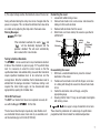
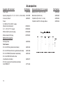
M
OTS60SX
Semi Automatic Oil Test Set
User Manual
99 Washington Street
Melrose, MA 02176
Phone 781-665-1400
Toll Free 1-800-517-8431
Visit us at www.TestEquipmentDepot.com
Contents
Guide de l’utilisateur - p14
Gebrauchsanleitung - s24
Safety Warnings
3
Preparing the Oil Test Set
5
General Description
Operation
Oil Sampling
Preparing the Oil Test Vessel
Control Panel
Breakdown Testing
Withstand Testing
Warning messages
Testing to National Standards
Sampling and Testing Oil for Dielectric strength
4
5
5
5
6
6
6
7
7
8
Oil Testing Specifications
10
Accessories
12
Test Set Specification
Repair and Warranty
2.
10
13
Guía del usuario - p34
SAFETY WARNINGS
•
•
•
•
•
•
•
Safety warnings and precautions must be read and understood before the instrument is used.
They must be observed during use.
The oil test set must be properly earthed.
The test chamber must be kept scrupulously clean.
If the test chamber cover is cracked or damaged in any way the test set must not be used, but sent
for repair to an authorised agent.
The chamber door hinges are fitted with earth contact springs. These must not be damaged or
corroded.
The correct type of oil test vessel must be used, and correctly positioned on the support horns
before carrying out any testing.
Replacement fuses must be of the correct type and rating.
NOTE
THE TEST SET MUST ONLY BE USED BY SUITABLY TRAINED AND COMPETENT PERSONS.
Symbols used on the Test Set
Caution: Refer to accompanying notes.
Risk of electric shock.
Equipment complies with relevant EU Directives
3.
General Description
The OTS60SX is a lightweight, semi-automatic, oil dielectric
strength test set. The instrument is suitable for protected field
use and can be powered from a range of mains supplies. The
maximum 60 kV output allows tests to be performed on oil from
a wide variety of electrical installations including transformers,
circuit breakers and other equipment. The operation of the test
set is extremely simple and the results are displayed on a bright
LED display. A selection of vessels enables the instrument to be
configured for a variety of tests.
Voltage
Selector
The semi automatic operation allows all types of testing to be
performed. An automatic one minute timer operates when the
high voltage is paused for Withstand (proof) testing. Oil samples
can also be tested according to breakdown specification by using
a suitable sequence of tests.
The instrument is constructed in a strong, sheet steel case.
Handles are provided for ease of transportation. A pouch is
located on the side of the instrument to contain accessories such
as the power cord, additional electrodes and the spacing gauge.
An optional carrying case incorporates a shoulder strap.
Fuseholders
Mains
power
input
A number of vessels are available suitable for testing to a wide
range of national specifications. Three types of electrode are
available; spherical (IEC type), mushroom (VDE/ASTM D1816)
and cylindrical (ASTM D877). The oil sample can be stirred by a
motor driven impeller available in selected vessels. The vessel is
located in the top of the instrument and covered by a transparent
polycarbonate door with a mesh screen so that the oil breakdown
can be viewed. A safety interlock ensures that the high voltage is
disconnected when the chamber door is opened.
Mains Input Panel
4.
Preparing the Oil Test Set
Ensure that the instrument is properly earthed. The test set must
be connected to a socket (receptacle) with a protective earth
(ground) conductor.
Before connecting the instrument to the mains power supply,
ensure the voltage selector located on the mains input panel is
set to the required voltage. The correct fuse value should be
fitted for the supply voltage (See Specification). The fuse
holders are located next to the supply inlet.
Power cord
If the power cord plug is not suitable for your type of socket
outlets, do not use an adaptor. You should use a suitable
alternative power cord, or if necessary change the plug by cutting
the cord and fitting a suitable plug.
The colour code of the cord is:
Earth (Ground)
Yellow / Green
Phase (Line)
Brown
Neutral
Blue
If using a fused plug, a 3 Amp fuse to BS 1362 should be fitted.
Note: A plug severed from the power cord should be destroyed,
as a plug with bare conductors is hazardous in a live socket
outlet.
Operation
Oil Sampling
The relevant test specification will give advice on the best
methods to use when sampling oil. Contamination of the oil may
lead to misleading results. Always run off a small amount of oil
before sampling and ensure that the flow of oil is steady.
Preparing the Oil Test Vessel
Optional vessels are available for testing to national
specifications (See table and Accessories). Some
specifications require stirring of the oil sample as well as different
test electrode shapes. Once the correct vessel has been chosen
for the required test the electrode gap should be set. This is
achieved by adjusting the threaded nut on the side of the vessel.
Small adjustment of the gap can be made by hand tightening the
nuts and rotating the spindle. A slot is provided on the end of the
spindle for this purpose.
A set of individual 0,5mm feeler gauges is provided for accurate
measurement of the gap. Gauges can be combined to measure
from 1mm to 4mm. (see page 12)
Clean the vessel in accordance with the instructions given in the
relevant test specification. Allowing space for the lid to be fitted,
fill the vessel with the oil sample. The amount of oil required will
depend upon the type of lid used. Load the vessel in the test
chamber, connecting the motor power cable, if fitted, and
carefully shut the door so that the safety interlock switch
operates.
5
LED
Display
Control Panel
The control panel contains the supply on/off switch, the high
voltage display, voltage ramp rate selection and the three control
keys. The operation of the instrument is very simple. When the
instrument is turned on, the on/off switch is illuminated, and the
software edition code will be flashed up on the display.
s
Breakdown Testing
The suitable ramp rate for the test to be performed should be
selected using the ‘s' key. The START key ‘ ‘ will then turn on
the high voltage. The red H.V. indicator will light to show the
output voltage is on. The voltage will then increase at the
selected ramp rate and the corresponding value will be shown on
the display. If oil breakdown occurs the instrument will detect this
and immediately shut off the high voltage. The breakdown
voltage value will be left on the display until the next test is
started. If no breakdown occurs, the high voltage will rise to
60 kV. At this point the test voltage is cut off and this maximum
value left on the display.
Main
controls
Ramp rate
selection
Mains
on/off
switch
HV on
indicator
Control Panel
6.
A test can be stopped at any time by pressing the STOP ‘n’
button. This will remove the high voltage from the oil sample and
leave the display at 0,0 kV.
Withstand Testing
A Withstand (proof) test can be carried out by pressing the
PAUSE ‘ ‘ key. This will maintain the high voltage at the current
value for one minute. After this time the high voltage will continue
to rise until one of the following:1) Oil breakdown occurs
2) The STOP ‘n' key is pressed
3) The output voltage reaches the maximum value of the test set.
During withstand testing the ramp rate can be changed while the
pause is in progress. This can allow the withstand test value to be
accurately set by adjusting the ramp rate to the lowest value.
Warning Messages
Door Open
If the instrument overheats, the words ‘
‘ and
‘ will be alternately displayed and the
‘
operation disabled. This will reset automatically,
when cooled, after a few minutes.
Testing to National Standards
The OTS60SX can be used to test to any international standard.
A table of the standards is given on page 10. To perform these
tests it is necessary to select the correct vessel so that the
specified electrodes and suitable stirring are used. Most standards
require repetitive breakdown tests to be carried out and the
average taken. Note that sometimes the first breakdown result is
omitted from the average calculation. If continuous stirring is not
required the stirrer motor supply can be disconnected when
appropriate by opening the chamber door.
100 ml Oil Test Vessel
The D877 Low Volume Test Vessel is an optional accessory for
use with the Megger® OTS60SX Oil Test Set.
The test vessel must be kept scrupulously clean. Before each
use, dismantle the test vessel, clean and dry, re-assemble, and
set the electrode gap to 2,54 mm (0.100 inch).
Dismantling the vessel
1.
Loosen both white locking screws.
2.
Hold each electrode in turn, and unscrew, and remove the
sliding arm from each electrode.
3.
Remove both electrodes from the vessel.
4.
Wash hands, and clean and dry the vessel as specified in
ASTM D.877.
Fill level
Electrode
Locking
screw
Viton
(Oil resistant)
‘O’ Ring
Sliding arm
Re-assembling the vessel
1.
With clean, uncontaminated hands, place the cleaned
electrodes in the vessel.
Position each electrode in turn with the fingers, and screw
2.
in a sliding arm through the vessel into the each electrode
in turn.
3.
Centre the electrodes, and set the gap, using the
appropriate gauge.
4.
Ensuring that the Viton ‘O’ rings are not fouled, hand tighten
both locking screws.
Megger Limited also supply a range of automatic oil test sets.
These have the parameters of a wide range of specifications
programmed into the instrument for unattended operation.
7
Sampling and Testing Oil for Dielectric Strength
The following notes should be read in conjunction with the relevant
oil testing specifications.
Causes of Bad Oil
Transformers and switchgear oil may be rendered unsuitable for
further use due to four main reasons:Low dielectric strength.
1.
2.
High acidity.
3.
High sludge content.
4.
Excessive free water content.
Low dielectric strength may result from many causes, the most
common of which is foreign particles or fibres and water in
combination. Individually their effect may be relatively small, but
together a contamination of only a few parts in a million can cause
considerable lowering of the breakdown voltage of the oil. High
acidity, sludge and free water should not be tolerated, but will not
necessarily reduce the dielectric strength below acceptable or
specified levels.
Appearance of the Sample
Only an experienced person can judge the condition of an
insulating oil from its appearance, but a general guide may be
obtained from the following observations:1.
A cloudy appearance may indicate that sludge has
been formed.
2.
A dark yellow colour could be a sign of overheating.
3.
A blackish colour often results from an arc having taken
place with either carbonisation of the oil or of the
insulation within the equipment.
4.
A green colour may be due to copper salts dissolving
in the oil.
8
Cleanliness of the Apparatus
The necessity for scrupulous cleanliness
during the process of sampling, cannot be
measurement of the dielectric strength
dependent on the cleanliness of the test
apparatus as the condition of the oil itself.
in the apparatus and
over emphasised. The
of the sample is as
cell and the sampling
After cleaning the apparatus, it should under no circumstances be
wiped, dried or even handled with a dusty or fibrous cloth as loose
dust or fibres are liable to cause contamination.
Precautions Necessary During Sampling
Since the oil taken from a drain cock will inevitably contain an
excess of settled out solid impurities, and will not necessarily be
representative of the bulk of the oil, it should be run to waste until
clear.
Always run off a quantity of oil into a glass bottle or a test tube for
an initial check on the appearance of the oil. Attention to this point
may prevent contamination of a clean test vessel.
If necessary, thoroughly clean and dry the sample point using a
suitable solvent. Any cloth used should be lint free. Open the
sample cock and drain to waste enough oil to ensure that the
sample cock is fully flushed and the sample is representative of
the bulk of oil to be tested. This quantity will depend upon the size
of the transformer or main container. About 2 litres is usually
suitable.
When sampling from a drum or supply container, the oil should
flow at a steady rate into the test vessel and after being swilled
around the sides it should be discarded. Without altering the rate
of flow of the oil the quantity required for the test should then be
run off while taking extreme care to prevent the ingress of
atmospheric dust, cloth fibres or moisture.
Do not use a syphon. In the absence of a useable sample point,
use a ‘thief’.
Shield the sample from direct light until ready to be tested.
Turbulence and air bubbles should be avoided when pouring the
oil. Relevant national specifications should be observed.
Particular care to prevent contamination is necessary when a
test is to be made on a bulk delivery tanker, and on all occasions
when a high value of dielectric strength is anticipated. The
procedure suggested above should be rigorously applied.
9
Oil Testing Specifications
2.54mm
Continuous/None
Continuous/None
10
Output voltage
0 - 60 kV rms
Transformer rating
500 VA
Test Frequency
Output disconnection
Power supply
Fuses
Operation
Display
Measurement Accuracy
Controls
Safety
EMC
Temperature Range
Humidity Range
Dimensions
Weight
Cleaning
Specification
61,8 Hz
Within 1 ms of detection of breakdown
115 V (99 - 132 V), 230 V (198 - 264 V) (switch selectable) 50/60 Hz, 80 VA
500 mA (T) HBC to IEC127/5 for 220/240 V supply
1 A (T) HRC to IEC127/5 for 110/120 V supply
Mains power cord fused plug (when applicable): 3 Amp to BS1362
Semi automatic with 0,5, 2 or 3 kV/s selectable rate of voltage rise
Pause function with automatic 1 minute timer for Withstand testing
0,0 - 60,0 kV LED digital display
HV on LED
Ramp rate LED
2% ± 3 digits
Start, Pause, Stop, Ramp Rate select and Power On/Off switch
The instrument meets the requirements of IEC 61010-1
In accordance with IEC 61326-1
Operating:
Storage:
0 to 40 ºC
-40 to +70 ºC
Operating:
Storage:
80% RH at 40 ºC
93% RH at 40 ºC, 95% RH at 25 ºC
336 mm (13,2 in) (H) x 400 mm (5,7 in) (L) x 235 mm (9,3 in) (D)
17,5 kg (38,5 lb)
Wipe disconnected test set with a clean cloth dampened with soapy water or Isopropyl Alcohol (IPA)
11
Supplied with Instrument
User Guide
Accessories
Part Number
6172-120
Spherical (12,7 mm, 0,5 in. dia.)
6320-232
Cylindrical (25,4 mm, 1 in. dia.)
Spacing Gauge (0,5, 1,0, 1,5, 2,0, 2,5, 2,54 & 4mm) 6132-009
Accessory Pouch
Fuses:
2 x 500 mA (T) for 230 V supply
(fitted to the instrument)
25950-014
Mains lead (fit your own plug)
25424-860
2 x 1 A (T) for 115 V supply
Mains lead with US plug
Optional Accessories
25970-002
6420-106
0,5 l for IEC156 (spherical electrodes)
6320-233
0,5 l for VDE0370 (mushroom electrodes)
6320-234
0,5 l for IEC156 with stirrer (spherical electrodes)
0,5 l for ASTM D1816 with stirrer
(mushroom electrodes)
0.15 litre vessel with cylindrical electrodes
for ASTMD 877
12
6320-236
6320-237
6111-356
Part Number
6220-484
Mushroom (36 mm dia.)
6220-580
Cylindrical with 0,5 mm edge radius
6220-538
25950-004
Carrying Case
Test Vessels
Spare electrodes for 0.5 L vessels
6220-483
Guage Indentification
1mm
2mm
2.5mm 2.54mm
4mm
5152-293 5152-294 5152-296 5152-319 5152-296
Rings
1
2
3
4
Repair and Warranty
The instrument circuit contains static sensitive devices, and care
must be taken in handling the printed circuit board. If the
protection of an instrument has been impaired it should not be
used, and be sent for repair by suitably trained and qualified
personnel. The protection is likely to be impaired if, for example,
the instrument shows visible damage, fails to perform the
intended measurements, has been subjected to prolonged
storage under unfavourable conditions, or has been exposed to
severe transport stresses.
New Instruments are Guaranteed for 1 Year from the Date of
Purchase by the User.
Note: Any unauthorized prior repair or adjustment will
automatically invalidate the Warranty.
Approved Repair Companies
A number of independent instrument repair companies have been
approved
for
repair
work
on
most
Megger
instruments, using genuine Megger spare parts. Consult the
Appointed Distributor / Agent regarding spare parts, repair
facilities and advice on the best course of action to take.
Returning an Instrument for Repair
If returning an instrument to the manufacturer for repair, it should
be sent freight pre -paid to the appropriate address. A copy of the
Invoice and of the packing note should be sent
simultaneously by airmail to expedite clearance through
Customs. A repair estimate showing freight return and other
charges will be submitted to the sender, if required, before work
on the instrument commences.
Test Equipment Depot - 800.517.8431 - 99 Washington Street Melrose, MA 02176
TestEquipmentDepot.com
13