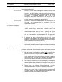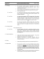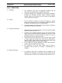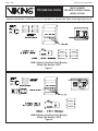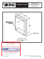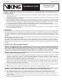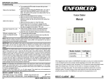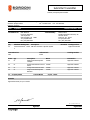
1
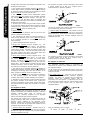
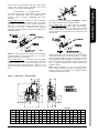
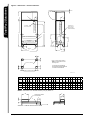
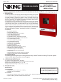
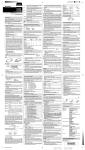
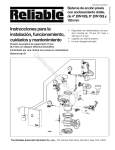
Submittal Transmittal Detailed, Grouped by Each Number 4719 - Kirby Center for the Creative Arts WyomProject # 4719 201 North Sprague Street Tel: 570-283-0744 Kingston, PA 18704 Date: Fax: 570-283-0811 7/9/2013 Transmitted To: Reference Number: 0127 Transmitted By: Mark Molitoris K & K Fire Protection 1793 Layton Rd Scott Township, PA 18447 Tel: (570)586-0910 Fax: (570) 586-8760 Qty Submittal Package No Description 04 2100-210504-0002 - 13900 - K&K Fire Protection: Sprinkler System 0 Melissa James Sordoni Construction Services, Inc. 45 Owen Street Forty Fort, PA 18704 Tel: (570) 287-3161 Fax: (570) 287-0298 Due Date Transmitted For Delivered Via Files E-Mail Package Action Approved as Noted Tracking Number Items Qty Description Notes Item Action 01 01 210504 Approved as Noted 02 01 Single Interlocked Systems Totalpac Deluge Valve Release Control Panel 210504 Approved as Noted 03 01 01 Deluge Valve Solenoid Valve Single Interlocked Systems Batteries 210504 210504 Approved as Noted Approved as Noted 04 Cc: Company Name Contact Name Copies Notes Remarks Approved as Noted, for your records. 07/09/2013 Signature Printed on: 7/9/2013 SCS PA Signed Date Page 1 SUBMITTAL REVIEW X N. Burden SUBMITTAL: 6-26-13 210504-0002 Pre-action Sprinkler System General Notes: • Review attached submittal as well as any previously returned submittals for additional comments. • Present copies of submittals to other contractors as required for coordination and review. COMMENTS: 1. Submittal 210502-0002: Provide air-compressor and pre-action assembly cabinet. X 06.29.13 KM Wyoming Seminary Kirby Center PAI Project No. JCJA1004 Submittal Transmittal Detailed, Grouped by Each Number 4719 - Kirby Center for the Creative Arts WyomProject # 4719 201 North Sprague Street Tel: 570-283-0744 Kingston, PA 18704 Date: Fax: 570-283-0811 6/26/2013 Transmitted To: Reference Number: 0119 Transmitted By: Karl Metz JCJ Architectural New York, NY 10017 Tel: (212) 774-3606 Fax: (212) 774-3607 Qty Submittal Package No Description 04 2100-210504-0002 - 13900 - K&K Fire Protection: Sprinkler System 0 Due Date Transmitted For Delivered Via Approval E-Mail Items Qty Description Notes 01 01 210504 02 01 Single Interlocked Systems Totalpac Deluge Valve Release Control Panel 03 01 01 Deluge Valve Solenoid Valve SIngle Interlocked Systems Batteries 210504 210504 04 Cc: Company Name Melissa James Sordoni Construction Services, Inc. 45 Owen Street Forty Fort, PA 18704 Tel: (570) 287-3161 Fax: (570) 287-0298 Contact Name Package Action 7/10/2013 Tracking Number Item Action 210504 Copies Notes Remarks For your review and approval. 06/26/2013 Signature Printed on: 6/26/2013 SCS PA Signed Date Page 1 TOTALPAC2 Page 1 of 4 TOTALPAC2 Integrated Fire Protection System General description - Preaction Single Interlocked General 1. Applicable Standards 3. Environment TOTALPAC2 units shall be installed in a dry and clean location. Verify that all equipment is properly heated and protected to prevent freezing and physical damage. The unit and its components must be kept free of foreign matter, freezing conditions, corrosive atmospheres, contaminated water supplies, and any condition that could impair its operation or damage the components. The TOTALPAC2 complies with the following standards: - NFPA-13 Sprinkler Systems; - NFPA-15 Water Spray Fixed Systems; - NFPA-16 Foam-Water Sprinkler and Foam-Water Spray Systems; - NFPA-72 Fire Alarm Systems. Before installation, the contractor installing the unit shall also be familiar with the following documents and standards: - Applicable Local & State Building Codes - Any additional requirements of the Local Authority Having Jurisdiction. The frequency of the inspections and maintenance will vary depending on these environmental conditions as well as the condition of the air supply to the system. The owner is responsible for maintaining the fire protection system and devices in proper operating condition. Refer to MECHANICAL SECTION for maintenance instructions. 2. Listings and Approvals In addition to being fabricated under tight ISO-9001 manufacturing and quality control procedures, your TOTALPAC2 Unit has also been tested and approved by recognized laboratories. Here is the list of Listings & Approvals it meets: - Underwriters Laboratories Inc. (UL): Preaction TotalPac2 systems are UL Listed under "Special System Water Control Valves - Assembled Units, category # VKYL.EX4641" and "Assembled Units Certified for Canada, Category # VKYL7.EX4641 (CUL)". - Factory Mutual Research <FM>: Preaction TotalPac2 systems are FM Approved under the heading: "Automatic Water Control Valves" when installed with specific components. - California State Fire Marshal <CSFM>: Preaction TotalPac2 systems are CSFM Approved under the heading: Misc. Devices/Control Unit Accessories, Listing No. 7300-0533:107. FIELD CHECKED Subject to Contract Plans & Specifications By swycoski at 8:42 am, Jun 25, 2013 SORDONI CONSTRUCTION SERVICES BY: Note: Although most TOTALPAC2 units are Listed and Approved, custom built units are sometimes supplied on request. Components in these special units maintain their individual Listings/Approvals but the units are not Listed as an assembled unit. WARNING ! Any unauthorized modification or addition made on-site to a factory built Listed Unit will void this Listing. Such modifications or additions may void the unit's warranty as well. Consult your nearest FireFlex Systems Authorized Distributor before proceeding with such modifications or additions. FM-086G-0-49D TOTALPAC2 Page 2 of 4 TOTALPAC2 Integrated Fire Protection System General description - Preaction Single Interlocked 4. General Description There are several types of preaction systems, however all of them use closed automatic sprinklers in the sprinkler piping. A detection network or system is used in parallel with the automatic sprinkler system and is designed to operate before a sprinkler head fuses. This network may be hydraulic, pneumatic or electric and may be actuated by manual, fixed temperature, rate-of-rise temperature, smoke or other means. Detection system operates before the sprinkler fuses and gives an alarm. Because preaction systems are often used in freezing areas, electrical and pneumatic detection systems are by far the most common. This TOTALPAC2 integrated fire protection system by FireFlex Systems Inc. consists of a preaction system trim totally pre-assembled, pre-wired and factory tested. All electrical and mechanical components of the system are contained in one single unit. Note: Skid units include the trim components only and must be wired by the installing contractor. The most common applications are very large dry systems which exceed the capacity normally permitted on a dry valve and in a system application where it is important to control accidental water discharge due to damaged sprinkler piping. The only connections required for installation are the water supply inlet, water discharge outlet, main drain, the electrical detection and alarm connections, as well as the AC power line(s). The discharge outlet is connected to a fixed piping system of automatic sprinklers. Water is the extinguishing agent. Single interlocked preaction systems are designed so the Deluge valve will open ONLY when a detector on the electric release system OR on the pneumatic release system operates. A loss of pressure in the sprinkler system will only cause a supervisory condition. When the Deluge Valve opens, water will flow into the sprinkler piping and out of open sprinklers and any opening on the system. Note: Every TOTALPAC2 Unit is identified with its unique Serial Number. This number is located on an adhesive label inside the main door panel and is used to maintain a record in our computerized data base. Have this Serial Number handy when calling for information on your unit (format is TOT2#### or TOTS#### for Skid Units). FM-086G-0-49D 5. Features The TOTALPAC2 unit is superior to many other products available on the market now, and has been manufactured by the company that has introduced and developed the concept of integrated fire protection systems in the market. Main features are: - Trouble free design for safe and easy application - Available in 5 sizes from 1½" to 6" diameter - Uses the Viking Deluge Valves - Units available either with or without Integrated Control Panel, but is provided by others on Skid version - Skid version without control panel available - Compact, aesthetic and easy to move - User-friendly standardized owner's manual with every unit - Unique serial number on every unit - Uses only UL, C-UL Listed and FM Approved components - Designed in accordance with NFPA Standards - Trim is fully assembled and tested at the factory - All trims are galvanized steel, Listed and Approved for 250 psi (1724 kPa) service maximum. - Quick connections to water supply and drain on both sides, and sprinkler riser on top of unit, all available with grooved end or flanged fittings - No open drain cup inside unit - Sturdy 14 Gauge steel cabinet or skid, painted fire red with oven baked polyester powder on phosphate base - Textured rust proof finish - Neoprene gasket on all doors to eliminate vibrations - Easily removable doors for ease of access - Separate unlocked access hatch to emergency manual release - Key-alike locks on all cabinet doors - Manufactured under ISO-9001 quality control procedures. TOTALPAC2 Page 3 of 4 TOTALPAC2 Integrated Fire Protection System General description - Preaction Single Interlocked 6 Configuration Description TOTALPAC2 Preaction systems are built around the Viking Trim using Deluge Valves Model E-3 for 1½" (40 mm) diameter (Model E-4 is the Halar® Coated version for use in corrosive environments) and Model E-1 for 2" (50 mm) ® diameter and up (Model E-2 is the Halar Coated version for use in corrosive environments). All the valves are rated up to a maximum of 250 psi WWP (1724 kPa) max. and are available in the following diameters: f 1½" (40 mm) f 3" (80 mm) f 6" (150 mm) f 2" (50 mm) f 4" (100 mm) TotalPac2 Preaction systems are supplied with flange– groove Deluge Valves. Units with flange–flange Deluge Valves are also available on request. Preaction systems operate in several ways and perform a variety of functions. Following is a summary of the most common types of systems: Single Interlocked. This preaction system utilizes a detection system and pressurized air or gas in the sprinkler piping. This preaction may be opened either by the fusing of a sprinkler in the sprinkler piping, by the operation of the detection system or anytime the handle of the Emergency Release Valve is pulled. The sprinkler piping contains air or nitrogen gas under pressure. This preaction system requires the operation of the detection system to trip the Viking Deluge Valve and fill the system with water. Water will then be discharged on the fire when the sprinklers fuse. If the sprinkler piping or sprinkler is broken, the valve will not open. If the detection system operates due to fire, damage or malfunction, the valve will open but the water will be contained in the sprinkler piping. If the detection system does not operate, the deluge valve will not open. Supervision is generally used since control of accidental discharge is usually desired. The single interlocked preaction system is commonly used where it is preferable to have water available at the sprinkler when the sprinkler fuses and where the sprinkler piping is subject to damage. The most common applications are very large dry systems which exceed the capacity normally permitted on a dry valve and in a system application where it is important to control accidental water discharge due to damaged sprinkler piping. Available release systems are: Pneumatic or electric. 7 System Release Note: Numbers indicated between brackets refer to items on the TRIM and AIR SUPPLY SCHEMATICS. 7a- Pneumatic Release Pneumatically controlled preaction systems require a pneumatic release system, equipped with thermostatic (rate of rise) releases, and/or fixed temperature releases, and/or pilot heads. Release trim for the pneumatically controlled deluge valve requires a pneumatic actuator normally held closed by pressure maintained in the pneumatic release system. In fire conditions, operation of the pneumatic release system opens the deluge valve to fill the system with water. If any sprinklers have opened, water will flow from the system. If sprinklers have not opened, water will be in the sprinkler system piping when the sprinkler operates. A sprinkler head must open before water flows from the system. Note: The air supply for the pneumatic release piping system must be provided by the contractor and installed outside the TOTALPAC2 unit. The air supply must be restricted to ensure that the automatic air supply cannot replace air as fast as it escapes when a releasing device or sprinkler operates. It is also recommended to provide Inspectors Test Connections on both the release system and the sprinkler system. 7b- Electric Release Release trim for the electrically operated Single-Interlocked Preaction system utilizes an electric solenoid valve (F1) controlled by an approved system control panel with a compatible detection system (if provided with this system, see Controls Section and VFR-400 manual for details). In fire condition, when the detection condition is satisfied the system Control Panel energizes the Solenoid Valve (F.1) open, causing the Deluge Valve (A1) to open. If any sprinklers have opened, water will flow from the system. If sprinklers have not opened, water will be in the sprinkler system piping when the sprinkler operates. A sprinkler head must open before water flows from the system. FM-086G-0-49D TOTALPAC2 Page 4 of 4 TOTALPAC2 Integrated Fire Protection System General description - Preaction Single Interlocked This page was intentionally left blank FM-086G-0-49D Systems Inc. 1935, Lionel-Bertrand Blvd. Boisbriand, Quebec, Canada J7H 1N8 Tel.: (450) 437-3473 Fax: (450) 437-1930 Toll Free: (866) 347-3353 Web Site: http://www.fireflex.com TOTALPAC2 Integrated Fire Protection Systems Standard Specifications Preaction System Single Interlocked – Electric Release (Remote Controlled Unit) FM-072D-0-76 B Sept. 2008 Fire Protection Division 13 Remote Controlled Preaction System Single Interlocked with Electric Release Section 13940 - Table of Contents Part 1 - GENERAL 1.0 1.1 1.2 1.3 1.4 1.5 1.6 Related Work in Other Sections .................................................................................... 3 Standards & Rules......................................................................................................... 3 System Description........................................................................................................ 3 System Design............................................................................................................... 3 Drawings & Hydraulic Calculations ............................................................................... 4 Technical Data............................................................................................................... 4 Maintenance & Operation Manual................................................................................. 4 Part 2 - COMPONENTS 2.1 2.2 2.3 2.4 2.5 2.6 2.7 2.8 2.9 Preaction Cabinet .......................................................................................................... 5 Cabinet Options ............................................................................................................. 6 Detection & Signaling Devices ...................................................................................... 6 System Operation .......................................................................................................... 6 Air Supply ...................................................................................................................... 7 Air Supply Options ......................................................................................................... 7 Automatic Sprinklers...................................................................................................... 7 Piping............................................................................................................................. 7 System Drain ................................................................................................................. 7 Part 3 - EXECUTION 3.1 3.2 3.3 3.4 Installation...................................................................................................................... 8 Training.......................................................................................................................... 8 Tests and Verifications .................................................................................................. 8 Report & Certificate ....................................................................................................... 8 IMPORTANT Due to variable job conditions or additional requirements requested by owner or Authorities Having Jurisdiction this document is intended as an information guide only, not as a final project design. The consulting engineer should make appropriate adjustments for the project involved. Fire Protection Division 13 Remote Controlled Preaction System Single Interlocked with Electric Release Section 13940 3 Part 1 - GENERAL 1.0 Related Work in Other Sections Yes No 1.1 Standards & Rules .1 Fire Protection General Prescription Division 13, Section 13940 .2 Electrical Division 13, Section 13850 Choose applicable option: .1 Supply and install one dedicated 110VAC, 60Hz branch circuit to power the air compressor provided inside the preaction cabinet by the factory (alternate: 220Vac, 50Hz outside North America - choose one). .2 The independent circuit shall be well identified and its circuit breaker locked. .1 .2 .3 .4 .5 .6 .7 .8 .9 1.2 System Description .1 .2 NFPA 13 (Installation of Sprinkler Systems) NFPA 25 (Inspection, Testing, and Maintenance of Water- Based Fire Protection Systems) NFPA 72 (Standard for the Installation, Maintenance, and Use of Protective Signaling Systems) NFPA 72E (Standard on Automatic Fire Detectors) CAN/ULC-S524 (Standard for the Installation of Fire Alarm Systems) – For Canada only ! CAN/ULC-S537 (Standard for the Verification of Fire Alarm Systems) – For Canada only ! National Building Code National Fire Code National Electrical Code Supply and install a remote controlled TotalPac2 integrated fire protection system, preaction type as indicated, including: - Preaction cabinet - Automatic sprinkler system - Fire detection system The integrated unit shall be c-UL-us Listed and FM Approved as an assembled unit. All system components shall be "compatible", UL/ULC listed or FM approved. Note: The word compatible used in this specification means that the items concerned have been tested and listed and/or approved for their use together. 1.3 System Design .1 .2 The system must be designed for: - occupancy hazard: - density gpm/sq. ft. ( L/min./m²) sq. ft. ( m²). - area of sprinkler operation Water supply: Location: Static pressure: psi ( kPa) Residual pressure: psi ( kPa) Water flow: gal/min. ( L/min.) Fire Protection Division 13 Remote Controlled Preaction System Single Interlocked with Electric Release Section 13940 4 1.3 System Design (Cont'd) 1.4 Drawings & Hydraulic Calculations 1.5 Technical Data 1.6 Maintenance & Operation Manual .3 The maximum area coverage per smoke or heat detector shall meet NFPA-72 requirements and not exceed the manufacturer's recommendations. .1 The fire protection contractor must prepare and submit for the engineer's approval all installation drawings and hydraulic calculations, as required by NFPA. .1 Submit for the engineer's approval a set equipment data sheets which will include all technical data of each essential component of the system such as integrated unit and options, automatic sprinklers, control system, etc. .1 Supply a standardized and listed Maintenance & Operation manual for the preaction system. This manual must include all necessary instructions to operate and maintain the system, and be explicit regarding the interaction between the hydraulic aspect (deluge valve and trim) and the detection portion (remote control panel provided by others or existing). Emergency procedures must form an integral part of the manual. Supply a separate user manual for the air compressor (when applicable). .2 .3 Fire Protection Division 13 Remote Controlled Preaction System Single Interlocked with Electric Release Section 13940 5 Part 2 - COMPONENTS 2.1 Preaction Cabinet .1 .2 Supply and install a remote controlled (without control panel) preaction cabinet single interlock with electric release containing all hydraulic and electrical components required for the control of a preaction system. The cabinet shall include the following: - Remote controlled unit (without control panel) in sturdy freestanding 14 gauge steel cabinet, measuring: - 57" x 36" x 20" (145 x 91 x 51cm) for 1½", 2" & 3" systems; - 57" x 46" x 24" (145 x 117 x 61cm) for 4" & 6" systems. - Textured rust proof coating, inside and outside, fire red, oven baked polyester powder on phosphate base (powder coated). - Two locked access doors to reduce front area required for opening, easily removable without tools to allow easy installation & servicing. - Individual access doors for the hydraulic section and the emergency release with a neoprene gasket to avoid vibrations. - Viking Deluge Valve model E, complete with releasing trim rated at 250 psi and all the necessary accessories. Trim shall include a mechanical latching device to prevent system from resetting in case of loss of power to the release solenoid. Systems provided with solenoid only, without this mechanical latching device shall not be accepted. Every valve shall be clearly identified as to its operation with arrows indicating all positions to facilitate system operation. - Pressure gauges to indicate water supply, priming water and air pressures of the system. Each pressure gauge must be provided with its own shut-off valve and shall be clearly identified on the outside of the cabinet front door. - Schedule 40 galvanized steel release trim with solenoid valve and each supervisory and alarm device required. Black pipe will not be accepted. - Schedule 40 steel pipe header painted fire red, with grooved ends to be connected to supply water from either side. - Schedule 40 steel pipe drain manifold of 2" diameter painted fire red, with grooved ends to be connected to drain connections from either side. - Properly identified contractor test ports factory mounted into the trim piping to facilitate system testing and commissioning. - Field wiring terminal strips integrated with the cabinet for connection of field wiring for remote detection system, audible devices, auxiliary contacts and power supply for the optional air compressor. The cabinet assembly must be pre-assembled, pre-wired and factory tested under ISO-9001 conditions, as a Viking TotalPac2 System, by FireFlex Systems Inc. It shall also be c-UL-us Listed and FM Approved as an assembled unit. Fire Protection Division 13 Remote Controlled Preaction System Single Interlocked with Electric Release Section 13940 6 2.2 Cabinet Options: Choose applicable options: Yes No Provide a second Listed and Approved isolation butterfly valve installed on the system riser inside the cabinet for full flow test purposes. The valve shall be supervised by the same supervisory circuit as the system main water supply valve tamper and wired at the factory. An integrated sight glass shall be part of this arrangement for visually confirming water flow through the drain upon system actuation. A detailed instructions placard must be provided inside the cabinet door for easy reference. Yes No Provide a tee connection inside the cabinet with an opening on the right side of the cabinet enclosure for connection to the Fire Department Connection. 2.3 Detection & Signaling System 2.4 System Operation .1 Supply and install a partial electrical detection system including: - system tubing, wiring, solenoid valve, signaling devices and connections to auxiliary functions. .2 Heat and/or smoke detectors shall be provided and wired to the remote release control panel by others. Spacing and type of detectors shall meet the requirements of the applicable standards and the manufacturer's recommendations for the application protected. .3 All detection and alarm indicating devices (24 Vdc bell, horn or strobe) must be compatible with the remote release control panel. In addition, contractor should ensure that the remote control panel is Listed and/or Approved for releasing service. .4 A bell or a horn should be installed near the TotalPac2 cabinet. Note: Refer to the applicable compatible device list of the remote release control panel to determine which compatible initiating and signaling devices model number to use. Contractor should make sure the remote release control panel sequence of operation is programmed to perform the following: .1 Both the activation of the detection condition AND the opening of an automatic sprinkler are necessary to cause the water discharge. .2 The activation of the detection condition will activate the solenoid valve, open the deluge valve and cause the system to fill the piping network with water. This will sound an alarm and activate alarm and water flow contacts connected to the remote control panel. .3 The opening of an automatic sprinkler or damage to system piping without the detection condition satisfied will activate an alarm contact connected to the remote control panel but will not cause the system to fill. .4 Pressure loss on the sprinkler system will activate an auxiliary contact indicating same, connected to the remote control panel. .5 Operation of the emergency manual release will drain the priming chamber of the deluge valve, causing the system to immediately fill the piping network with water, and activate alarm and water flow contacts connected to the building fire alarm panel. Fire Protection Division 13 2.5 Air Supply Remote Controlled Preaction System Single Interlocked with Electric Release .1 .2 .3 Section 13940 7 The automatic sprinkler piping is supervised by air from a compressed air source installed inside (alternate: outside – Choose one) the preaction cabinet. The air supply must be regulated and of the proper size in order to be able to restore normal system air pressure within 30 minutes. Choose applicable style: Air compressor and supervisory trim (Air Supply Style "A") shall be factory installed inside the cabinet and its pressure adjusted for the selected configuration. OR Air supply and supervisory trim (Air Supply Style "B") shall be provided inside the cabinet and its pressure factory adjusted for the selected configuration. Supply and connection to an external air compressor (alternate: nitrogen cyclinders – Choose one) properly sized for the system shall be made by the contractor on-site. Yes No Yes No OR Air supply and supervisory trim (Air Supply Style "D") shall be factory installed inside the cabinet and provide supervisory and control only when the air supply is from plant air or provided by others. Yes No 2.6 Air Supply Options Choose applicable options: Yes No .1 For high humidity environments, a dehydrator assembly must be factory installed in the air trim, with bowl guard, supply control and drain valves. Dehydrator shall be Viking manually generated dessicant-type air dryer, the dessicant acting as a moisture indicator by changing color. .1 .2 Supply and install all required automatic sprinklers. They will be glass bulb type, UL/ULC listed and FM approved. Applicable specifications of automatic sprinklers shall be determined as per the manufacturer recommendations, based on the project conditions. .1 System piping and fittings shall be as recommended by NFPA 13. .1 The single drain collector of the Viking TotalPac2 System shall be connected to an open drain (open end pipe with an air gap around the drain pipe or equivalent). The drain piping shall not be restricted or reduced and shall be of the same diameter as the drain collector. It shall also be arranged to avoid back-pressurizing the drain trim. Multiple drain collectors and open drain cups inside the cabinet will not be accepted. Manifolding of multiple units is permited provided the manufacturer's recommendations are carefully followed and complied with. 2.7 Automatic Sprinklers 2.8 Piping 2.9 System Drain .2 Fire Protection Division 13 Remote Controlled Preaction System Single Interlocked with Electric Release Section 13940 8 Part 3 - EXECUTION 3.1 Installation .1 .2 3.2 Training .1 .2 3.3 Tests and Verifications .1 .2 .3 .4 .5 3.4 Report & Certificate .1 The installation must meet all established standards and be according to all applicable laws, regulations and codes. The proper operation and coordination for the system's installation, including the automatic sprinkler system, detection system, signaling system and initial start-up are all under the responsibility of the fire protection contractor. The fire protection contractor must plan and organize a training session of at least two hours for the building maintenance staff, in the presence of building owner or his representative. The training session must include the normal operation, emergency procedures and system maintenance. Hydrostatic tests must be performed on the entire sprinkler piping system, as required by NFPA 13. In addition to the standard hydrostatic test, an air pressure leakage test at 40 psi (2.8 bars) shall be conducted for 24 hours. Any leakage that results in a loss of pressure in excess of 1½ psi (0.1 bar) during the 24 hours shall be corrected. A drain test using the auxiliary drain valve fully open (drain located on water supply side, deluge valve inlet) must be performed to make sure that no back pressure in drain piping exists, which could affect the proper operation of the preaction system. An air supply test must be performed, to confirm that normal air pressure can be restored within 30 minutes. The verification of the fire alarm system must be done in accordance with the NFPA 72, Chapter 7 (CAN/ULC-S537 in Canada). An inspection report and a certificate must be supplied to the engineer at the completion of the project. All tests results shall be duly registered in a booklet to be included with the inspection report. Preaction Single Interlock Integrated Sprinkler Systems - Properly identified contractor test ports factory mounted into the trim piping to facilitate system testing and commissioning. - Self-contained units: Viking VFR-400 integrated control panel with emergency batteries, in a top mounted enclosure including its own access door and a spare sprinkler heads storage rack. - Field wiring terminal strips integrated with the cabinet for connection of field wiring for auxiliary contacts and power supply for the optional air compressor. Available System Options: The TotalPac2 integrated fire protection system, manufactured by FireFlex Systems inc. for Viking Corp. is a sprinkler riser assembly, completely pre-assembled and factory tested. It is available in three basic layouts: Skid Assembly Remote Controlled Unit without release control panel Self-Contained Unit with the Viking VFR-400 Release panel. Except for the skid mounted unit, all alarm & supervisory devices are pre-wired and adjusted at the factory. Available release trims configurations include pneumatic and electric. System can be provided with a choice of air supplies to suit the project requirements. Architect & Engineer condensed specifications: The integrated unit shall be c-UL-us Listed and FM Approved as an assembled unit. All system components shall be "compatible", UL/ULC listed or FM approved. The base/cabinet assembly must be pre-assembled and factory tested under ISO-9001 conditions, as a Viking TotalPac2 System, by FireFlex Systems Inc. Unit shall have the following features: - Textured rust proof coating, inside and outside, fire red, oven baked polyester powder on phosphate base (powder coated). - Two locked access doors to reduce front area required for opening, easily removable without tools to allow easy installation & servicing. - Individual access doors for the hydraulic and electrical sections and the emergency release with a neoprene gasket to avoid vibrations. - Viking Deluge Valve model E, complete with releasing trim rated at 250 psi and all the necessary accessories. Trim shall include a mechanical latching device to prevent system from resetting in case of loss of power to the release solenoid. Systems provided with solenoid only, without this mechanical latching device, shall not be accepted. Every valve shall be clearly identified as to its operation with arrows indicating all positions to facilitate system operation. - Pressure gauges to indicate water supply, priming water and air pressures of the system. Each pressure gauge must be provided with its own shut-off valve and shall be clearly identified on the outside of the cabinet front door. - Schedule 40 galvanized steel release trim with solenoid valve and every supervisory and alarm device required. Black pipe will not be accepted. - Schedule 40 steel pipe header painted fire red, with grooved ends to be connected to supply water from either side. FM-072F-0-279 B Listed and Approved isolation butterfly valve installed on the system riser (inside the cabinet when applicable) for full flow test purposes. The valve shall be supervised by the same supervisory circuit as the system main water supply valve tamper and wired at the factory. An integrated sight glass shall be part of this arrangement for visually confirming water flow through the main drain upon system actuation. A detailed instructions placard must be provided inside the cabinet door for easy reference. Tee connection inside the cabinet with an opening on the right side of the cabinet enclosure for connection to the Fire Department Connection. Detection & Signalling: Supply and install a complete electrical detection system including: system tubing, wiring, heat and/or smoke detectors, signalling devices and connections to auxiliary functions. Heat and/or smoke detectors can be wired on either zones 1 or 2. Where more than the allowable quantity of detectors are required on a same detection zone, use the recommended 4-wire type detector base for that detector. Spacing and type of detectors shall meet the requirements of the applicable standards and the manufacturer's recommendations for the application protected. The detection and alarm indicating devices (24 Vdc bell, horn or strobe) must be compatible with the release control panel. A bell or a horn should be installed near the TotalPac2 cabinet. Supervisory tamper and pressure switches mounted inside the cabinet by the factory should be wired to two separate zones and provide separate indications for tamper and air supervisory. Should additional relays be required for auxiliary functions on-site, contractor should provide and install additional non-supervised DPDT auxiliary relay ARM modules following the manufacturer's instructions. These modules are compatible with and connected to the signalling/releasing circuits of the control panel. Sequence of Operation: Pneumatic Release: a) The activation of BOTH a fixed temperature release (pilot head) AND the opening of an automatic sprinkler is necessary to cause the water discharge. .2 The activation of at least one fixed temperature release (pilot head) will activate the pneumatic actuator, and open the deluge valve. This will cause the system to fill the piping network with water, sound an alarm, and February 2009 TotalPac2 Datasheet TOTALPAC2 - Schedule 40 steel pipe drain manifold of 2" diameter painted fire red, with grooved ends for drain connections from either side. TotalPac2 Datasheet activate alarm and water flow contacts connected to the building fire alarm panel. .3 The opening of an automatic sprinkler OR damage to system piping without pneumatic detection will activate an auxiliary contact connected to the building fire alarm panel but will not cause the system to fill. The external air supply must be restricted to insure that it cannot replace air as fast as it escapes when a releasing device or sprinkler operates. .4 The activation of BOTH a fixed temperature release (pilot head) AND the opening of an automatic sprinkler will activate the pneumatic actuator, and open the deluge valve. This will cause water to discharge and activate alarm and water flow contacts connected to the building fire alarm panel. .5 Pressure loss on either the pneumatic release system or the sprinkler system will activate an auxiliary contact indicating same, connected to the building fire alarm panel but will not cause the system to fill. The skid air supply trim is factory assembled, mounted in the system trim and pressure tested. Electric Release: System sequence of operation shall be pre-set at the factory to perform the following: .1 The activation of at least one electrical detector on either or both detection zones 1 and 2 AND the opening of an automatic sprinkler is necessary to cause the water discharge. Skid Air Option for pilot line: Very similar to the air supply for sprinklers, it provides only an air supervisory and shut-off trim. Used with the contractor provided air supply & regulation trim, mounted separate from the TotalPac2 trim skid. .2 Choose applicable detection sequence: Single zone operation (Factory Program #1): The activation of EITHER detection zones 1 OR detection zone 2 will cause the system to indicate an alarm and sound alarm devices, energize the solenoid valve and open the deluge valve. This will cause the system to fill the piping network with water and activate alarm and water flow contacts for auxiliary functions. Cross zone operation (Factory Program #12): The activation of EITHER detection zones 1 or 2 will cause the system to indicate an alarm and sound alarm devices. Activation of BOTH detection zones 1 and 2 is necessary to energize the solenoid valve and open the deluge valve. This will cause the system to fill the piping network with water, sound an alarm, and activate alarm and water flow contacts for auxiliary functions. .3 The opening of an automatic sprinkler OR damage to system piping without electrical detection will initiate the sounding of a warning device and the activation of an alarm contact but will not cause the system to fill. .4 Pressure loss (and optional high pressure condition) on the sprinkler system will activate supervisory condition and auxiliary contact indicating the condition. .5 Operation of the emergency manual release will drain the priming chamber of the deluge valve, causing the system to immediately fill the piping network with water and activate alarm & water flow contacts for auxiliary functions. The external air supply must be restricted to insure that it cannot replace air as fast as it escapes when a releasing device or sprinkler operates. Air Supplies for Cabinets: The automatic sprinkler piping is supervised by compressed air from a source installed inside or outside the preaction cabinet. The air supply must be regulated and of the proper size in order to be able to restore normal system air pressure within 30 minutes. Air Supply Style "A": Used only for the sprinkler piping network of electrically operated preaction systems. Air option "A" includes the air compressor mounted inside the TotalPac2 cabinet with its supervisory trim and options. Compressors are of the oiless piston type without reservoir and are factory piped to the sprinkler piping system riser, all within the TotalPac2 cabinet. Air Supplies for Skids: When TotalPac2 units are provided in skid form, the air supply is provided by the installing contractor. Preaction sprinkler systems skids using air pressure for supervisory or releasing purposes are all provided without the external supervised air supplies. The system trim includes only a connection for the air supply including a ball valve, a pressure switch and a pressure gauge, adapted to the particular layout ordered. When an air pressure maintenance device is required, it shall also be provided and installed by the contractor along with his air supply. Skid Air Option for sprinklers: Provides only an air supervisory and shut-off trim. Used with the contractor provided air supply & regulation trim, mounted separate from the TotalPac2 trim skid. February 2009 They are available in four (4) sizes; 1/6HP 1/2HP 1/3HP 1HP. FM-072F-0-279 B All the above air compressors have open, single phase motors with internal thermal protection and can be ordered in two supply voltages settings: 120Vac-60Hz or 220Vac-50Hz. The 120Vac-60Hz is the normal voltage used in Canada and the United-States while the 220Vac-50Hz is primarily used in Europe, Middle-East and other countries. Provides an Air Pressure Maintenance Device (APMD) trim, factory mounted in the TotalPac2 cabinet. Air Supply Style "B": Used only for the sprinkler piping network of preaction systems, when an external air supply is provided by others (either compressor, plant air or dry nitrogen cylinders) and piped to the air inlet port of the unit. Provides an Air Pressure Maintenance Device (APMD) trim, factory mounted in the TotalPac2 cabinet. Air Supply Style "D": Mainly used with preaction systems protecting refrigerated spaces and freezers, where a special dry external air supply unit is piped directly to the system riser inside the freezer itself, as shown in NFPA-13. Provides only an air supervisory and shut-off trim. Note: For the releasing system piping of pneumatically actuated systems, use air supply type "C" or "D" below (with an external air compressor). Ambient temperature at the special external air supply unit location should not exceed 104oF (40oC). Refer to NFPA and Factory Mutual Codes & Standards for details on refrigerated spaces applications. Air option "D" can also be used when the contractor prefers to provide his own air supply & regulation trim, mounted outside the TotalPac2 cabinet. Air Supply Style "C": Used only for the pneumatic release piping network of pneumatically operated preaction systems. An external air supply has to be provided by others (either compressor, plant air or dry nitrogen cylinders) and piped to the air inlet port of the unit. Note: When Air Options "B", "C" or "D" are selected, the air supply should be provided and installed by the sprinkler contractor OUTSIDE of the TotalPac2 Cabinet It is NOT provided with the unit. Figure 1 – Dimensions – Preaction Skid: System Size A B C D E F G H J K L M N P Q R S T 1½" 2" 1½" 2" 36" 46" 20" 4" 8⅞" 9" 18½" 3½" 6" 2" 34½" 5" 19½" 41¾" 13¾" 2" 2" 2" 2" 36" 46" 20" 4" 8⅞" 9" 18½" 3½" 6" 2" 34" 5" 19½" 41¼" 14½" 3" 4" 3" 2" 36" 46" 20" 4" 9⅞" 9" 18½" 3½" 6" 2" 38⅜" 5" 19½" 42⅛" 14½" 4" 4" 4" 2" 46" 46" 24" 4" 9⅞" 10" 18½" 3½" 6" 2" 39⅝" 6½" 19½" 44¼" 16⅞" 6" 6" 6" 2" 46" 46" 24" 4" 11" 10" 18½" 3½" 6" 2" 48⅝" 6½" 19½" 54½" 21" Note: Some dimensions and actual skid layout may vary depending on options and configuration selected FM-072F-0-279 B February 2009 TotalPac2 Datasheet TotalPac2 Datasheet Figure 2 – Dimensions – Preaction Cabinets: 2" MAX. V Q SPRINKLER RISER SCH.40 GROOVED OUTLET R SPRINKLER RISER SCH.40 GROOVED OUTLET B OPTIONAL SHUT-OFF VALVE P E S L C N N OPTIONAL F.D. CONN. OUTLET (DRILLED ONLY WHEN ORDERED !) A DRAIN - SCH.40 GROOVED OUTLET W M M WATER INLET SCH.40 GROOVED OUTLET K H G See Note J F D T T Note: Access holes provided on enclosure bottom plate to access anchoring holes. 9/16" DIA. (4 HOLES) A = WATER INLET DIAMETER B = SPRINKLER RISER DIAMETER C = DRAIN PIPE DIAMETER U T T U FLOOR ANCHORING TEMPLATE FM-072Q-0-21 B.doc System Size A B 1½" 2" 1½" 2" 2" 2" 3" 4" 3" 4" 4" 4" 6" 6" 6" C D E F G H J/R K L M N P Q S T U V W X Y Z 2" 36" 57" 20" 4" 8⅞" 9" 18½" 3½" 6" 2" 34½" 5" 41¾" 2¾" 4" 14" 26" 4" 17" 10" 2" 36" 57" 20" 4" 8⅞" 9" 18½" 3½" 6" 2" 34" 5" 41¼" 2¾" 4" 14" 25" 4" 17" 10" 2" 36" 57" 20" 4" 9⅞" 9" 18½" 3½" 6" 2" 38⅜" 5" 42⅛" 2¾" 4" 14" 25" 4" 17" 10" 2" 46" 57" 24" 4" 9⅞" 10" 18½" 3½" 6" 2" 39⅝" 6½" 44¼" 2¾" 4" 14" 25" 4" 17" 10" 2" 46" 57" 24" 4" 11" 10" 18½" 3½" 6" 2" 48⅝" 6½" 54½" 2¾" 4" 14" 25" 4" 17" 10" Notes: Dimension W is nominal and may vary by about ¼" Y W CONTRACTOR WIRING JUNCTION BOX R Z X Q B X V Alternate: Cabinet without Control Panel February 2009 FM-072F-0-279 B Release Control Panel 290a April 1, 2011 TECHNICAL DATA multi-hazard release control panel model vfr400 The Viking Corporation, 210 N Industrial Park Drive, Hastings MI 49058 Telephone: 269-945-9501 Technical Services: 877-384-5464 Fax: 269-818-1680 Email: [email protected] 1. Description The Viking VFR400 is a microprocessor based multi-hazard releasing control panel for use on preaction, deluge, Surefire® and Firecycle® multicycle sprinkler systems. The Model VFR400 is Underwriters Laboratory listed, FM Global approved and complies with UL Standard 864, Ninth Edition, for Local Control Units for Releasing Service. It is designed to be compatible and installed in accordance with the requirements of NFPA 13, NFPA 15, NFPA 16 and NFPA 72. The VFR400 is housed in a steel cabinet with removable door and key lock. Standard is red with black and white trim. The panel is available for use with either 120 VAC or 220 VAC for primary power. The cabinet will house up to two (2) 18AH standby batteries, which are capable of powering the unit in excess of 90 hours in the event of an AC power failure. The VFR400 Release Control Panel can be used with a wide range of compatible initiating devices, such as spot heat detectors, smoke detectors, and linear heat detectors (10,000 ft. - SAFE-FIRE) or (3,500 ft. - Protectowire). A.Features • Multi-Hazard Operation • Supervised Microprocessor • 32 Character Alpha-Numeric LCD Display • Custom Banner Message Text • Custom Zone Description Text • On Board Menu Driven Programming Controls • Releasing Circuits Protected from False Activation • Four Class B Initiating Circuits • Two Class B Supervisory Circuits** • Four Class B Output Circuits • Programmable Cross Zoning • Continuous or Timed Discharge • 40 Event History Buffer • Walktest with Automatic Time-out • Alarm, Trouble, Supervisory Waterflow Relays • Optional Class A Output Zone Module • 12 Standard Programs in Panel Memory • Password Protection for all Programming • 24 Hour Clock • Supervised Remote Annunciator Output up to three (3) • Auxiliary 24 VDC Power (Constant and Resettable) See Installation Manual 12 standard programs-Program option for Viking Preaction, Deluge, Surefire® Preaction and Firecycle® Sprinkler Systems. **Can be used for Supervisory, Tamper, Low Air or High Air 2. Listings and Approvals UL Listed - Meets UL Standard 864 - 9th Edition FM Approved - Deluge Systems, Preaction Systems, Multicycle Systems FM Approved Control Panel Groups: 1, 2, 3, 4, & 8 FM Approved Solenoid Groups: A, B, C, D, E, G, I, J & K 3. Technical Data Specifications: A. Environment • Temperature: 32 °F to 120 °F (0 °C to 48 °C) • Humidity: 93% non-condensing B. AC Power Viking Technical Data may be found on The Viking Corporation’s Web site at http://www.vikinggroupinc.com. The Web site may include a more recent edition of this Technical Data Page. • Universal Input 120VAC, (60 Hz, 165VA) or 220VAC, (50 Hz, 185VA) 15 Amp Branch Line overcurrent protection required. • System trouble is generated if voltage drops below 102V. Form No. F_041307 Revised page replaces page 290a-h dated January 19, 2009. (Corrected Battery 07920 AMP rating.) Release Control Panel 290b April 1, 2011 TECHNICAL DATA multi-hazard release control panel model vfr400 The Viking Corporation, 210 N Industrial Park Drive, Hastings MI 49058 Telephone: 269-945-9501 Technical Services: 877-384-5464 Fax: 269-818-1680 Email: [email protected] C.Visual Indicators: (Visible with door OPEN): • 33 LEDs for common signal and zone annunciation • 32 Character Alpha-Numeric Liquid Crystal Display (LCD) D. LCD: • Displays prompts for programming system. Condition or status information is not shown. E. Control Buttons: • • • • • Scroll Up, Buzzer Silence Signal Silence - Momentary, silences signaling circuits Buzzer Silence - Momentary, silences the trouble buzzer and outputs programmed as supervisory bell or trouble bell. System Reset - Momentary, resets all alarm circuits if condition has been corrected, removes power from initiating device circuits. Program Switch F. Initiating Device Circuits: 4 Class B (Class-A Module available) All values nominal. • • • • • • • • • • • • Entire system is power limited, current limited to protect two wire detectors Capacity, two wire detectors (per zone) 25 - 0.1 mA type; or 20 - 0.12 mA type at 24 VDC Line resistance - 100 ohms max. (except with linear heat detection - max. 700 ohms) Override of signal silence for waterflow application, if desired End-of-Line Resistance - 5.1K ohms Normal standby current - approximately 4.0 mA Trouble-Low current - approximately 3.3 mA Alarm - approximately 10 mA Maximum Impedance for Alarm - 1400 ohms Ground also causes trouble and ground indicator to come on (no zone indication on ground) Ripple Voltage - 0.4VDC Max operating voltage range - 22.5 VDC to 25.9 VDC G.Output/Releasing Circuits: (All values nominal) • In water based mode, the output circuits are Non-Coded, this allows the use of both Horns and Strobes on the same circuit. If a temporal tone is needed, use a horn such as Potter Model H24W with adjustable tones. • Notification Appliance Circuits (Class B), reverses polarity on alarm (optional Class A Module is available) • Current limited • 24VDC regulated, rated 1.0 Amp continuous max. (2.5 Amps total for all outputs combined Including Auxiliary Devices and RA-4410-RC) • End-of-Line resistance - 5.1K ohms • Ripple Voltage - 0.3V • For outputs programmed as RELEASING: maximum allowable line resistance = 1 divided by current draw of solenoid (In Release Mode - Requires End-of-Line diode assembly wired series for supervised circuit) • All outputs are 24VDC, with range of 16VDC - 33VDC (Note: Release circuits kick out at <20 VDC) H. Dedicated Supervisory Initiating Circuit: • • • • • • • • • • • • Supervisory includes any of the following: Supervisory Tamper Low Air High Air One Class B/Initiating Device Circuit, latching Power limited End of Line resistance 5.1K ohms Resistance 100 ohms max. Increase in resistance causes supervisory trouble and system trouble Decrease in resistance causes supervisory signal Ripple Voltage - 0.1VDC I. Low/Missing Battery: • Causes battery and system trouble if battery falls below 22 volts. Battery circuit is fused and reverse polarity protection is provided. Release Control Panel 290c April 1, 2011 TECHNICAL DATA multi-hazard release control panel model vfr400 The Viking Corporation, 210 N Industrial Park Drive, Hastings MI 49058 Telephone: 269-945-9501 Technical Services: 877-384-5464 Fax: 269-818-1680 Email: [email protected] Material Standards: Enclosure Dimensions: 18.50” x 14.68” x 4.75” Finish: Red Baked Enamel Housing: 18 gauge steel Battery - Sealed Lead Acid Type Ordering Information: VFR400 Panel Part Number 14152 A.Modules and Accessories • CA2Z MODULE (CLASS A INITIATING DEVICE CIRCUIT): (Viking Part Number 14155 - See Figure 5) Converts two Class B initiating device circuits to two Class A circuits. • CAM2 MODULE (CLASS A INDICATING APPLIANCE CIRCUIT): (Viking Part Number 14156 - See Figure 6) Converts indicating appliance circuit from Class B to Class A. One model CAM (Class A Module) is required for each circuit. (DO NOT use this on an output programmed as “TROUBLE BELL”.) • ARM-1/ARM-2 MODULE (AUXILIARY RELAY MODULE): (Viking Part Number 14157 - [Arm-1 is (4) Pole] and Viking Part Number 14158 [Arm-2 - is (2) Pole] - See Figures 7 & 8) Activated by 24VDC Indicating and/or Releasing, polarity reversing circuits. The module provides a non-supervised DPDT Relay that can be used for fan shutdown, door release, elevator recall, etc. • RA-4410-RC (REMOTE ANNUNCIATOR): (Viking Part Number 14154 - See Figure 4) Connects to RS-485 & 24VDC terminals. Provides 33 LEDs for each zone in alarm supervisory, or trouble, each output activated or in trouble, AC power, Power trouble, System trouble, Ground fault, Supervisory, Supervisory trouble, Alarm, Alarm silence and Pre-discharge/Discharge. The annunciator also has a trouble buzzer and a lamp test / trouble silence switch. B. Additional Accessories and Relays • • • • • • • MR-101/T SPDT Relay Module: (Viking Part Number 14159) MR-201 DPDT Relay Module: (Viking Part Number 14160) MR801/T SPDT Relay w/Led Indicator: (Viking Part Number 14161) ELOD Resistor/Diode: (Viking Part Number 14162) ELOR Resistor: (Viking Part Number 14163) Trim Bezel for Panel: (Viking Part Number 14177 - See Figure 9) Batteries (2 required) 12VDC 8 AMP (Viking Part Number 07920) 12VDC 12 AMP (Viking Part Number 07921) 12VDC 18 AMP (Viking Part Number 09867) 4. Installation Refer to VFR400 Installation and operation Manual and Panel wiring diagrams for appropriate installation and programming requirements. All appropriate installation standards and buildings codes must be followed as required by the Authority Having Jurisdiction. 5. operation Refer to the appropriate Viking sprinkler system data sheets for sprinkler system operational information and proper wiring diagram and required program. 6. Inspection, Test and Maintenance Notice: The building owner is responsible for maintaining the fire protection system and devices in proper operating condition. The Viking VFR400 Release Control Panel must be kept free of foreign matter and environmental conditions that could impair its operation. Refer to VFR400 Installation and Operation Manual for appropriate testing procedures. For minimum maintenance and inspection requirements, refer to NFPA 72 and NFPA 25. In addition the Authority Having Jurisdiction may have additional maintenance, testing, and inspection requirements that must be followed. Warning: Any system maintenance that requires placing a control valve or detection system out of service may eliminate the fire protection capabilities of that system. Prior to proceeding, notify all authorities having jurisdiction. Consideration should be given to employment of a fire patrol in the affected areas. 7. AVAILABILITY & SERVICE The Viking VFR400 Multi-Hazard Release Control Panel is available through a network of domestic and international distributors. See the Viking web site or contact The Viking Corporation for the closest distributor. Release Control Panel 290d April 1, 2011 TECHNICAL DATA multi-hazard release control panel model vfr400 The Viking Corporation, 210 N Industrial Park Drive, Hastings MI 49058 Telephone: 269-945-9501 Technical Services: 877-384-5464 Fax: 269-818-1680 Email: [email protected] 8.GUARANTEES For details of warranty, refer to Viking’s current list price schedule or contact Viking directly. Figure 1 - Inside Panel Assembly Replacement Parts ITEM NO. PART NUMBER DESCRIPTION no. req’d. 1 2 Not Shown 14153 14163 14162 07920 Mother Board Assembly 5.1 KΩ End of Line Resistor End of Line Diode Assembly 12 VDC 8 Amp Battery 1 10 2 2 3 07921 12 VDC 12 Amp Battery 2 09867 12 VDC 18 Amp Battery 2 Notes Included Included Included Two Batteries Required Release Control Panel 290e April 1, 2011 TECHNICAL DATA multi-hazard release control panel model vfr400 The Viking Corporation, 210 N Industrial Park Drive, Hastings MI 49058 Telephone: 269-945-9501 Technical Services: 877-384-5464 Fax: 269-818-1680 Email: [email protected] Inside Panel Assembly Figure 2 VFR400 Dimensions Figure 3 RA-4410-RC (Remote Annunciator ) Viking Part Number 14154 Figure 4 Release Control Panel 290f April 1, 2011 TECHNICAL DATA multi-hazard release control panel model vfr400 The Viking Corporation, 210 N Industrial Park Drive, Hastings MI 49058 Telephone: 269-945-9501 Technical Services: 877-384-5464 Fax: 269-818-1680 Email: [email protected] CA2Z Module (Class A Initiating Device Circuit) Viking Part Number 14155 Figure 5 CAM2 Module (Class A Initiating Appliance Circuit) Viking Part Number 14156 Figure 6 Release Control Panel 290g April 1, 2011 TECHNICAL DATA multi-hazard release control panel model vfr400 The Viking Corporation, 210 N Industrial Park Drive, Hastings MI 49058 Telephone: 269-945-9501 Technical Services: 877-384-5464 Fax: 269-818-1680 Email: [email protected] ARM-1 Module (Auxiliary Relay Module) Viking Part Number 14157 Figure 7 ARM-2 Module (Auxiliary Relay Module) Viking Part Number 14158 Figure 8 Release Control Panel 290h April 1, 2011 TECHNICAL DATA multi-hazard release control panel model vfr400 The Viking Corporation, 210 N Industrial Park Drive, Hastings MI 49058 Telephone: 269-945-9501 Technical Services: 877-384-5464 Fax: 269-818-1680 Email: [email protected] Trim Bezel for Panel Viking Part Number 14177 Figure 9 FIELD CHECKED Subject to Contract Plans & Specifications By swycoski at 8:45 am, Jun 25, 2013 SORDONI CONSTRUCTION SERVICES BY: Form No. F_041307 Revised page replaces page 290a-h dated January 19, 2009. (Corrected Battery 07920 AMP rating.) Deluge 273a September 5, 2007 SOLENOID VALVES TECHNICAL DATA RATED TO 250 PSI (17.2 BAR) The Viking Corporation, 210 N Industrial Park Drive, Hastings MI 49058 Telephone: 269-945-9501 Technical Services 877-384-5464 Fax: 269-945-4495 Email: [email protected] 1. DESCRIPTION The high pressure solenoid valve is a two-way type with one inlet and one outlet. It is a packless, internal pilot operated valve, suitable for use in releasing water pressure from the priming chamber of Viking Model E and F Series Deluge Valves and Viking Model H and J Series Flow Control Valves. The solenoid valve has floating diaphragm construction, which requires a minimum pressure drop across the valve to operate properly. The valves are available with a voltage rating of 24V DC in a normally closed or normally open configuration. These solenoid valves are for use with system control units that are listed and/or approved for releasing service for water based fire protection systems. Features 1. 2. 3. 4. 5. 6. Normally Closed or Normally Open 24 VDC Easy to clean. Body Style: Straight through NEMA 1 through 9. (See Table 1) Required Accessories: A 50 mesh strainer must be installed on the inlet side of the valve at the priming line connection. This strainer is included as part of the Model E or F Deluge Valve Trim and Model H or J Flow Control Valve Trim. 2. LISTINGS AND APPROVALS (see table 1 for specific model approvals) UL Listed - VLRT FM Approved - Automatic Water Control Valves (Group K) CSA - Standard C22.2 3. TECHNICAL DATA Specifications Body: Brass with ½” (15 mm) NPT connections Coil: Class H, Continuous Duty Maximum Operating Pressure: 250 psi (17.2 bar) Minimum Operating Pressure: 5 psi (.35 bar) See Table 1 for enclosure descriptions and recommended ambient temperatures. Viking Technical Data may be found on The Viking Corporation’s Web site at http://www.vikinggroupinc.com. The Web site may include a more recent edition of this Technical Data Page. Material Standards Seals and Discs: Buna N Core Tube: 305 Stainless Steel Core and Plugnut: 430F Stainless Steel Springs: 302 Stainless Steel Table 1 - Part Numbers and Specifications Description Normally Closed NEMA 1,2,3,3S,4,4X 1 Normally Closed Explosion Proof NEMA 3,3S,4,4X,6,6P,7,9 1 Normally Open NEMA 2,3,3S,4,4X 1 Normally Closed NEMA 1,2,3,3S,4,4X 1 Normally Closed Explosion Proof NEMA 3,3S,4,4X,6,6P,7,9 1 Model Part Number 24 VDC 11601 24 VDC 11602 24 VDC 13215 24 VDC 13843 24 VDC 13844 Listings & Approvals For Max. DC Cv Viking Orifice Wattage Ambient Factor UL 4 CSA FM LPCB CE Current System Temp. 130°F -9.0 DC 338mA 4.0 Yes 4 Yes2 Yes5 Deluge & 5/8" (54°C) Preaction, 130°F SureFire -5/8" 9.0 DC 338mA 4.0 Yes 4 Yes3 Yes5 (54°C) 130°F -Surefire 5/8" 9.0 DC 338 mA 4.0 Yes 4 Yes2 Yes5 (54°C) 140°F -5/8" 2.0 DC 250 mA 4.0 Yes 4 Yes2 Yes5 Yes (60°C) Deluge & Preaction 140°F -5/8" 2.0 DC 250 mA 4.0 Yes 4 Yes2 Yes5 Yes (60°C) Footnotes: 1 Enclosure types: 1 - General Purpose, 2 - Drip-Proof, 3 and 3s - Rain Tight, 4 and 4X - Water Tight, 7 - Explosion Proof Class I Groups A, B, C and D, 9 - Dust Ignition Proof Class II Groups E, F & G. 2 CSA recognized to CSA Standards C22.2 number 0 and number 129 3 CSA recognized to CSA Standards C22.2 numbers 0, 139, 25 and 30. Certified for hazardous locations Class I, Groups A, B, C and D; Class II, Groups E, F and G. 4 UL Listed - VLTR 5 FM Approved - Automatic Water Control Valves Group [K] Form No. F_020101 Revised page replaces page 273 a-c dated September 9, 2006 (Removed Firecycle III reference) Deluge 273b September 5, 2007 TECHNICAL DATA SOLENOID VALVES RATED TO 250 PSI (17.2 BAR) The Viking Corporation, 210 N Industrial Park Drive, Hastings MI 49058 Telephone: 269-945-9501 Technical Services 877-384-5464 Fax: 269-945-4495 Email: [email protected] 4. INSTALLATION 1. Check nameplate for correct unit, including voltage and mode of operation. Follow all installation and maintenance instructions enclosed with the valve. 2. Standard solenoids may be mounted in any position. However, for optimum life and performance, solenoids should be mounted vertically and upright with the coil upright. 3. A 50 mesh strainer is required on the inlet side of the valve at the priming line connection. This strainer is included as part of the Model E & F Deluge Valve Trim. Install the strainer as indicated on Viking’s trim drawing. Install the solenoid according to markings on the valve body. Apply pipe-joint compound sparingly to male pipe threads only. If applied to valve threads, it may enter the valve and cause operation difficulty or leakage. Avoid putting pipe compound on first two male threads as well. 4. The unit must be wired in accordance with local and national electrical codes. For valves equipped with water tight enclosures, the electrical fittings must be approved for use in the hazardous location. 5. Upon completing the installation, the entire system must be tested for proper operation. See system description and testing instructions for additional information. 5. OPERATION The solenoid valve is an internal pilot operated valve with pilot and bleed orifices utilizing line pressure for operation. Normally closed, de-energized valves open when energized. Power is applied to the solenoid coil, causing the solenoid core to lift, opening the pilot orifice to the outlet side of the valve. This relieves pressure on the top side of the diaphragm and allows the line pressure to open the valve. When de-energized, the solenoid core reseals the pilot orifice, allowing the line pressure to build above the diaphragm, closing the valve. Normally closed solenoid valves are commonly used as releases for Viking deluge and flow control valves. Opening the solenoid valve allows the deluge or flow control valve to open. Note: When using a normally closed solenoid valve as a release, a system will not operate automatically on total loss of power. For this reason, it is recommended and normally required that an emergency battery back-up, supervised power supply be provided to maintain fire protection during interruptions of the main power system and to meet the requirements of appropriate Authorities Having Jurisdiction. 6. INSPECTIONS, TESTS AND MAINTENANCE WARNING: THE OWNER IS RESPONSIBLE FOR MAINTAINING THE FIRE PROTECTION SYSTEM IN PROPER OPERATING CONDITION. ANY SYSTEM MAINTENANCE OR TESTING THAT INVOLVES PLACING A CONTROL VALVE OR DETECTION SYSTEM OUT OF SERVICE MAY ELIMINATE THE FIRE PROTECTION OF THAT SYSTEM. PRIOR TO PROCEEDING, NOTIFY ALL AUTHORITIES HAVING JURISDICTION. CONSIDERATION SHOULD BE GIVEN TO EMPLOYMENT OF A FIRE PATROL IN THE AFFECTED AREA. WARNING: PRIOR TO OPERATING THE SOLENOID VALVE, BE SURE TO CLOSE THE SYSTEM CONTROL VALVE TO AVOID UNINTENTIONAL OPERATION OF THE DELUGE VALVE. 1. Inspections: It is imperative that the system be inspected and tested on a regular basis in accordance with NFPA 25. The frequency of the inspections may vary due to contaminated water supplies, corrosive water supplies, or corrosive atmospheres. In addition, the alarm devices, detection systems, or other connected trim may require a more frequent schedule. Refer to the system description and applicable codes for minimum requirements. 2. The valve must be operated at least monthly. The valve must open and close freely. When open, the water flow must be clear and clean at the proper flow rate. When closed, a total water shut-off must be observed. After the test, the strainer must be cleaned. Prior to cleaning the strainer, the priming line valve must be closed and the priming line depressurized. After the strainer is cleaned, the priming line valve must be reopened. 3. The valve must be inspected at least monthly for cracks, corrosion, leakage, etc., and cleaned, repaired, or replaced as necessary. 4. At least annually, the valve diaphragms and seats must be inspected and if necessary, repaired or replaced. WARNING: CLOSE SYSTEM CONTROL VALVE, TURN OFF POWER SUPPLY, AND DEPRESSURIZE VALVE BEFORE DISASSEMBLING VALVE. IT IS NOT NECESSARY TO REMOVE THE VALVE FROM THE PIPE LINE TO MAKE INSPECTIONS 5. When lubricating valve components, use a high grade silicone grease (Dow Corning® 111 Compound Lubricant or equal). 6. When reassembling, tighten parts to torque values indicated in ASCO’s maintenance instructions (packed with valve). 7. After maintenance is completed, operate the valve a few times to be sure of proper operation. A metallic “click” signifies the solenoid is operating. 8. It is recommended that the valve be replaced at seven-year intervals. Shorter intervals may be required if the valve is subject to corrosive water supplies or atmospheres. Deluge 273c September 5, 2007 TECHNICAL DATA SOLENOID VALVES RATED TO 250 PSI (17.2 BAR) The Viking Corporation, 210 N Industrial Park Drive, Hastings MI 49058 Telephone: 269-945-9501 Technical Services 877-384-5464 Fax: 269-945-4495 Email: [email protected] 9. All service must be performed by qualified personnel. Upon completion of inspections or replacement of the valve, the entire system must be checked for proper operation. See appropriate system description and testing instructions for additional information. 7. AVAILABILITY The Viking Solenoid Valve is available through a network of domestic and international distributors. See the Viking Corp. Web site for closest distributor or contact The Viking Corporation. 8. GUARANTEE For details of warranty, refer to Viking’s current list price schedule or contact Viking directly. Figure 1 Dimensions are the same for all models FIELD CHECKED Subject to Contract Plans & Specifications By swycoski at 8:44 am, Jun 25, 2013 SORDONI CONSTRUCTION SERVICES BY: THIS PAGE INTENTIONALLY LEFT BLANK Form No. F_020101 Revised page replaces page 273 a-c dated December 14, 2005 (Removed Firecycle III reference) FIELD CHECKED Subject to Contract Plans & Specifications Rechargeable Sealed Lead-Acid Battery By swycoski at 8:43 am, Jun 25, 2013 SORDONI CONSTRUCTION SERVICES BY: PS-12120 12 Volt 12.0 Amp. Hrs. Features: Absorbent Glass Mat (AGM) technology for superior performance. Valve regulated, spill proof construction allows safe operation in any position. Power/volume ratio yielding unrivaled energy density. Rugged ABS plastic case and cover Approved for transport by air. D.O.T., I.A.T.A., F.A.A. and C.A.B. certified. U.L. recognized under file number MH 20845. PERFORMANCE SPECIFICATIONS Nominal Voltage....................................................................................................................................................... 12 volts (6 cells in series) Nominal Capacity 20 hour rate ( 600mA to 10.50 volts) ................................................................................................................................ 12.0 A.H. 10 hour rate ( 1100mA to 10.50 volts) ............................................................................................................................. 11.0 A.H. 5 hour rate ( 2100mA to 10.20 volts) ............................................................................................................................... 10.5 A.H. 1 hour rate (9000mA to 09.00 volts) .................................................................................................................................. 9.0 A.H. Approximate Weight.......................................................................................................................................................... 9.0 pounds (4.1 kg) Energy Density (20 hour rate)............................................................................................. 1.69 Watt-hours/cubic inch (103.6 Watt-hours/l) Specific Energy (20 hour rate).................................................................................................. 16.4 Watt-hours/pound (35.1 Watt-hours/kg) Internal Resistance (Fully Charged Battery).................................................................................................... 16 milliohms (approximately) Maximum Discharge Current ( < _ 7 Min.).................................................................................................................................. 36 amperes Maximum Short-Duration Discharge Current ( <_ 10 Sec.)..................................................................................................... 120 amperes Terminal configurations .................................................................................................................. Quick disconnect tabs, 0.250” x 0.032” Mate with AMP. INC FASTON “250” series Vibration Test (2000 cycles/minute, 0.10 inch excursion, 2 hours)................................................ No loss in capacity or performance Shelf Life — % of nominal capacity at 68o F (20o C) 1 Month.......................................................................................................................................................................................... 97% 3 Months.................................................................................................................................................................................... 91% 6 Months.................................................................................................................................................................................... 83% Operating Temperature Range Charge.................................................................................................................................................................... -4oF (-20oC) to 122oF (50oC) Discharge............................................................................................................................................................... -4oF (-20oC) to 140oF (60oC) Case................................................................................................................................................................................................. ABS Plastic TECHNICAL DATA: PS-12120 Discharge Characteristics 100 (V) Charging is not necessary unless 100% of capacity is required. 80 Charging before 5oC use is necessary (41oF) to help recover full capacity. 60 40oC (104oF) 40 o 30 C o (86 F) Charge may fail to restore full capacity. Do not let batteries reach this state. 20oC (68oF) 14.0 o 13.0 12.0 11.0 10.0 6A 9.0 Final Voltage 8.0 0 0 2 o Ambient Temperature 20 C (68 F) Terminal Voltage Capacity Retention Ratio (%) Shelf Life and Storage 4 6 8 10 12 14 16 18 20 Standing Period (Months) 2.4A 1.2A 0.6A 12A 24A 1.2 2.4 6 12 24 36 48 1 min. 2 4 6 8 10 hrs. 20 40 Discharge Time Life Characteristics in Stand-By Use o Discharge Time vs. Discharge Current o 20 15 10 80 Float Charging Voltage 2.25-2.30V/Cell 60 40 5 hrs. 20 0 1 2 Years 3 4 Life Characteristics in Cyclic Use 9.0V 10 80 5 Discharge Depth 100% Discharge Depth 50% Discharge Depth 30% 9.60V 30 100 60 10.2V 1. Discharge Current 0.2C (Final Voltage 1.7V/Cell) 2. Charge Current: 0.1C 3. Ambient Temperature: 20oC to 25oC (68oF to 77oF) 0 0 200 400 600 800 Number of Cycles 1000 o 8.10V 0.6 1.2 2.4 6 12 Discharge Current (A) 40 20 o 40 C (104 F) o o 20 C (68 F) o o 0 C (32 F) 24 Physical Dimensions: in. (mm) 1200 3.86 (98) Retention Capacity (%) 120 2 Final Voltage 10.5V 1 min. 0 Discharge Time Retention Capacity (%) Ambient Temperature 20 C (68 F) 100 CHARGING Cycle Applications: Limit initial current to 2400mA. Charge until battery voltage (under charge) reaches 14.40 to 14.70 volts at 68oF (20oC). Hold at 14.40 to 14.70 volts until current drops to approximately 120mA. Battery is fully charged under these conditions, and charger should either be disconnected or switched to “float” voltage. “Float” or “Stand-By” Service: Hold battery across constant voltage source of 13.50 to 13.80 volts continuously. When held at this voltage, the battery will seek its own current level and maintain itself in a fully charged condition. NOTE: Due to the self-discharge characteristics of this type of battery, it is imperative that they be charged after 6-9 months of storage, otherwise permanent loss of capacity might occur as a result of sulfation. SALES & MARKETING 3106 Spring Street Redwood City, CA 94063 USA Tel: 650-364-5001 Fax: 650-366-3662 [email protected] PRINTED IN U.S.A. 3.94 (100) 3.70 (94) 5.95 (151) Tolerances are +/- 0.04 in. (+/- 1mm) and +/- 0.08 in. (+/- 2mm) for height dimensions. All data subject to change without notice. ISO 9001 FM39170 www.power-sonic.com CUSTOMER SERVICE 9163 Siempre Viva Road San Diego, CA 92154 USA Tel: 619-661-2030 Fax: 619-661-3648 [email protected] MAS047 Rev 2.0 (effective 5/31/00) 5/00 1.5 M