1
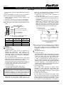
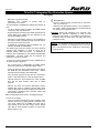
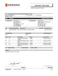
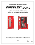
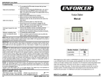
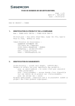
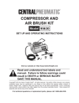
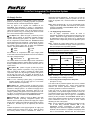
Page 1 of 8
TOTALPAC2 Integrated Fire Protection System
Air Supply
Air Supply Section
Preaction, dry valve and other sprinkler systems using air
pressure for supervisory or releasing purposes are provided
with either internal or external supervised air supplies.
Four (4) styles of air supplies are available for the
TOTALPAC2 units depending on needs or configurations.
These air supplies are all factory assembled, mounted in the
cabinet and pressure tested. They are all located in the top
part of the cabinet, hung on mounting rails above the valve
trim. Here is the description of those options:
Air Option "A": (Refer to Figure 1) Used only for the
sprinkler piping network of electrically operated preaction
systems and with dry pipe systems. Air option "A" includes
the air compressor mounted inside the TOTALPAC2 cabinet
with its supervisory trim and options. Compressors are of the
oiless piston type without reservoir and are factory piped to
the sprinkler piping system riser, all within the TOTALPAC2
cabinet. They are available in four (4) sizes;
1/6HP
1/2HP
1/3HP
1HP.
All the above air compressors have open, single phase
motors with internal thermal protection and can be ordered in
two supply voltages settings:
120Vac-60Hz or
220Vac-50Hz.
The 120Vac-60Hz is the normal voltage used in Canada and
the United-States while the 220Vac-50Hz is primarily used in
Europe, Middle-East and other countries with 220 volts, 50
cycles current.
Air Option "B": (Refer to Figure 2) Used only for the
sprinkler piping network of preaction or dry pipe systems,
when an external air supply is provided by others (either
compressor, plant air or dry nitrogen cylinders) and piped to
the air inlet port of the unit. Air option "B" provides an Air
Pressure Maintenance Device (APMD) trim, factory mounted
in the TOTALPAC2 cabinet.
Note: For the releasing system piping of pneumatically
actuated systems, use air supply type "C" or "D" below
(with an external air compressor).
Air Option "C": (Refer to Figure 3) Used only for the
pneumatic release piping network of pneumatically operated
preaction or deluge systems. An external air supply has to
be provided by others (either compressor, plant air or dry
nitrogen cylinders) and piped to the air inlet port of the unit.
Air option "C" provides an Air Pressure Maintenance Device
(APMD) trim, factory mounted in the TOTALPAC2 cabinet.
Air Option "D": (Refer to Figure 4) Mainly used with
preaction systems protecting refrigerated spaces and
freezers, where a special dry external air supply unit is piped
directly to the system riser inside the freezer itself, as shown
in NFPA-13. Provides only an air supervisory and shut-off
trim.
Ambient temperature at the special external air supply unit
o
o
location should not exceed 104 F (40 C). Refer to NFPA
and Factory Mutual Codes & Standards for details on
refrigerated spaces applications. Air option "D" can also be
used when the contractor prefers to provide his own air
supply & regulation trim, mounted outside the TOTALPAC2
cabinet.
Note: When Air Options "B", "C" or "D" are selected, the air
supply should be provided and installed by the sprinkler
contractor OUTSIDE of the TOTALPAC2 Cabinet It is NOT
provided with the unit.
1. Air supply design and selection:
The air supply compressor should be sized to
automatically establish the total required air pressure in 30
minutes. External air supply should be provided with an
Air Maintenance Device (Air Option "B") to regulate and
restrict the flow of supervisory air into the sprinkler system
piping.
Note: External air supply MUST always be restricted to
insure that the automatic air supply cannot replace air as
fast as it escapes when a sprinkler operates.
WARNING! Pressures other than the factory pressure
settings may affect the operation of the system.
Air Compressor selection Table (Gast):
Format (HP)
Free Air @ 40 psi
(CFM)
Maximum
Gallons in
System to Pump
to 40 psi
in 30 Minutes
1/6
1.0
90
1/3
2.0
180
1/2
3.1
300
1
5.9
600
Note: Selection of the proper air compressor size is the
responsibility of the installing contractor.
2. Connecting the Air Compressor to AC power
(Air option "A" only):
The motor must be protected against short circuit, overload
and excessive temperature rise. Fuses, motor protective
switches and thermal protective switches provide the
necessary protection in these circumstances.
Fuses only serve as a short circuit protection of the motor
(wiring fault), not as protection against overload. Those are
provided and wired by the electrical contractor. An isolation
switch (for location detail, refer to Figure 2 in CONTROLS
Section) is also provided in the TOTALPAC2 Cabinet and is
factory wired, allowing powering off the air compressor while
some maintenance work on the unit is done, without
disturbing the rest of the system.
Note: The air compressor is separately pre-wired to its own
set of field wiring terminals identified TBB in the
TOTALPAC2 controls compartment or junction box,
depending on the enclosure configuration selected. These
terminals must be wired to a separate and properly sized
fuse or circuit breaker, different from the control panel
FM-072G-0-06 G
Page 2 of 8
TOTALPAC2® Integrated Fire Protection System
Air Supply
(when supplied). Observe all applicable codes for wiring of
the unit.
Connect non-energized AC power to the air compressor.
Refer to figure below and FIELD WIRING DIAGRAM.
.1 Connect the wire providing in-coming voltage to the
terminal TBB #6.
.2 Connect the neutral wire to the terminal marked TBB #5.
.3 Connect the ground wire to the terminal marked TBB #4.
Note: TBB #1, 2 & 3 when system is provided without control
panel.
INPUT POWER SOURCE
120Vac, 60Hz
220Vac, 50 Hz
L1
NEUTRAL
1
2
3
4
5
6
GROUND
GROUND
NEUTRAL
L2
TOTALPAC2 CONTROL PANEL
(L1) 1.2A @ 120V - 0.65A @ 220V
Turn clockwise to increase
both cut-out and cut-in
pressure adjustment.
Factory set.
DO NOT CHANGE !
AIR COMPRESSOR
(L2) 1 HP Maximum
FM-072Q-0-109 A
TBB
factory set. This switch should not need any adjustment
but if necessary, follow the instructions below:
.a Remove the metal cover of the compressor air
pressure switch (E2).
.b To raise the cut-out pressure of the air compressor,
turn the cut-out adjustment screw (middle) half a turn
CLOCKWISE.
.c Open the system main drain valve (D3) and let the
pressure drop until the air compressor (E1) restarts.
Check pressure reading on the system pressure
gauge (E3) when the air compressor stops again.
Repeat until the desired pressure is reached. Once all
done, replace the metal cover on the switch (E2).
Wiring size: Minimum 14 AWG with 600V Insulation.
TWO CIRCUITS ARE REQUIRED
Compressor Size
(HP)
1/6
1/3
½
1
Amp. Rating at
120Vac – 60Hz
3,9
5,8
12,0
10,4
Amp. Rating at
220Vac – 50Hz
2,0
2,9
6,0
5,2
3. Operation
Air Option "A":
.1 To Apply Air Supply:
Establish 120Vac power for the air compressor by
activating the correspondent circuit breaker at the
electrical distribution panel.
Start compressor by
activating the compressor isolating switch (E15) located
in the control section of the unit (refer to CONTROLS,
Fig. 1 or 2 for exact location).
If the air compressor motor fails to start or slows down
under load, shut the compressor off. Check that the
supply voltage agrees with the motor nameplate.
A Float Check Valve (E9) is provided with Air Option "A".
The Float Check Valve allows sensing of air pressure in
the system during supervisory times of the system.
.2 To close air supply:
Turn off the compressor isolating switch (E15).
.3 To adjust system air pressure (Furnass switch):
WARNING: The cut-out/cut-in differential switch adjustment
screw (small screw to the right) is factory set. DO NOT
CHANGE ITS SETTING. Any unauthorised modification of
this setscrew adjustment will void the system warranty and
may also prevent the system from operating normally !
The air compressor cut-off pressure switch (E2) (shown
below with its metal cover removed) has its air
compressor cut-out adjustment switch (middle screw)
FM-072G-0-06 G
Front view of the Furnass Switch
(Part # 69HA3)
Note: Do not turn the cut-out adjustment screw (middle) all
the way down in one shot. Proceed by steps. Use the
same method turning the cut-out adjustment screw
COUNTER-CLOCKWISE to lower the air compressor cutout pressure.
Air options "B" or "C":
.4 To Apply Air Supply:
Turn on upstream air supply. Open APMD (Air Pressure
Maintenance Device) input valve (E6) by placing handle
in line with valve body then open APMD output
valve (E7) by placing handle in line with the valve body.
In order to accelerate filling of sprinkler piping by air
pressure, bypass valve (E8) can be opened by placing
handle in line with valve body while piping is initially filled
by the air compressor,. This valve (E8) must then be
closed (handle crossways to valve body) and kept in this
position once the system is filled with air.
.5 To Close Air Supply:
Close APMD output valve (E7) by placing handle
crossways to valve body then close APMD input
valve (E6) by also placing handle crossways to the valve
body. Be sure bypass valve (E8) is closed (handle
crossways to valve body).
.6 To Adjust System Air pressure:
Be sure APMD input valve (E6) and APMD output
valve (E7) are both open (handle in line with the valve
body), and bypass valve (E8) is closed (handle crossways
to valve body) prior to performing this operation. Loosen
lock nut and turn pressure adjustment nut clockwise to
Page 3 of 8
TOTALPAC2 Integrated Fire Protection System
Air Supply
increase air pressure or counter-clockwise to decrease
pressure. Tighten lock nut.
Note: Depending on site conditions, the internal filter of the
APMD may need maintenance on a regular basis. Refer
to Viking Data Sheet # 127a for more details.
Air option "D":
.7 To Apply Air Supply:
Turn on upstream air supply. Open Bypass valve (E8)
by placing handle in line with valve body.
.8 To Close Air Supply:
Close bypass valve (E8) (handle crossways to valve
body).
4. Maintenance and inspection:
Air Option "A":
.1 To close the Air Supply:
This procedure requires turning OFF the air compressor's
AC power by switching off the compressor isolating switch
(E15) located in the control section of the unit before
servicing. Note that the air compressor motor is equipped
with thermal protectors that reset automatically. These
thermal protectors will stop the motor in case it overheats
and can automatically start the motor when they reset.
.2 To remove and clean the check valve assembly (E11):
This procedure requires turning OFF the compressor's
AC power. Follow instructions "To close Air Supply"
above.
.a Carefully loosen the ¼" copper adapter, remove copper
tubing, and proceed to disassemble the check valve
assembly (E11).
.b Once disassembled, carefully clean the check valve
seat, or replace the check valve (part # 40CHSW0002)
altogether if worn out components are found.
.c Remove all brass connections, by unscrewing gently all
tubing adapters from the fittings, removing the
previously installed Teflon tape and apply new Teflon
tape on all threads. Re-install all components and
check for leaks after reconnecting power to the air
compressor.
.3 To clean or replace the compressor's air inlet filter:
This procedure requires turning OFF the compressor's AC
power. Follow instructions "To close Air Supply" above.
.a The motor compressor unit should be kept dirt-free. A
dirty filter restricts air flow, and causes the pump to run
hotter and results in longer operating cycles.
.b To inspect the inlet filter, turn the black plastic cover
counter-clockwise to remove it from its case (refer to
Figure 1). Remove old felt. Clean or replace with new
one (part # B 344 A). DO NOT CLEAN WITH
PETROLEUM-BASED PRODUCTS.
.c Re-install filter and cap.
DO NOT OPERATE
COMPRESSOR WITHOUT A FILTER.
Note:
Refer to the GAST Operation & Maintenance
Technical Manual provided with the TOTALPAC2 unit for
more details.
Intake and exhaust filters are standard on most
compressors and will provide adequate filtration for most
applications. Check filters periodically and replace when
necessary. Initial inspection is suggested at 500 hours,
then the user should determine the frequency. Most
problems can be prevented by keeping filters and mufflers
clean. Dirty filters and mufflers decrease compressor
performance and can decrease compressor service life.
Should the compressor need rebuilding, field rebuilt kits
are available from Gast or its Authorized Service Facilities.
Refer to the compressor's Owner's Manual provided with
the TOTALPAC2 unit. Maintain a clean air filter cartridge to
insure best flow and performance. The location and the
quality of the air being ingested indicates the frequency for
inspection and replacement. A dirty filter restricts air flow,
causes the pump to run hotter and results in longer
operating cycles.
.4 To drain the Air Supply Accumulator:
The amount of moisture pumped into the system and how
quickly it accumulates is proportional to the amount of
humidity in the air and how long the compressor is in
operation.
This unit has been designed to operate
o
between 32 and 100 F.
At least once a year, open air option Drain Valve (E12)
until all condensate water is drained from the air receiver.
Close air option Drain Valve.
Warning ! The relief valve and outlet pipe of the air
compressor may become very hot during normal
operation. Do not touch the valve, compressor heads or
outlet piping until the compressor has been turned off
and allowed to cool.
A safety relief valve is provided on standard compressors
and is preset at the factory. Do not exceed or adjust safety
relief pressures other than those preset at the factory.
Warning ! Do not unscrew relief valve head entirely off
while the compressor is operating. Ejection of valve
parts could cause severe injury.
Air Options "B" or "C":
The Viking Model D-2 Air Pressure Maintenance Device
(APMD) (E5) is a pressure regulator that automatically
reduces the supply air pressure to a pre-set requirement
when connected to a constantly maintained air supply (plant
air, external air compressor or dry nitrogen tank). Refer to
Figure 2 for details.
Features:
- Replaceable air filter
- Outlet pressure range is 5 to 75 psi ( ± 2 psi) (34,47 to
517,11 kPa). Air pressure setting can be readjusted after
installation. See Paragraph 3.6, TO ADJUST SYSTEM
AIR PRESSURE.
FM-072G-0-06 G
Page 4 of 8
TOTALPAC2® Integrated Fire Protection System
Air Supply
- Ball check to prevent back flow.
- Restriction 1/16" (1,59mm) to prevent rapid repressurization of a system.
The Viking Model D-2 APMD (E5) regulates and restricts air
flow.
- The air or nitrogen supply provided to the APMD must be
continuous, clean, dry and oil free.
- By-pass piping is provided to allow initial pressurization of
system piping more rapidly than the restricted air flow
through the APMD will allow.
- Determine the appropriate pressure to be maintained in
the system. Refer to System Data and Technical Data for
the system and components used.
- If adjustment is necessary, refer to paragraph 3.6 TO
ADJUST SYSTEM AIR PRESSURE.
The APMD (E5) should be checked for correct pressure
regulation after installation or repair by noting the air
pressure reading within the system. If adjustment is
required, refer to paragraph 3.6, TO ADJUST SYSTEM AIR
PRESSURE. The filter should also be inspected and
replaced or cleaned as required.
To clean Air Pressure Maintenance Device (APMD) (E5) in
Air option B (refer to Figure 2):
- Do not disconnect or disassemble the APMD without
closing the outlet (E7) and inlet (E6) isolation valves.
- System air pressure will be trapped between the outlet of
the APMD and the downstream control valve. Relieve
pressure before proceeding with disassembly.
- This procedure requires turning OFF the compressor's
power. Follow instructions "To close Air Supply" above.
- Carefully loosen the union between the outlet of APMD
(E5) and the outlet isolation valve (E7) to relieve
pressure.
- Remove and clean Air Pressure Maintenance Device
(APMD) filter. Refer to VIKING Technical Data Sheet
127a & b Model D-2 Air Pressure Maintenance Device for
more details. If admission filter is blocked, replace with
filter kit (part # 03007 A).
Refer to Viking Data Sheet 127a & b for additional details.
To close the Air Supply:
Close Air Pressure Maintenance Device (APMD) output
isolation valve (E7) by placing handle crossways to the
valve body. Make sure the APMD input valve (E6) is
open (handle in line with valve body), and the bypass
valve (E8) is closed (handle crossways to valve body).
Refer to Figure 2 or 3.
FM-072G-0-06 G
Air option "D":
- The air or nitrogen supply provided must be continuous,
clean, dry and oil free.
- Determine the appropriate pressure to be maintained in
the system. Refer to System Data and Technical Data for
the system and components used.
Important: Advise local authorities of the necessary work
over the fire protection equipment. In order to avoid
accidental water release, it is considered good practice to
completely close the main water inlet valve while doing
maintenance work.
Warning! Air compressor head and copper tubing may be
relatively hot after the air compressor has run for some
time. Take precautions when handling the components to
avoid skin burns.
Page 5 of 8
TOTALPAC2 Integrated Fire Protection System
Air Supply
Figure 1 – Air Option "A"
(Cabinet mounted air compressor)
Air Option Components:
E1
E2
E3
E4
E5
E6
E7
E8
E9
E10
Air compressor
Air compressor "ON/OFF" pressure switch
System air pressure gauge
Air supervisory pressure switch
N/A
N/A
N/A
N/A
Float check valve
Soft-seat check valve
E11
E12
E13
E14
E15
Air compressor check valve
Air option drain valve
N/A
N/A
Compressor isolating switch (not shown)
Optional Components:
(see Air Supply Options for details)
-
Viking Dehydrator
Accelerator
FM-072G-0-06 G
Page 6 of 8
TOTALPAC2® Integrated Fire Protection System
Air Supply
Figure 2 – Air Option "B"
(APMD without air compressor)
Note: The external air supply must be restricted to insure that it cannot replace air as fast as it escapes when a releasing device or
sprinkler operates. When the system is put in service, open the input valve (E6) first.
Air Option Components:
E1
E2
E3
E4
E5
E6
E7
E8
E9
E10
N/A
N/A
System air pressure gauge
Air supervisory pressure switch
Air pressure maintenance device (APMD)
APMD input valve
APMD output valve
APMD bypass valve
N/A
N/A
E11
E12
E13
E14
E15
E16
Optional Components:
(see Air Supply Options for details)
-
FM-072G-0-06 G
N/A
N/A
N/A
N/A
N/A
Swing check valve
Viking Dehydrator
Accelerator
Page 7 of 8
TOTALPAC2 Integrated Fire Protection System
Air Supply
Figure 3 – Air Option "C"
(APMD for Pilot Line release system only)
Note: The external air supply must be restricted to insure that it cannot replace air as fast as it escapes when a releasing device or
sprinkler operates. When the system is put in service, open the input valve (E6) first.
Air Option Components:
E1
E2
E3
E4
E5
E6
E7
N/A
N/A
System air pressure gauge
Air supervisory pressure switch
Air pressure maintenance device (APMD)
APMD input valve
APMD output valve
Optional Components:
(see Air Supply Options for details)
-
Accelerator
FM-072G-0-06 G
Page 8 of 8
TOTALPAC2® Integrated Fire Protection System
Air Supply
Figure 4 – Air Option "D"
(Air supply connection only for external air supply )
Note:
The external air supply must be restricted to insure that it cannot replace air as fast as it escapes when a releasing device
or sprinkler operates.
Air Option Components:
E1
E2
E3
E4
E5
E6
E7
E8
E9
E10
N/A
N/A
System air pressure gauge
Air supervisory pressure switch
N/A
N/A
N/A
N/A
N/A
Soft-seat check valve
FM-072G-0-06 G
E11
E12
E13
E14
N/A
N/A
N/A
Air shut-off valve
Optional Components:
(see Air Supply Options for details)
-
Viking Dehydrator
Accelerator