1
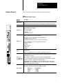
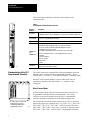
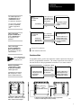
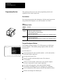
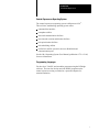
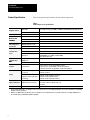
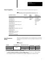
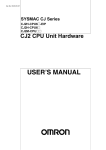
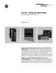
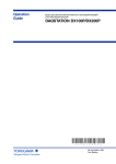
1771 Control Coprocessor (Cat. No. 1771-DMC, -DMC1, -DMC4, and -DXPS) Product Data Complement your PLCR ladder programming. You can write control coprocessor programs in BASIC, C, or assembler languages. These user programs run asynchronously to and independently of the PLC control logic, but they have access to its memory. You can use PLC control-logic programs to start and stop your C, BASIC, or assembler programs. Add only the functionality that you need. You can configure the control coprocessor as either a 1-slot (main) or 2-slot (main and serial expander) module. Versions of the main module are: Control Coprocessor Main Module Selection Catalog Number 256 Kbytes 1771DMC 1 Mbyte with Ethernet R 1771DMC1 4 Mbytes with Ethernet 1771DMC4 See Table 6 on page 9 for more information on memory usage. Product Data 1771 Control Coprocessor You can also install additional RAM memory in your main module. You can use the serial expander module (1771-DXPS) with any version of the main module. This module provides additional serial ports and an ASCII display. This partitioning of functionality ensures that you are not burdened with costs where you do not need features. The control coprocessor is simple to install. The control coprocessor resides in the same 1771 Universal I/O chassis as the PLC programmable controller, or adapter module, and I/O modules. All communication ports have standard pin assignments and can use “off-the-shelf” cables. Allen-Bradley offers one-stop shopping. In addition to the main and serial expander modules, Allen-Bradley offers several types of Ethernet cables and transceivers as well as a Program Development Software package. Benefits The control coprocessor expands the capability of a PLC programmablecontroller system by running C, BASIC, and assembler programs that perform tasks such as: storing, analyzing, and manipulating input, output, and other information gathered from the PLC programmable controller communicating with devices external to the PLC programmablecontroller system via the Ethernet port or the asynchronous serial communication port(s) You can use the control coprocessor for applications such as: complex math or application-specific algorithm calculation using C and/or BASIC programs production scheduling or historical-data logging/tracking high-speed search and compare of very large files or look-up tables protocol conversion for interfacing a PLC programmable controller with a variety of field devices 2 Product Data 1771 Control Coprocessor Hardware Overview Table 1 describes the hardware elements for the main module. Table 1 MainModule Hardware Elements Hardware Element RESET Switch LEDs Description Use the reset switch to reinitialize the control coprocessor When the serial expander module is installed, use the keyswitch to reinitialize the coprocessor Four status indicators provide information on the CPU, COMM0 port, COMM1 port, and battery This is a 9pin, optically isolated, serial communication port that supports communication defined by EIA RS232C standards COMM0 Port Use this port to connect: • personal computers • terminals • other peripheral devices This is a 25pin, optically isolated, serial communication port that supports communication defined by EIA RS232C, 423, and 485 standards You can also use this port with most RS422A equipment as long as: • termination resistors are not used • the distance and transmission rate are reduced to 200 ft at 19.2 kbps COMM1 Port Battery Use this communication port to connect peripheral devices such as: • personal computers • terminals • barcode readers • weigh scales • printers This battery provides backup power for control coprocessor memory during power failure or normal down time Use the 3.0 volt lithium battery (1770XYC) that is provided with your coprocessor The 1771DMC1 and 1771DMC4 versions of the control coprocessor include an Ethernet communication port that connects to thickwire, thinwire, or twistedpair networks via a standard 15pin transceiver connection Ethernet Port (1771DMC1 and 1771DMC4 only) These modules use TCP/IP protocol and have resident FTP and TELNET utilities You can program client/server applications for an Ethernet port using the TCP/IP socket library; an Internet socket library is supplied with the PCBridge software A downloadable driver is also availableas a part of the PCBridge softwarethat provides INTERCHANGEt server functionality; when the coprocessor is attached to a standard PLC5 processor, this provides Ethernet connectivity 19397 You can install additional RAM in the main module to expand user memory The following single inline memory modules (SIMMs) are available: Optional RAM Memory Size Catalog Number 256 Kbytes 1 Mbyte 4 Mbytes 1771DRS 1771DRS1 1771DRS4 3 Product Data 1771 Control Coprocessor Table 2 describes the hardware elements for the optional serial expander module. Table 2 Serial Expander Module Hardware Elements Hardware Element Keyswitch Description This is a 2position, springloaded keyswitch The RESET position is used to reinitialize the control coprocessor without cycling power ASCII Display The 4character alphanumeric display shows information on the state of the control coprocessor, as provided by user programs LEDs The two status indicators provide information on the COMM2 and COMM3 ports These are 25pin, optically isolated, serial communication ports that support communication defined by EIA RS232C, 423, and 485 standards COMM2 Port and COMM3 Port Fault Relay 19397 Communication with a PLC Programmable Controller You can also use the port with most RS422A equipment as long as: • termination resistors are not used • the distance and transmission rate are reduced to 200 ft at 19.2 kbps Use these communication ports to connect peripheral devices such as: • terminals • personal computers • barcode readers • weigh scales • printers The relay contact switches on a detected mainmodule hardware fault; the relay will handle 500 mA at 30 Vac/dc (resistive) The control coprocessor communicates with a programmable controller through a direct connection to the programmable controller—directconnect mode—or via the 1771 I/O chassis backplane—standalone mode. When the serial expander module is used in either mode, place it immediately adjacent to the main module—i.e., under the same locking tab. DirectConnect Mode In direct-connect mode, either the control coprocessor or the PLC-5 programmable controller initiates communications. The control coprocessor can read from and write to the PLC-5 programmablecontroller data table asynchronously to the ladder-program scan. A control coprocessor and serial expander in directconnect communication with a PLC5 programmable controller 4 19398 You can directly connect the control coprocessor to a PLC-5 processor that has the coprocessor expansion port—e.g., a PLC-5/11t, PLC-5/20t, PLC-5/20Et, PLC-5/30t, PLC-5/40t (series B, revision B or later), PLC-5/40Et, PLC-5/40Lt, PLC-5/60t (series B, revision B or later), PLC-5/60Lt, PLC-5/80t, or PLC-5/80Et programmable controller. Product Data 1771 Control Coprocessor The control coprocessor can initiate directaccess communication to PLC5 user memory as shown here. You do not need to program your PLC5 programmable controller to support these calls. A PLC5 controllogic program can initiate direct access communication to the control processor as shown here. A PLC5 controllogic program can initiate back plane communication with the control processor in direct connect mode via: Tip We recommend that you use 1slot addressing for standalone mode. Only the programmable controller initiates commu nication with a standalone control coprocessor. Communication is via the back plane using discrete or block transfer read/write instructions. Discrete or Block Transfer Read/Write Communicates, in the same chassis, with a PLC5 or mini PLC2R program mable controller via the backplane PLC5 Programmable Controller Control coprocessor can read/write PLC5 datatable and status file information User Memory PLC5 Programmable Controller Controllogic program using MSG instruction PLC5 controllogic program (MSG) initiates communication Control Coprocessor PLC5 interface routines called in a C or BASIC program Control Coprocessor Interface routines in C or BASIC program accept, interpret, and respond to PLC5 programmable controller discrete I/O read/write block-transfer read/write Standalone Mode In standalone mode, you do not connect the control coprocessor directly to the PLC programmable controller. The control coprocessor can reside in the same chassis as the programmable controller or in a remote chassis. Programmable controller Programmable Controller controllogic program initiates communication using discrete and/or Controllogic program blocktransfer read and using discrete and/or write instructions blocktransfer instructions PLC5, PLC5/250t, PLC3R, or PLC2R programmable controller Control Coprocessor Interface routines in C or BASIC program accept, interpret, and respond to programmable controller Remote I/O Link Communicates, from a remote chassis, with the programmable controller via an I/O adapter module (1771ASB) 19400 5 Product Data 1771 Control Coprocessor Programming Overview This section provides an overview of the programming interface and capabilities of the control coprocessor. User Interface You can develop programs and communicate with the control coprocessor using a DOS-based computer or an ASCII terminal. See Table 3. Table 3 Programming Terminals With this device: You can: DOSbased computer • • • • • ASCII terminal • develop BASIC programs • perform program debugging • initiate and terminate tasks using the OS9 operating system commandline interface initialize and configure the control coprocessor initialize and configure the Ethernet port develop C, BASIC, and assembler programs perform program debugging initiate and terminate tasks using the OS9 operating system commandline interface ProgramDevelopment Software The PCBridge software package (1771-PCB) operates on a DOS-based personal computer. This software package supports offline and online user activities. Use this software to: download/upload files and executable modules—or files and modules— to/from the control coprocessor develop and edit source files compile, assemble, and link multiple source files written in C or assembler emulate an ASCII terminal, which allows your personal computer to act as a console device to the control coprocessor use various online programs, such as basic (BASIC language environment) and SrcDbg (source-level debugger for C programs) access configuration (offline options) and other miscellaneous utilities initialize and configure the Ethernet port 6 Product Data 1771 Control Coprocessor ControlCoprocessor Operating System The control-coprocessor operating system is Microware OS-9. This real-time, multitasking operating system offers: command-line interface semaphore utilities inter-task communication facilities run-time task creation and deletion facilities task-prioritization facilities task-scheduling utilities unified I/O and file system for access to RAM disk and communication ports See the OS-9 Operating System User Manual, publication 1771-6.5.102, for more information. Programming Languages You develop C, BASIC, and assembler programs using the PCBridge software. You can also develop and edit BASIC programs on the control coprocessor using a terminal or a personal computer for terminal emulation. 7 Product Data 1771 Control Coprocessor Product Specifications Table 4 lists general specifications for the control coprocessor. Table 4 ControlCoprocessor Specifications Backplane Current Fault Relay Environmental E i t l Conditions Time of Day Clock TimeofDay and Calender Communication Ports② • 2.50 Amps at +5 Vdc (1771DMC module with no Ethernet) • 4.00 Amps at +5 Vdc (1771DMC1 or DMC4 module with Ethernet and transceiver)① Serial expander module 1.5 Amps at +5 Vdc Serial expander module 500 mA at 30 Vac/dc (resistive) Operating temperature 0-60° C (32-140° F) Storage temperature 40-85° C (40-185° F) Relative humidity 5-95% (without condensation) Maximum variations at 60° C ±5 minutes per month Typical variations at 20° C ±20 seconds per month COMM0 RS232C; 9pin COMM1, COMM2, and COMM3 RS232C, 423, 485, and 422A compatible; 25pin Ethernet port TCP/IP protocol using FTP, TELNET, and socket library routines; INTERCHANGE server, SNMP compatible (MIB I); 15pin standard transceiver COMM0, COMM1, COMM2, and COMM3 ports 110, 150, 300, 600, 1200, 2400, 4800, and 9600 bps, 19.2 Kbps, and 38.4 Kbps Ethernet 10 Mbps 1771I/O chassis • directconnect to a PLC5 programmable controller • same chassis as a programmable controller, but standalone • remotely located from a programmable controller and standalone Main module (on the upper C connector) • between 24 and 26 • between 30 and 32 Keying Serial expander module (one on the upper C and two on the lower D connectors) • between 16 and 18 (upper C connector) • between 2 and 4 (lower D connector) • between 16 and 18 (lower D connector) Agency Certification (Only when product is marked) • CSA certified • CSA Class I, Division 2, Groups A, B, C, D • UL listed Battery Life Main module 1 year Communication Rates Location 8 Main module ① This is an approximate value. See Chapter 2 of the 1771 Control Coprocessor User Manual, publication 17716.5.95, for instructions on calculating backplane current requirements. ② With the 1771DMC module (256 Kbytes), DF1 is not available on the communication ports; if you add an optional 1 or 4Mbyte SIMM, however, the communication ports will initialize with DF1 capability. Product Data 1771 Control Coprocessor Product Compatibility Table 5 lists products compatible with the control coprocessor. Table 5 Other AllenBradley Products Compatible with the Control Coprocessor Programmable Controllers I/O Chassis Adapter Modules Terminals or Personal Computers DirectConnect Mode • PLC5/11 processor • PLC5/20 processor • PLC5/20E processor • PLC5/30 processor • PLC5/40 (series B, revision B or later) processor • PLC5/40E processor • PLC5/40L processor • PLC5/60 (series B, revision B or later) processor • PLC5/60L processor • PLC5/80 processor • PLC5/80E processor Any Universal 1771 I/O chassis Any 1771ASB adapter module in a remote chassis Terminals: • VT220 (DEC) • other ASCII terminal Personal Computers: • IBMR PC/AT • T47 • T50 • T53 • T60 Standalone Mode in a programmablecontroller chassis • any PLC5 processor • mini PLC2 processor Standalone Mode in a remote chassis • any PLC5, PLC5/250 processor • PLC3 processor • PLC2 processor (remote I/O only) ControlCoprocessor Memory Table 6 shows RAM configuration. You can configure the free user portion of RAM for your requirements. You can also change the default size of the TAG table. Table 6 RAM Configuration Total RAM Default RAMDisk Size 256 Kbytes (1771DMC)③ 1 Mbyte (1771DMC1) 4 Mbytes (1771DMC4) 64 Kbytes y RAM Required by the System Default TAG Table① Free User RAM② 120 Kbytes 0 72 Kbytes 215 Kbytes 80 Kbytes 665 Kbytes 215 Kbytes 80 Kbytes 3737 Kbytes ① To change the default size of the TAG table, see the section in Chapter 3 of the 1771 Control Coprocessor User Manual, publication 17716.5.95, on configuring the control coprocessor (CC_CFG utility). ② To configure the control coprocessor RAM free user memory, see Chapter 3 of the 1771 Control Coprocessor User Manual, publication 17716.5.95, on configuring the controlcoprocessor system memory (MEM_CFG utility). ③ Source debugging for C programs does not work with this memory configuration. Debugging requires a minimum of 512 Kbytes. 9 Product Data 1771 Control Coprocessor Table 7 lists the optional RAM single inline memory modules (SIMMs) that you can add to your control coprocessor. Table 7 Additional RAM MemoryOptional① Memory Size Catalog Number 256 Kbytes 1771DRS 1 Mbyte 1771DRS1 4 Mbytes 1771DRS4 ① These optional RAM SIMMS are not the same as those used in generic personal computers, which are dynamic RAM. The 1771DRS RAM SIMMS are special static RAM chips. CSA Certification CSA certifies products for general use as well as for use in hazardous locations. Actual CSA certification is indicated by the product label. See the CSA Hazardous Location Approval Supplemental Product Information, publication ICCG-4.1, for more information. UL Certification Underwriters Laboratories Inc. (UL) performs safety investigations of electrical and electronic equipment and products as well as other equipment and products. After product samples have been safety tested and are found to comply with applicable safety requirements, UL authorizes a manufacturer to apply the appropriate UL Mark on products that continue to comply with the requirements. In the case of Allen-Bradley’s control coprocessor, it is the presence of the UL Listing Mark on the individual product that indicates UL certification. Ethernet is a trademark of Intel Corporation, Xerox Corporation, and Digital Equipment Corporation. IBM is a registered trademark of International Business Machines Corporation. OS-9 is trademark of Microware Systems Corporation. PLC, PLC-2, PLC-3, and PLC-5 are registered trademarks of Allen-Bradley Company, Inc. INTERCHANGE, PLC-5/11, PLC-5/20, PLC-5/20E, PLC-5/30, PLC-5/40, PLC-5/40E, PLC-5/40L, PLC-5/60, PLC-5/60L, PLC-5/80, PLC-5/80E, and PLC-5/250 are trademarks of Allen-Bradley Company, Inc. AllenBradley has been helping its customers improve productivity and quality for 90 years. AB designs, manufactures and supports a broad range of control and automation products worldwide. They include logic processors, power and motion control devices, manmachine interfaces and sensors. AllenBradley is a subsidiary of Rockwell International, one of the world's leading technology companies. With major offices worldwide. Algeria • Argentina • Australia • Austria • Bahrain • Belgium • Brazil • Bulgaria • Canada • Chile • China, PRC • Colombia • Costa Rica • Croatia • Cyprus • Czech Republic Denmark • Ecuador • Egypt • El Salvador • Finland • France • Germany • Greece • Guatemala • Honduras • Hong Kong • Hungary • Iceland • India • Indonesia • Israel • Italy Jamaica • Japan • Jordan • Korea • Kuwait • Lebanon • Malaysia • Mexico • New Zealand • Norway • Oman • Pakistan • Peru • Philippines • Poland • Portugal • Puerto Rico Qatar • Romania • Russia-CIS • Saudi Arabia • Singapore • Slovakia • Slovenia • South Africa, Republic • Spain • Switzerland • Taiwan • Thailand • The Netherlands • Turkey United Arab Emirates • United Kingdom • United States • Uruguay • Venezuela • Yugoslavia AllenBradley Headquarters, 1201 South Second Street, Milwaukee, WI 53204 USA, Tel: (1) 414 3822000 Fax: (1) 414 3824444 Publication 17712.216December 1994 Supersedes 17712.216September 1992 10 PN 95511924 Copyright 1994 AllenBradley Company, Inc. Printed in USA