1
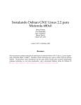
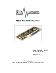
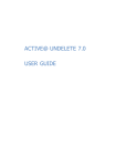
Digital
BroadCaster™
User’s Manual
Hardware, Software and Manual
by
Digital Micronics, Inc.
2075 Corte Del Nogal, Unit N
Carlsbad, CA 92009
December 6, 1993
First Printing
DIGITAL BROADCASTER™ USER’S MANUAL
DECEMBER 6, 1993: FIRST PRINTING
COPYRIGHTS
Copyright © 1993 Digital Micronics, Inc. All Rights Reserved.
The Digital BroadCaster, and DMI 601 are Copyright © 1993 Digital Micronics, Inc. All rights reserved. This
document may not in whole or in any part, be copied, photocopied, reproduced, translated, or reduced to any
electronic medium or machine readable format without prior consent, in writing from Digital Micronics, Inc.
TRADEMARKS
Digital BroadCaster, DMI 601 and Edimation are trademarks of Digital Micronics, Inc. Kickstart and
Workbench are trademarks and Amiga is a registered trademark of Commodore-Amiga, Inc. Other marks are
trademarks of their respective holders.
DISCLAIMER
DIGITAL MICRONICS, INC. (DMI) MAKES NO WARRANTIES, EITHER EXPRESSED OR IMPLIED,
WITH RESPECT TO THE PROGRAM OR HARDWARE DESCRIBED HEREIN, ITS QUALITY,
PERFORMANCE, MERCHANTABILITY, AVAILABILITY, OR FITNESS FOR ANY PARTICULAR
PURPOSE. THIS PRODUCT IS SOLD “AS IS.” THE ENTIRE RISK AS TO ITS QUALITY AND
PERFORMANCE IS WITH THE BUYER. SHOULD THE PROGRAM OR HARDWARE PROVE
DEFECTIVE FOLLOWING ITS PURCHASE, THE BUYER (AND NOT DMI, THEIR DISTRIBUTORS OR
THEIR RETAILERS) ASSUMES THE ENTIRE COST OF ALL NECESSARY REPAIR, CORRECTION, OR
SERVICING. IN NO EVENT WILL DMI BE LIABLE FOR DIRECT, INDIRECT, INCIDENTAL OR
CONSEQUENTIAL DAMAGE, OR DAMAGE RESULTING FROM LOSS OF USE OR LOSS OF
ANTICIPATED PROFITS RESULTING FROM ANY DEFECT IN THE PROGRAM OR WITH THE
HARDWARE EVEN IF IT HAS BEEN ADVISED OF THE POSSIBILITY OF SUCH DAMAGE
FCC NOTICE
This equipment has been found to comply with the limits for a Class A digital device, pursuant to Part IS of the
FCC Rules. These limits are designed to provide reasonable protection against harmful interference when the
equipment is operated in a commercial environment This equipment generates, uses, and can radiate radio
frequency energy and, if not installed and used in accordance with the instruction manual, may cause harmful
interference to radio communications. Operation of this equipment in a residential area is likely to cause
harmful interference in which case the user will be required to correct the interference at his or her own
expense.
Table of Contents
1.
The World of Digital Video
2.
Concepts
2.1 Brief Description: How the Digital Broadcaster™ Works . . . . . . 2-1
2.2 Benefits of the Digital Broadcaster™. . . . . . . . . . . . . . 2-3
3.
Installation
3.1
3.2
3.3
3.4
3.5
4.
Digital Broadcaster™ Components . . . . .
Hardware Requirements . . . . . . . . .
Installation of Digital Broadcaster™ Hardware .
Hard Drives and Controllers. . . . . . . .
Software Installation. . . . . . . . . . .
.
.
.
.
.
.
.
.
.
.
.
.
.
.
.
.
.
.
.
.
.
.
.
.
.
.
.
.
.
.
.
.
.
.
.
.
.
.
.
.
3-1
3-1
3-1
3-4
3-9
Recording
4.1
4.2
4.3
4.4
Settings . . .
Time & Storage
Control . . . .
Audio . . . .
.
.
.
.
.
.
.
.
.
.
.
.
5.
EDImation™
6.
Non-Linear Editing
6.1
6.2
6.3
6.4
7.
.
.
.
.
.
Project Menu . .
Active Clip Region
Zoom Edit Area .
Scope/Control Area
.
.
.
.
.
.
.
.
.
.
.
.
.
.
.
.
.
.
.
.
.
.
.
.
.
.
.
.
.
.
.
.
.
.
.
.
.
.
.
.
.
.
.
.
.
.
.
.
.
.
.
.
.
.
.
.
.
.
.
.
.
.
.
.
.
.
.
.
.
.
.
.
.
.
.
.
.
.
.
.
4-2
4-4
4-5
4-7
.
.
.
.
.
.
.
.
.
.
.
.
.
.
.
.
.
.
.
.
.
.
.
.
.
.
.
.
.
.
.
.
.
.
.
.
.
.
.
.
.
.
.
.
.
.
.
.
.
.
.
.
.
.
.
.
.
.
.
.
.
.
.
.
.
.
.
.
.
.
.
.
6-1
6-4
6-5
6-9
Off-Line Transitions
Table of Contents
1
8.
Common Questions and Answers
9.
Troubleshooting Guide
2
Copyright © 1993 Digital Micronics, Inc. Unauthorized Duplication Prohibited
Chapter 1
The World of Digital Video
You are about to embark on a fascinating trip into the world of digital video.
Your purchase of the Digital Broadcaster™ video board and its accompanying
DMI 601™ editing software is your first step on a journey that will ease the
burden of video production and allow your creative abilities to shine.
In the world of digital video, your analog footage is converted to digital data
in a process called digitization. This digital information is then stored in some
storage device such as a floppy disk, or a hard drive. Later, that information can
be retrieved and converted back into analog video for display. This simple
conversion opens up an entirely new world and presents endless new
possibilities to speed video manipulation and add creative options to your video.
The primary advantage of digital video is that the digital data can be placed
on a device which allows almost instantaneous access to any point within the
video. Instead of long fast-forward or rewind delays, you can access any point in
the video at will. Taking this concept further, you can access any point in the
video during playback. This means that you can construct an edit decision list
(EDL) that can access your original video and play back in real time. Your
editing decisions become reality in seconds instead of hours because there is no
need to re-record your video from an EDL.
Also, because the video is now present in a digital form available to a
computer, you can process that data as you would any other digital data. This
opens up creative possibilities that are limited only by your imagination and the
speed of your computer. Some examples of these creative opportunities are:
• Rotoscoping
• Assemble computer rendered or hand drawn images into video
• Off line transitions and special effects.
You have made a wise choice to enter the world of digital video riding the
wave that is the Digital Broadcaster™.
Chapter 1
1-1
Chapter 2
Concepts
The Digital Broadcaster™ is a fine example of recent developments in the
rapidly growing field of digital video and its applications. This chapter is devoted
to informing the user about the functionality of the Digital Broadcaster™ and
how its design leads to its numerous benefits.
2.1
Brief Description: How the Digital Broadcaster™ Works
The Digital Broadcaster™ is similar in function to a video tape recorder
(VTR). However, it records and plays back video to and from a disk drive, rather
than a tape. Use of a disk drive allows features of which VTR designers and
users can only dream.
2.1.1
RECORDING - DIGITIZING VIDEO
The Digital Broadcaster™ accepts a composite, S-Video, component, or
RGB analog video signal and converts it to digital video (a process known as
digitization). This is necessary since the video is saved to a disk drive, which
stores only digital data.
The CCIR 601 standard determines the method for converting the analog
video input to digital data to ensure the video quality. Using this standard, each
second of video data requires over 30 MB (MegaBytes) of digital storage.
Unfortunately, storage devices that can transfer 30 MB of data per second are
few, far between and extremely expensive. Obviously these devices are not
practical in a real-world application.
Dilemma: Since no such devices exist, how can the Digital Broadcaster™
claim to digitize video to a disk drive?
The answer. JPEG Compression
Chapter 2
2-1
2.1.2
JPEG COMPRESSION
JPEG is a compression algorithm for still images. Named after the Joint
Photographic Experts Group who developed the algorithm, JPEG encodes pixel
information for a still image into a new data format (JPEG data) that takes up
considerably less space. The Digital Broadcaster™ uses JPEG for the
following reasons:
1. Obviously, a slower data rate is required for video to be stored to disk.
By compressing digitized video, say 10 times, with JPEG the 30 MB/sec rate
becomes 3.0 MB/sec, a rate that many high-speed hard drives can handle.
2. The microchips used to do the JPEG compression on this product can
do the compression in real-time. Other compression algorithms can compress
data even further, but must be done off-line in non-real-time.
3. JPEG compresses still images so that each frame, even each field, of
video can be uniquely defined by a set of JPEG data.
4. JPEG compression is user-definable. With the Digital Broadcaster™,
the user can choose a compression ratio from 1/6th (6:1) to 1/80th (80:1) the
original size of an image, varying the amount of data representing each frame.
5. The JPEG standard is widely accepted and used in many software
packages, making your recordings compatible with droves of software.
The Digital Broadcaster™ compresses the digitized input data and stores
each compressed field of video sequentially to disk, along with reference
information for each field. This allows for random access of each field during
playback.
2.1.3
QUALITY SETTING CONSIDERATIONS
There is one very important caveat to JPEG that the user must bear in mind.
The settings provided with the Digital Broadcaster™ software allow user control
of the QUALITY of the image. Once set, the quality will remain constant.
However, the size of the compressed images WILL VARY from image to image
and scene to scene. This means that the quality level can be relied upon, but
not the compression or data rate. For this reason, no absolute correlation
between compression ratios, data rates, and storage requirements for a given
quality setting is given.
As an example, during one test, a scene of seals at play in the water was
recorded at VHS quality. Near the end of the recording, the scene changed to
2-2
Copyright © 1993 Digital Micronics, Inc. Unauthorized Duplication Prohibited
some birds in a
group of trees. The size of an extracted frame from the scene of the seals was
about 70 KB for a compression ratio of about 14:1 (2.1 MB/sec). A frame
extracted from the bird scene was over 125 KB for a compression ratio of 8:1
(3.8 MB/sec). The particular hard drive in use had a maximum transfer of 3.5
MB/sec. The result was a loss of frames in the second scene because the hard
drive could not keep up with the data rate from the second scene.
Therefore, we highly recommend that the video to be recorded be previewed
for the most detailed shots. Test that those scenes will record at the chosen
quality on the hard drive in use. This will ensure that the entire reel of video
footage will be successfully captured.
2.1.4
PLAYBACK - DECOMPRESSION
Having explained digitizing data and JPEG compression, playback is simple
to explain: It is the reverse process of recording. During playback, the Digital
Broadcaster™ retrieves JPEG data from disk, decompresses the data into
digitized pixel data which is converted to analog video.
2.2
Benefits of the Digital Broadcaster™
Storing high quality video frames to disk as separate entities in a
widely-accepted standard will allow three substantial features to flourish,
non-linear editing, playing animations without need for a single-frame VTR, and
broadcast quality transmission from a disk drive.
2.2.1.
NON-LINEAR EDITING
Any editor will verify that linear editing takes much time and effort. Most of
that time is spent searching a video tape for the desired cut marks. With video
stored to disk, access to any frame is almost instantaneous. This allows for
non-linear editing, and shorter editing sessions.
2.2.2.
PLAYING ANIMATIONS - NO SINGLE-FRAME VTR REQUIRED
Computer animators can attest to the importance of a single-frame VTR.
Animations must be recorded to tape frame-by-frame, a very time-consuming
process. The Digital Broadcaster™ eliminates the need for the single-frame
VTR. Animators can JPEG each frame of their animations with many available
software packages and then concatenate their frames into a complete animation.
This can then be played by the Digital Broadcaster™ in real time.
Chapter 2
2-3
2.2.3.
BROADCAST QUALITY TRANSMISSION FROM A DISK DRIVE
Providing broadcast quality video from the hard disk is where Digital
Micronics, Inc. has focused most of their energy in development of this product.
The hardware and software have been optimized to allow for maximum data
throughput, allowing JPEG compressions as low as 6:1, which is
indistinguishable from the original. Even the most demanding professionals will
be overwhelmed with the quality that can be output by the Digital
Broadcaster™.
2-4
Copyright © 1993 Digital Micronics, Inc. Unauthorized Duplication Prohibited
Chapter 3
Installation
Installation is a complicated process and should only be attempted by
an authorized dealer or someone well acquainted with the Amiga platform.
3.1
Digital Broadcaster™ Components
•
•
•
•
3.2
Digital Broadcaster™ Expansion Card
Breakout Box
Shielded Ribbon Cable
DBC32™ Install Disk
Hardware Requirements
• Computer: Amiga 3000, Amiga 3000 Tower, or Amiga 4000
CPU: 68030 or 68040
RAM: 4 Megs Fast (8 Megs recommended)
HD & controller: See below
Super Buster Rev. 11 (for A4000 or using FASTLANE on A3000(T))
• Computer monitor compatible with the above Amiga computers
• Second monitor for viewing video capable of displaying PAL or NTSC
video interlaced with composite, S-Video, component, and/or RGB input.
3.3
Installation of Digital Broadcaster Hardware
3.3.1
REMOVING THE COVER
3.3.1.1 Amiga 3000 Users
To remove the cover of the Amiga 3000, remove the 5 screws, 1 located at
Chapter 3
3-1
Figure 3.1 - A3000 and A3000T Disassembly
the center in the back and 2 on the lower part of both sides of the main unit (see
Figure 3.1). With the computer lacing forward, grasp the cover on both sides
and slide it forward.
3.3.1.2 Amiga 3000T Users
To remove the cover of the Amiga 3000T (the side panel on the left), remove
the front panel and then take out the two screws in the front and the two screws
in the back that hold the side panel (see Figure 3.1). Firmly pull out the bottom
of the left side panel and remove it.
3.3.1.3 Amiga 4000 Users
To remove the cover of the Amiga 4000, take out the two screws located in
the upper, rear corners of the main unit. Grasp the cover on both sides and slide
it backwards and up (see Figure 3.2).
3.3.2
3-2
INSTALLATION OF THE DIGITAL BROADCASTER
Copyright © 1993 Digital Micronics, Inc. Unauthorized Duplication Prohibited
The cover plates are
located inside the main unit
ot the computer as shown
in Figures 3.3 and 3.4.
With a Phillips-head screw
driver, remove the cover
plate that corresponds to
the slot in which the
Digital Broadcaster™ will
be installed. Save the
screw for use in installing
the expansion card. Slide
the Digital Broadcaster™
Figure 3.2 - A4000 Disassembly
Figure 3.3 - A3000 and A4000
Expansion Card Installation
card into the slot chosen, allowing the track to
guide the card. To insure complete contact
between the expansion card and the main unit,
push the card until its connector is completely
embedded in the connector of the main unit.
Refer to the computer’s manual or the
manual for any other expansion card installed
in the system for more information on
compatibility (especially with regards to bridge
boards).
Figure 3.5 - A3000T Expansion Card
Installation
Chapter 3
3-3
3.3.3
CONNECTING DIGITAL BROADCASTER™ TO THE BREAKOUT BOX
To connect the Digital Broadcaster™ card and the breakout box, attach
one end of the shielded ribbon cable to the Digital Broadcaster™ card
connector located in the cover plate opening. Note that the cable has a single
screw on each side of each connector which holds the cable to the screw inserts
on the open connector of the Digital Broadcaster™ card and breakout box.
Align one end with the Digital Broadcaster™ card, matching the screw with
exposed threads with the smooth insert and vice-versa. Ensure that both screws
are tightened simultaneously since screwing in one side at a time will result in a
crooked alignment and an incomplete connection. Attach the other end of the
ribbon cable to the breakout box connector in the same manner.
3.4
Hard Drives and Controllers
3.4.1
AMIGA 3000 AND AMIGA 3000T USERS
3.4.1.1 Controller
There are two options available for a hard disk controller
Option 1
The Amiga 3000 and Amiga 3000T are already equipped with usable, SCSI-1
controllers. The SCSI-1 controller is slower than a dedicated SCSI-II
controller, but sufficient to run the Digital Broadcaster™ at S-VHS or VHS
quality. However, to ensure that the controller performs at the speeds
necessary for this quality level, the A3000(T)’s synchronous transfer bit must
be set. This bit is not normally accessible from AmigaDOS, so a utility has
been included on the installation disk to allow toggling this bit on and off.
The program called SCSISync is located in the Utils directory. This bit need
only be set once, since it is stored in the battery backed-up memory of the
A3000(T). However, all drives on the SCSI bus must support
synchronous transfers or the bus will lock when data is transferred. If the
current system drive is not a SCSI-II drive, it is a virtual certainty that it does
not support this transfer mode and must be removed. Also, almost no
CD-ROM drives, removable media or the like support this transfer mode and
they must also be removed from the system.
For improved performance of the Digital Broadcaster™, a SCSI-II
controller must be installed as described in Option 2.
Option 2
The FASTLANE SCSI-II controller by Advanced Systems & Software is the
3-4
Copyright © 1993 Digital Micronics, Inc. Unauthorized Duplication Prohibited
controller recommended tor optimum performance of the Digital
Broadcaster™. This controller will be installed in addition to the SCSI-1
controller on the motherboard, allowing all the drives attached to the native
SCSI-1 controller to remain. However, to utilize this controller, a Super
Buster Revision 11 must be obtained and installed. Also, other parts of the
computer may also need to be updated. Consult your dealer for more
information.
NOTE: Do not install the Commodore A4091 controller. This
controller is not compatible with the Digital Broadcaster™.
3.4.1.2 Hard Drive
Whether using the native SCSI-1 controller or a SCSI-ll controller, at least
one fast hard drive that supports synchronous transfers, is required for video.
The drive should have a transfer rate of at least 3MB/second for satisfactory
video performance with the Digital Broadcaster™. We recommend the
Barracuda drive from Seagate Technology, Inc. The size of the drive will depend
on both the quality at which the video will be processed and the amount of time
storage desired (See Table 4-1 for more information on quality versus storage
requirements). Multiple drives may be connected to one system to further
increase on-line recording time (As of this writing, individual drives as large as
nine Gigabytes have been announced allowing a potential of 63 Gigabytes of
storage on a single controller! Drive array systems with even more storage are
also available.). Also, multiple SCSI II hard drive controllers may be installed if
slots are available. Consult your dealer for more information when installing
more than one video drive or controller card.
Hard drive configuration differs, depending on whether the Digital
Broadcaster™ system will rely solely on the native SCSI-1 controller or use the
SCSI-ll controller.
SCSI-1 Users
If the Digital Broadcaster™ system is going to rely solely on the native
SCSI-1 controller, the A3000(T) synchronous transfer bit will need to be manually
set. However, no stock hard drive on an A3000(T) supports sychronous
transfers. Therefore this drive must be removed from the system. Before
removing the system drive however, a portion of the fast video drive must be
partitioned as a system partition or a separate system drive which supports this
transfer mode must be purchased.
The following procedure lays out the method for configuring a hard drive tor
shared use by the system and the Digital Broadcaster™, assuming a stock
hard drive configuration initially.
Chapter 3
3-5
• Power down the computer.
• Install a new fast drive onto the system in accordance with the computer’s
manual.
• Ensure that the SCSI ID ot this drive differs from all other drives on the
bus. Refer to the hard drive manual to change the SCSI ID number. Note
the SCSI ID of the new drive.
• Power up the computer.
• Use HDToolBox (in the Tools drawer) to partition the drive into three
partitions. Adjust the size of the first partition so that it is at least as large
as the original system/boot disk (normally called “WB_2.x”), and ensure
that it is not bootable. Rename this partition “NewSys”. The second
partition should be adjusted to be at least as large as the original “Work”
partition. Name this partition “New”. The last partition should encompass
the remainder of the disk. Name this partition “Video”.
• Exit HDToolBox.
• Reboot if necessary for these new partitions to appear on the WorkBench
Screen.
• Format these first two partitions with the FastFileSystem using the Quick
option.
• Copy the contents of the old system/boot partition to the new system/boot
partition on the fast drive and copy the contents of the old work partition to
the “New” partition on the tast drive. Open a shell located in the System
drawer. The command “copy SYS: NewSys: all” will copy the entire
contents of SYS to NewSys including all subdirectories.
• Enter HDToolBox again and rename the first partition of the fast drive
”WB_2.x” (this name is only necessary for computers without WB 2.0 in
ROM which display the message “Loading Kickstart 2.x” when powered
up) and make it bootable. Rename the “New” partition “Work”.
• Run SCSISync to turn on the synchronous bit (this will take effect on the
next re-boot).
• Power down the computer.
• Remove the old drive from the system.
• Power up the system.
• Ensure that the system functions similarly to the way it did using the old
drive. If not, contact your dealer or Digital Micronics for assistance
immediately.
• Proceed with software installation procedures.
SCSI-II Users
We recommend the FASTLANE SCSI-II controller by Advanced Systems &
Software. If using a SCSI-II controller, refer to the hard drive suggestion in
section 3.4.1.2 above.
3-6
Copyright © 1993 Digital Micronics, Inc. Unauthorized Duplication Prohibited
3.4.2
AMIGA 4000 USERS
3.4.2.1 Controller
The Amiga 4000’s IDE controller is not fast enough to support Digital
Broadcaster™ use. Therefore, a SCSI-II controller must be purchased and
installed to obtain quality video. No 32 bit (Zorro III) SCSI-I controller card is
available for the Amiga, and no 16 bit (Zoro II) card will provide the speed
necessary. We recommend the FASTLANE SCSI-II controller by Advanced
Systems & Software.
NOTE: Do not install the Commodore A4091 controller. The
A4091 is not compatible with the Digital Broadcaster™.
3.4.2.1 Hard Drive
At least one fast SCSI-II hard drive that supports synchronous transfers, is
required for video. The drive should have a transfer rate of at least 3MB/second
for satisfactory video performance with the Digital Broadcaster™. We
recommend the Barracuda drive from Seagate Technology, Inc. The size of the
drive will depend on both the quality at which the video will be processed and the
amount of time storage desired (See Table 4-1 for more information on quality
versus storage requirements). Multiple drives may be connected to one system
to further increase on-line recording time (As of this writing, individual drives as
large as 9 Gigabytes have been announced allowing a potential of 63 Gigabytes
of storage on a single controller! Drive array systems with even more storage
are also available.). Also, multiple hard drive controllers may be installed if slots
are available. Consult your dealer when installing more than one video drive or
controller.
3.4.3 Testing the Hard Drive
To ensure that the performance of your hard drive matches speeds indicated
by the hard drive manufacturer, and is therefore suitable for Digital
Broadcaster™ use, run the SpeedTest program in the Utils drawer. Before
testing, installation must be accomplished as described in the software
installation, section 3.5. If the results from this program indicates that there is
a discrepancy, refer to Troubleshooting Chapter 9.
3.4.4 Breakout Box Connectors
The breakout box serves all the input and output needs of the Digital
Broadcaster’s video. Figure 3.1 is a diagram of the breakout box and its
connections.
Chapter 3
3-7
Figure 3.1 - Breakout Box
S-Video in and out are standard S-Video connectors.
RGB out is a mini-DB15 connector.
LTC in is a XLR connector.
All other connectors are standard female BNC.
3.4.4.1 Component In
• Provides input for Betacam component (Y, R-Y, B-Y) or RGB
• Reads Vertical Interval Time Code (VITC) input
3.4.4.2 Component Out
• Provides output of Betacam component (Y, R-Y, B-Y) or RGB
• Provides timecode burn-in window
• Provides VITC out
3.4.4.3 S-Video In
• Provides Y/C input
• Reads VITC input
3.4.4.4 S-Video Out
• Provides Y/C output
• Provides timecode burn-in window
• Provides VITC out
3.4.4.5 RGB Out
• Provides RGB out
3.4.4.6 Composite Out
• Provides composite output
• Provides timecode burn-in window
• Provides VITC out
3-8
Copyright © 1993 Digital Micronics, Inc. Unauthorized Duplication Prohibited
3.4.4.7 Composite In
• Provides composite input
• Reads VITC input
3.4.4.8 LTC (Longitudinal Time Code) In
• Reads LTC input
3.4.4.9 LTC Out
• Provides LTC output
3.4.4.10 VITC (Vertical Interface Time Code) Out
• Provides VITC output
3.4.4.11
VGTE (VITC Gate) Out
• Provides VITC Gate output
3.4.4.12 FRM (Frame) In
• Reads color frame input
3.4.4.13 CLK (Click) In
• Reads LTC synchronization input
3.4.4.14 CSYNC (Composite Sync) Out
• Provides horizontal and vertical composite sync
3.5
Software Installation
3.5.1 System Requirements
• AmigaDOS 2.1 or greater
3.5.1.1 Installation with the FASTLANE SCSI II Controller
After installing the FASTLANE SCSI II Controller and a fast SCSI II hard
drive, as described in the FASTLANE users manual, place the FASTLANE Z3
Chapter 3
3-9
disk in the floppy disk drive. Double-click on the FASTLANE icon to open it.
Click on the icon that says SCSIConfig, a message may appear as below:
The Device Geometry.Totalsectors [sic] is 0 for Unit <some number>
Reloaded:
TotalSectors = <some number>
Click Ok. A menu appears with SCSI drives on the left and SCSI controllers on
the right. Under SCSI Drives should appear “Unit # Lun # drive manufacture ID
#” . Make a note of the unit number of the drive you have installed. Click on the
partition button. A new menu should appear that says “Partition List” on the left.
Under “Partition List” there should only be one partition listed. This is the default
partition generated by the software. Double-click on the partition to bring up the
partition configuration window. Change the name to “Video” and make sure to
press the enter key after typing the new name. Also, make sure the mask says
Oxfffffffc, boot is NOT checked and mount is checked. Now, click Ok and the
previous menu will reappear, click Ok again. The main menu now appears, click
”Save Changes”. A message will appear asking if you wish to save the changes,
click on Ok. A second message appears verifying your choice, click Ok. Click
”Quit”. A message appears asking if you wish to reboot the computer. Remove
the FASTLANE Z3 disk from the computer and click Ok. The computer will
reboot and an icon will appear for the new drive with strange characters written
below it.
Now, insert the DBC32™ disk into the floppy drive. Click on its icon, then
click on the DBC32lnstall icon. The install routine will lead you through the install
procedure.
After you have completed the DBC32™ installation, open a shell and run
ConfigDisk, which is in the Utils directory. A selection menu will appear with
”Amiga Partition” selected, click Okay. A new menu appears with “Hard Disks”
at the top. There will be several names written below “Hard Disks”, click on the
one that has the unit number you noted earlier (if there are two entries with the
same number, choose the one that does not read st3144AT). The partition
name, “Video,” should appear under the “Partitions” menu, click on it. Then click
on the button that says “Configure an Amiga Partition as MS-DOS”, a warning
message will appear, click Okay. A second warning will appear, click Okay
again. A requester now appears asking you to name the new partition. Type
”DB” and press return. The program will append “C:” to the DB naming the
device “DBC:”.
Re-insert the FASTLANE Z3 disk and click on it’s icon. Then click on the
SCSIConfig icon. The menu should appear as before with your hard drive listed
under “SCSI Drives”. Click on “Partition”, then double click on the partition name
to bring up the partition configuration menu. Remove the check mark next to
mount by clicking on it. Click Ok, and then click Ok when the previous menu
appears. Save Changes and click Ok for the two warning messages that
appear. Quit the program, remove the FASTLANE Z3 floppy, and click Ok for
3-10
Copyright © 1993 Digital Micronics, Inc. Unauthorized Duplication Prohibited
the warning message. The computer will reboot.
From the shell type “FDisk DBC:” You should receive a message saying
”Partitioning successful!”. Now type “format Drive DBC: name DBC noicons
quick” and press return. A prompt will appear saying
Insert disk to be formatted in device DBC,
Press RETURN to begin formatting or CTRL-C to abort;
Press return. An icon will now appear with DBC: below it and CROSS DOS™
written on it.
The software installation is now complete.
3.5.1.2 Installation Using the A3000(T) Native SCSI Controller
After you have installed the synchronous SCSI II drive as described in
section 3.4.1, place the DBC32™ floppy in the disk drive, click on it’s icon then
click on the DBC32lnstall icon. The install routine will lead you through the install
procedure.
Once the DBC32™ installation is complete, open a shell and run ConfigDisk,
which is in the Utils directory. A selection menu will appear with “Amiga
Partition” selected, click Okay. A new menu appears with “Hard Disks” at the
top. Under “Hard Disks” will be the drive with the SCSI ID you noted earlier.
Click on it. The three partitions you created in HDToolBox will appear below
”Partitions”. Click on the “Video” Partition. Now click on the button that says “
Configure on Amiga Partition as MS-DOS”. A warning message will appear,
click Okay, and a second warning message will appear, click Okay. A requester
will then appear asking to name the new partition. Type “DB” and press return.
The program will append C: to the DB naming the device DBC:. From the shell
type “FDisk”. You should receive a message saying “Partitioning successful!”.
Now type “format Drive DBC: name DBC noicons quick” and press return. A
prompt will appear saying
Insert disk to be formatted in device DBC
Press RETURN to begin formatting or CTRL-C to abort:
Press return. An icon will now appear with DBC: below it and CROSS DOS™
written on it.
The software installation is now complete.
Chapter 3
3-11
Chapter 4
Recording
The record program allows capturing video either in real-time, or a frame at a
time and creates an appropriate JStream (JPEG stream) reel file. It also creates
an appropriate clip file as a reference to the reel for use in the DMI 601™ editing
software. The interface is depicted in Figure 4.1.
Figure 4.1 - DBCRecord Interface
Begin by double-clicking the DBCRecord icon. A blank screen will appear
on the computer screen while the Digital Broadcaster™ is initializing. Once
Chapter 4
4-1
initialized, the recording control screen will appear. The screen is subdivided
into four sections by function (Settings, Time & Storage, Control and Audio):
4.1
SETTINGS
The Settings section allows configuration of the hardware and software to a
particular application and is depicted in Figure 4.2.
4.1.1
RECORD INPUTS
Record Inputs allows toggling the Video
and Audio inputs on or off for record. Note
that the Audio selection is only available
when a compatible audio card with its
accompanying software is installed on the
system.
4.1.2
VIDEO MODE
Video Mode allows a choice of video
standards for input. This setting must match
the video standard being utilized to ensure the
video is properly captured. The Drop Frame
option (available only when NTSC is selected)
selects whether the timecode will count at a
rate of 29.97 fps (Drop Frame) or 30 fps
(non-DropFrame).
4.1.3
VIDEO INPUT
Video Input allows a choice of video
inputs. Note that sources may be connected
to all inputs simultaneously and that this
Figure 4.2 - Settings
setting chooses which source will be
captured.
NOTE: The timecode burn-in window can only be present during record on the
output that corresponds to the chosen input.
4.1.4
VIDEOMONITOR
Video Monitor indicates which video outputs are available for a chosen
input. This is hardware dependent.
4-2
Copyright © 1993 Digital Micronics, Inc. Unauthorized Duplication Prohibited
4.1.5
SMPTE
The SMPTE section allows control of the timecode capturing and display.
Timecode can be ignored entirely during record (None), captured from the
incoming video (Read), or striped on the way in with a new timecode (Stripe). In
the latter case, the Start Timecode field allows entry of the timecode from which
to begin striping.
The Window checkbox allows toggling on and off of the timecode burn-in
window.
The Horz and Vert fields allow positioning of the window on the video
screen.
Table 4.1 - Quality Information
Quality
Approx.
Level
Compression
Blocks
80:1
Rough
70:1
Off-Line
55:1
MPEG
40:1
3rd Generation VHS
30:1
2nd Generation VHS
25:1
VHS
20:1
S-VHS
15:1
Betacam SP
12:1
Broadcast
10:1
Master 1
8:1
Master 2
7:1
Master 3
6:1
Approx. Storage
per Gigabyte
45:30.00
39:00.00
32:30.00
22:45.00
16:15.00
12:20.00
09:45.00
08:25.00
06:30.00
05:10.00
04:30.00
03:50.00
03:10.00
Approx. Data
Transfer Rate
380 KB/sec
435 KB/sec
525 KB/sec
750 KB/sec
1.00MB/sec
1.35MB/sec
1.75MB/sec
2.00MB/sec
2.65 MB/sec
3.30 MB/sec
3.80 MB/sec
4.50 MB/sec
5.40 MB/sec
NOTE WELL: The numbers above are only rough approximations based or
average video footage. The footage itself will be a major factor in
determining the compression ratio and thus the data rate. This will in turn
determine the highest quality a particular system can record.
4.1.6
RECORD MODE
Record Mode allows a choice of four modes. These determine the behavior
of the gadgets in the Control section.
• Normal - After opening a file, pressing Start begins recording. When
Stop/Pause is pressed, recording stops.
Chapter 4
4-3
• Delayed - After opening a file, pressing Start causes Start Timecode to
begin counting down. When it reaches 00:00:00.00, recording begins.
Recording proceeds for Total Time until End Timecode is reached.
Recording may also be interrupted by pressing Stop/Pause at any time.
• Stop-Motion - After opening a file, pressing Capture captures a single
frame of video.
• Time-Lapse - After opening a file, pressing Start causes Start Timecode
to begin counting down. When the time reaches 00:00:00.00, a single
frame is captured and the Time-Lapse Delay begins counting down.
When it reaches 00:00:00.00, a single frame is captured and the counter is
reset to its initial value to begin counting down again. Recording proceeds
for Total Time until End Timecode is reached. Recording may also be
interrupted by pressing Stop/Pause at any time.
4.1.7
RECORDING QUALITY
Recording Quality allows setting the level of compression of the recorded
video. There is a trade-off between the image quality and the compression
which is reflected in the subjective quality settings of the control.
Table 4.1 gives an approximation of the data rate and recording time for
each level of quality.
Figure 4.3 - Time & Storage
4.2 TIME & STORAGE
The Time & Storage section, depicted in Figure 4.3, displays the storage
available, an approximation of the amount of time that storage will hold at the
chosen quality setting, and allows the user to determine approximate storage
requirements for a specific desired time.
4-4
Copyright © 1993 Digital Micronics, Inc. Unauthorized Duplication Prohibited
4.2.1
APPROX. TIME
The Approx. Time window displays the approximate time available at the
current quality setting given the Avail. Storage. This time can also be
affected by RAM limitations.
4.2.2
AVAIL. STORAGE
The Avail Storage window displays the video storage available in bytes,
kilobytes, megabytes, or gigabytes as appropriate.
4.2.3
DESIRED TIME
The Desired Time field allows the user to enter a timecode formatted time
which is evaluated to determine the Required Storage at the given Quality
setting (see section 4.1 Settings).
Figure 4.4 - Control
4.2.4 REQUIRED STORAGE
The Required Storage window displays the storage required for the time
entered into the Desired Time field.
4.3
CONTROL
The Control section, illustrated in Figure 4.4, contains all controls for the
actual recording process.
Chapter 4
4-5
4.3.1
REEL FILE
The Reel File field allows naming of the reel file to be recorded. It is
recommended that these files have the extension “.jst” appended to them to
distinguish them as Digital Broadcaster™ JStream files.
4.3.2
OPEN REEL
Open Reel opens and initializes the JStream reel file. This must be done
prior to recording any information.
4.3.3
START
The Start button initiates recording depending on the Record Mode
selected in the Settings section. Refer to Settings for more information.
4.3.4
STOP/PAUSE
The Stop/Pause button terminates a recording session. Multiple segments
may be recorded by alternately pressing Start and Stop/Pause.
4.3.5
CLOSE REEL
Close Reel finishes writing reference information to the JStream reel file and
closes the file. It also creates a clip file referencing the entire reel for use in the
DMI 601™ editing software.
4.3.6
START TIME
The Start Time field allows entering a relative time to begin recording in
Delayed and Time-Lapse modes of recording. When Start is pressed, this field
begins counting down and when 00:00:00.00 is reached, recording begins.
4.3.7
TOTAL TIME
The Total Time field allows input of a recording duration. When changed by
the user, End Time is updated to reflect the new ending time.
4.3.8
END TIME
The End Time field allows entry of a relative end time for the recording
process. When a new End Time is entered, the Total Time field is updated to
indicate the new duration of recording.
4-6
Copyright © 1993 Digital Micronics, Inc. Unauthorized Duplication Prohibited
4.3.9
TIME-LAPSE DELAY
Time-Lapse Delay allows user input of the delay between frame captures
during Time-Lapse recording. Refer to the Settings section for more
information.
4.3.10 TIMECODE
The Timecode window shows the timecode of the next frame to be
captured.
4.3.11
CAPTURE
The Capture button allows the user to capture a single frame when
recording in the Stop-Motion mode.
4.4
AUDIO
The Audio section is not yet implemented due to technical difficulties in
interfacing the audio board. Registered customers will be advised as soon as
the interfacing has been completed. Please contact Digital Micronics for more
up-to-date information.
Chapter 4
4-7
Chapter 5
EDImation™
EDImation™ is the process of taking still images and creating a JStream
reel file for playback and then editing the resulting animation into a video
production. The images can come from a 3-D rendering program or a 2-D paint
or drawing program. This process eliminates the need for a 24-bit display
device, single-frame controller, and single-frame recorder.
Automated programs are being developed to accelerate and simplify this
process. However, rather than delay the release of this exciting piece of
hardware, we are providing a bit less elegant method of performing this process.
At present, we rely on ADPro 2.x from ASDG. This highly flexible program
provides the basics necessary to process frames into an animation. To proceed,
this program must be obtained and installed.
In the Utils drawer is an AREXX script tailored for this process. It will be
necessary to edit this script for the particular animation being composed.
The frames being composited must be pre-rendered and present in a
directory on the hard drive. The script necessary is called
”Frames2JStream.adpro.” This script must be loaded into a text editor such as
MEmacs or Ed included in the operating system.
To customize this file for a particular application, the following lines must be
changed:
Line 110 - Place the full path of your source frames here.
Lines 114-118 - Uncomment the appropriate standard settings by removing
the /* before and */ after the width and height. Comment the set
not being used by placing /* before and */ after these entries.
Line 122 - Place the full path of your destination JStream here.
Line 125 - Place the number of the first frame in the sequence here.
Line 129 - Place the number of the last frame in the sequence here.
Line 134 - Place the number of digits used in the filenames of the frames.
For example: If the frames are named “frame.0001” through
”frame.3548,” this number would be 4 to indicate the four digits of the
Chapter 5
5-1
frame number. If the frames have no leading zeros (i.e. “frame.1”
through “frame.3548”), this number should be set to 0.
Line 137 - Place the full path to the AppendJPEG utility here. If the standard
installation is used, this line need not be changed.
Then ADPro must be running for the script to execute. By opening a shell
and typing “RX Work:DBC/Utils/Frames2JStream.adpro” the processing will
begin. When the script finishes, you can load and play the animation as you
would any other clip from the DMI 601™ software.
5-2
Copyright © 1993 Digital Micronics, Inc. Unauthorized Duplication Prohibited
Chapter 6
Non-Linear Editing
The most exciting prospect ot digital video is that of a non-linear editing
environment. In conventional linear editing systems, tapes must be shuttled
back and forth to obtain timecode information and then re-recorded to assemble
a video production. This entire process is supplanted by the Digital
Broadcaster™ and it’s on-line non-linear editing.
Begin by double-clicking on the DMI 601™ icon to run the editing software.
The Digital Broadcaster™ will be initialized and then the interface screen will
appear.
The screen is divided into three working areas: the Active Clip region, the
Zoom Edit area, and the Scope/Control area. Figure 6.1 depicts the interface.
6.1
Project Menu
6.1.1
NEW
New clears all editing lines and readies the editing environment for a new
editing session.
6.1.2
OPEN...
Open... allows loading an edit session file. This file includes information for
all video and audio clip editing lines, and the EDL line. The placement of the
Timeline Position Indicator (TPI) determines the position at which this information
is loaded. Operation when the TPI is placed over clips already on the line is
dependent on whether operating in LOCKED or UNLOCKED mode. In LOCKED
mode, the clips are split to make room for the inserted session. In UNLOCKED
mode, the clips are moved left or right as if a clip was inserted individually.
6.1.2
SAVE
The Save entry saves the edit session to the hard drive using the name of
Chapter 6
6-1
Figure 6.1 - DMI 601™ Interface
the last loaded or saved tile. If no name has been defined, Save defaults to
Save As... operation.
6.1.3
SAVE AS...
Save As... requests user entry of a name to save the edit session to disk.
6.1.4
PREFERENCES...
Preferences... brings up the Preferences requester which allows
configuration of the editing environment. Figure 6.2 shows the Preferences
configuration window.
6.1.4.1 Output Mode
Output Mode allows a choice the active video output. Composite and
S-Video output formats are always present. Component (YUV) and Component
(RGB) are mutually exclusive due to hardware considerations.
6-2
Copyright © 1993 Digital Micronics, Inc. Unauthorized Duplication Prohibited
Figure 6.2 - Preferences
6.1.4.2 Video Mode
Video Mode allows setting the video standard. Ensure that the output
devices are compatible with the selection here.
6.1.4.3 Timecode Out
Timecode Out allows toggling on and off Drop Frame mode when
outputting timecode.
6.1.4.4 SMPTE
The SMPTE section allows control of the SMPTE timecode output.
The timecode output may be added at playback time (Stripe), Output from
the reel file (Reel) or not output at all (None). In Stripe mode, the Start
Timecode field indicates the time at which the striping timecode begins. This
time corresponds with the IN timecode in the Scope/Control section of the main
editing screen.
The VITC timecode and burn-in window can be placed on any of the
available outputs. The center section allows this choice.
The Ext Sync toggles synchronization to an external sync for interfacing the
Digital Broadcaster™ into an editing environment.
The Window checkbox toggles on and off the burn-in window.
The Horz and Vert fields allow placement of the window on the video
Chapter 6
6-3
screen.
6.1.5
QUIT
Quit exits the DMI 601™ software.
6.2
Active Clip Region
The Active Clip region shown in Figure 6.3, displays information about the
currently active clip. The name of the active clip is highlighted in white in the
Zoom Edit area if it is visible.
Figure 6.3 - Active Clip Region
6.2.1
CLIP
The Clip field shows the name of the currently active clip. This clip can be
renamed at any time by activating this field and changing the name. For easy
identification, it is recommended that all clips have the “.clp” extension. The
DBCRecord program follows this convention when it creates clips for reel files
recorded.
6.2.2
CLIP DESC
The Desc field immediately to the right of the Clip field allows viewing, entry,
and editing of a description of the clip file. This description is limited to 256
characters, however only about 40 characters can be displayed without scrolling
this field.
6.2.3
REEL
The Reel window shows the path and filename of the reel file referenced by
the currently active clip. This name cannot be changed from within DMI 601™
since it would render all other clips referencing this reel useless.
6.2.4
REEL DESC
The Desc field immediately to the right of the Reel field allows viewing,
entry, and editing of a description of the reel file. This description is limited to
256 characters, however only about 40 characters can be displayed without
scrolling this field.
6-4
Copyright © 1993 Digital Micronics, Inc. Unauthorized Duplication Prohibited
6.2.5
CLIP IN
The In field below the Reel field shows the in time of the currently active clip
on the editing timeline. When in LOCKED mode, adjusting this time trims the in
time, leaving the out time alone. This will shorten or lengthen the clip. The clip
cannot be extended beyond its starting point. In UNLOCKED mode, adjusting
this time slides the clip forward or backwards, maintaining its length and location
within the reel file.
6.2.5
CLIP OUT
The Out field below the Reel field shows the in time of the currently active
clip on the editing timeline. When in LOCKED mode, adjusting this time trims the
out time, leaving the in time alone. This will shorten or lengthen the clip. The
clip cannot be extended beyond its ending point. In UNLOCKED mode,
adjusting this time slides the clip forward or backwards, maintaining its length
and location within the reel file.
6.2.6
REEL IN
The R In field shows the in time of the currently active clip on its source reel.
When in LOCKED mode, adjusting this value trims the in time, leaves the out
time alone, and thus adjusts the length of the clip. In UNLOCKED mode,
adjusting this time slides the out time as well so that the clip does not change in
duration, while the timeline location of the clip is not altered. The in time cannot
be moved beyond the starting point of the source clip.
6.2.7
REEL OUT
The R Out field shows the out time of the currently active clip in its source
reel. When in LOCKED mode, adjusting this value trims the out time, leaves the
in time alone, and thus adjusts the length of the clip. In UNLOCKED mode,
adjusting this time slides the in time as well so that the clip does not change in
duration, while the timeline location of the clip is not altered. The out time cannot
be moved beyond the ending point of the source clip.
6.3
Zoom Edit Area
The Zoom Edit area, shown in Figure 6.4 allows to-the-frame editing of
video productions. This area can encompass from a single frame to the entire
video timeline (scope). The area also has video working areas, and allows
loading and moving of clips.
Chapter 6
6-5
Figure 6.4 - Zoom Edit Area with TPI (far left)
6.3.1
TIMECODE LABELS
The row of timecodes above the editing area shown in Figure 6.5 label the
vertical Timecode Markers to show timecodes within the window. Note that
each label has a connection to a timecode marker. The Timecode Label
contains the timecode at that marker. These timecodes are automatically
updated whenever the Zoom Edit area is changed.
Figure 6.5 - Timecode Labels
6.3.2
CLIP LOADING BUTTONS
The vertical row of buttons to the left of the editing region shown in
Figure 6.6 allows loading of clips. Clicking on one of these buttons
brings up a requester to load a clip. Initially this requester contains a
filter to show only files ending in “.clp” For this reason it is
recommended that all clips end with this extension. The clips are
loaded at the current position of the TPI on the line beside the chosen
Figure 6.6 - Clip Load Buttons
clip load button. In LOCKED mode the TPI will be left at the beginning of the clip
after loading. Also, if a clip is split by the TPI on the chosen clip line, it will be
split into two clips and the new clip will be placed between the split pair. A new
name will be requested for the newly created second half of the original clip. In
UNLOCKED mode, the TPI will be moved to the end of the clip after loading.
Also, if a clip is split by the TPI on the chosen clip line, the clip will be moved left
6-6
Copyright © 1993 Digital Micronics, Inc. Unauthorized Duplication Prohibited
or right to make room for the new clip depending on the location of the TPI in
relation to the original clip.
6.3.3
TIMECODE MARKERS
The vertical marks in the Zoom Edit area are Timecode Markers. These
delineate timecodes along the Zoom Edit area. The timecode they represent is
indicated by the adjoining timecode label above.
6.3.4
TIMECODE POSITION INDICATOR (TPI)
The vertical red line in the Zoom Edit area (and the Scope/Control area) is
the TPI. This marker, along with the highlighted currently active clip, indicates
the current frame being displayed on the video monitor. The TPI can be moved
anywhere in the Zoom Edit area by clicking with the mouse. This will update the
current TIME CODE display. During play, the TPI in the Zoom Edit area will be
blanked and it will return when the video playback has stopped.
6.3.5
CLIP EDIT LINES
The four upper lines of the Zoom Edit area are the video Clip Edit Lines. It
is into this region that clips are loaded and manipulated before being placed onto
the EDL Line. Once a clip is placed on this line, clicking anywhere on that clip
will make it the active clip, update the TPI and update the TIME CODE display.
Also, the frame corresponding to the position clicked on within the clip will be
displayed on the video output monitor. A particular clip can only be loaded once.
This is because the information altered when editing each clip is immediately
stored into the file. In the event of a power outage or system problem, the edits
in progress are saved in their respective clips. In UNLOCKED mode, the clips
can be moved and placed at will. Dropping a clip onto another clip will move the
original clip forward or back depending on the position of the dropped clip. Clips
in the Clip Edit Lines can be moved from one line to another as desired. In
LOCKED mode, clips cannot be moved along the timeline. Moving the clips from
line to line can be done, but all clips maintain their original timeline in and out
times. A clip cannot be deleted from the Clip Edit Lines when it is still linked to
an EDL entry.
6.3.6
EDL LINE
The center line (horizontal) is the EDL Line. Clips placed on this line
become EDL entries and can be played. EDL entries can also be edited while
on the EDL Line. However, these changes are only saved when a Save or Save
As... item is selected in the Project Menu.
Chapter 6
6-7
6.3.7
AUDIO LINES
The Audio lines are not functional in version 0.9 of the DMI 601™ editing
software. Contact your dealer or DMI for information concerning upgrades.
6.3.8
LOCK/UNLOCK CONTROL
The Lock/Unlock control depicted in Figure 6.7, allows toggling between
LOCKED and UNLOCKED modes of operation. In UNLOCKED mode, the clips
can be moved to any location along the editing lines. In LOCKED mode, clips
are not allowed to move forward or backwards along the timeline to ensure
maintained synchronization. This control also affects many other controls and
the way in which they perform their functions to be consistent with the chosen
mode. See the individual controls for more information.
Figure 6.7 - Locked/Unlocked Control
6.3.9
SPLIT
The Split button allows the currently active clip to be split at the location of
the TPI. The user is queried for a name for the newly created clip, which is the
portion of the original clip to the right of the TPI position.
6.3.10 ALIGN IN
The Align In button causes all selected clips to have their in times aligned to
the first clip selected. This selection can only be applied to clips on unique clip
edit lines. This operation is not valid in LOCKED mode.
6.3.11
ALIGN OUT
The Align Out button causes all selected clips to have their out times
aligned to the first clip selected. This selection can only be applied to clips on
unique clip edit lines. This operation is not valid in LOCKED mode.
6.3.12 SLIDE LEFT
The Slide Left button moves the chosen clip one frame to the left to allow
accurate placement of a clip relative to another.
6.3.13 SLIDE RIGHT
The Slide Right button moves the chosen clip one frame to the right to allow
accurate placement of a clip relative to another.
6-8
Copyright © 1993 Digital Micronics, Inc. Unauthorized Duplication Prohibited
6.3.14 DELETE
The Delete button allows a clip or an EDL entry to be deleted from the
timeline. A clip cannot be deleted if an EDL entry which references it is in use.
6.4
Scope/Control Area
The Scope/Control area in Figure 6.8, allows overall control of the editing
timeline. It also allows placement of the TPI and some Zoom Edit area controls.
Figure 6.8 - Scope/Control Area with TPI (far left)
6.4.1
TIMELINE IN
The In field shows the current timeline in timecode. Altering this alters all
other timecodes to reflect the new timeline configuration. All clips are left in their
relative position.
6.4.2
TIMECODE
The Timecode field shows the current position of the TPI. This, along with
the highlighted active clip, indicates the frame being displayed on the video
monitor.
6.4.3
TIMELINE OUT
The Out field shows the current timeline out timecode. Altering this alters all
other timecodes to reflect the new timeline configuration. All clips are left in their
relative position.
6.4.4
GO TO START
The Go To Start button moves the TPI to the start of the Scope timeline.
Figure 6.9 - Go To Start
Chapter 6
6-9
6.4.5
GO TO END
The Go To End button moves the TPI to the end of the Scope timeline
Figure 6.10 - Go To End
6.4.6
ZOOM IN
The Zoom In button allows the bracketed area of the scope to be zoomed in
on. The Zoom Edit area changes to reflect the new area on the scope.
Figure 6.11 - Zoom In
6.4.7
ZOOM OUT
The Zoom Out button allows the bracketed area of the scope to be zoomed
out. The Zoom Edit area changes to reflect the zoomed out area on the scope.
Figure 6.12 - Zoom Out
6.4.8
SCOPE AREA
NOTE: The color of the clips on the scope are coordinated to match the clips in
the Zoom Edit area for easy visual reference.
6.4.8.1 Timecode Position Indicator (TPI)
This marker indicates the current frame being displayed on the video
monitor. The TPI can be moved anywhere in the Scope Area by clicking with the
mouse. This will update the current TIME CODE display. It will also update the
TPI in the Zoom Edit area and will update the Zoom Edit area centered around
the Zoom TPI.
6.4.8.2 DRAG REGION
By clicking and holding down the left mouse button in the Scope Area, the
zoom region can be manually adjusted by moving the mouse. While holding the
button, the zoom region is highlighted in white. Once the desired zoom region
has been chosen, the left mouse button is released.
6-10
Copyright © 1993 Digital Micronics, Inc. Unauthorized Duplication Prohibited
6.4.8.3 ZOOM BRACKET
The Scope Area represents the entire clip/EDL line. The Zoom Brackets
indicate the zoom region which defines the Zoom Edit Area. The brackets are
above and below the Scope Area.
6.4.9
REWIND
The Rewind button displays a frame 25 frames previous to the one currently
being displayed. Holding down this button will cause frames to be displayed
rapidly in reverse order, 25 frames apart. It can be used for active clips on the
clip line or on the EDL line.
Figure 6.13 - Rewind Button
6.4.10 STEP BACK
The Step Back button displays one frame previous to the one currently
being displayed. Holding down this button will cause frames to be displayed
rapidly in reverse order, frame-by-frame. It can be used for active clips on the
clip line or on the EDL line.
Figure 6.14 - Step Back Button
6.4.11 STEP FORWARD
The Step Forward button displays one frame ahead of the one currently
being displayed. Holding down this button will cause frames to be displayed
rapidly in forward motion, frame-by-frame. It can be used for active clips on the
clip line or on the EDL line.
Figure 6.15 - Step Forward Button
6.4.12 FAST FORWARD
The Fast Forward button displays a frame 25 frames ahead of the one
currently being displayed. Holding down this button will cause frames to be
displayed rapidly in forward motion, 25 frames apart. It can be used for active
clips on the clip line or on the EDL line.
Chapter 6
6-11
Figure 6.16 - Fast Forward Button
6.4.13 PLAY LOOP
The Play Loop button begins playing the EDL that is shown within the
brackets in a constant loop until the Stop button is pressed.
Figure 6.17 - Play Loop Button
6.4.14 PLAY
The Play button begins playing the EDL at the TPI and continues playing
until the end of the EDL or until Stop is pressed.
Figure 6.18 - Play Button
6.4.15 PAUSE
The Pause button temporarily pauses playback and shows the current frame
repeatedly. Playback can resume when Play or Play Loop is pressed.
Figure 6.19 - Pause Button
6.4.16 STOP
The Stop button terminates playback and displays the current frame.
Figure 6.20 - Stop Button
6-12
Copyright © 1993 Digital Micronics, Inc. Unauthorized Duplication Prohibited
Chapter 7
Off-Line Transitions
Currently, automated programs are being developed by Digital Micronics to
accelerate the creation of off line transitions. However, for those that are
familiar with AREXX scripts and ADPro 2.x from ASDG, the routines
AppendJPEG and ExtractJPEG have been provided for use with ADPro 2.x.
Please refer to the chapter on EDImation™.
Chapter 7
7-1
Chapter 8
Common Questions & Answers
This chapter attempts to save you a phone call to Digital Micronics, Inc. by
answering what are perceived to be the most persistent questions about this
product.
Q. What is the pink video effect (all video looks pink) seen when
monitoring recording on the RGB monitor?
A. This is a result of a hardware limitation. It is caused by an incompatibility of
the digital video format with certain video chips that convert the digital
data into the analog video outputs.
The Digital Broadcaster™ board uses two forms of digital video internally:
1.
2.
16 bit multiplexed YUV (4:25)
24 bit RGB
Due to the design of the board, the analog inputs are converted as follows:
Input:
Composite
S-Video
Component
RGB
Converted To:
16 bit YUV
16 bit YUV
16 bit YUV
24 bit RGB
The analog video output chips allow the following data types:
To Produce:
Composite
S-Video
Component
RGB
Format Required:
16 bit YUV or 24 bit RGB
16 bit YUV or 24 bit RGB
16 bit YUV
24 bit RGB
Chapter 8
8-1
This allows for the possible scenarios:
1. Recording Composite, S-Video, or Component - These inputs are
converted to 16 bit YUV. These same outputs will appear in the correct
color since their chips can use a 16 bit YUV input. The RGB chip
however, which requires 24 bit RGB, will attempt to encode the 16 bit
YUV as a pink output. Do not fear, for the data is being compressed
correctly (the JPEG chips can process both formats). This will only
inconvenience the user who chooses to monitor the recording of these
inputs with an RGB monitor.
2. Recording RGB - This input is converted to 24 bit RGB. The
composite, S-Video, and RGB outputs will appear in the correct color
since their chips can use 24 bit RGB. The component chip, requiring 24
bit RGB to output RGB, will work correctly so two RGB outputs will be
available. However, no component YUV output will be available. Again,
the data is being compressed correctly. This will only inconvenience the
user who chooses to monitor the recording of this input with a
component monitor.
3. Playback Component, but no RGB - During playback/editing, if the user
wishes to output component, the JPEG chips must output 16 bit YUV, a
format that the RGB chip will decode into a pink output.
4. Playback RGB, but no component - During playback/editing, if the user
wishes to output RGB, the JPEG chips must output 24 bit RGB, a format
that the component chip will decode also as RGB, allowing for two RGB
outputs but no component output.
Each of these situations is indicated in the output enable controls of the
DBCRecord and DMI 601™ software.
Q. How many outputs are receiving timecode at any one time?
A. Only one output receives timecode. There are limitations:
1. Recording - Whichever source is being recorded determines the output
which will have the timecode burn-in window. The output format that
corresponds to the chosen input format will have the timecode burn-in
window. There are no exceptions to this.
2. Playback/Editing - The user can select any one output to have the
timecode (both VITC and the burn-in window), except the RGB output on
the 15-pin connector. If the user wishes, timecode can be present on
8-2
Copyright © 1993 Digital Micronics, Inc. Unauthorized Duplication Prohibited
the RGB component output. The timecode will be seen only in the green
component.
Q. Can the timecode burn-in window be placed on one output, but the
actual striping of the timecode done on another output?
A. No. As stated above, both must be present on the same video format.
Q. When using the component output as an RGB output with timecode,
why does the timecode burn-in window have a purple overlay?
A. The component chip was installed only to output YUV. It turned out that it
could also output RGB. This is a bonus for those who need timecode on
their RGB output. Because the board was not originally engineered for this
purpose, one of the side-effects is that the timecode is output on the Green
signal (normally the Y signal for component). For component, this is fine (Y
is luminance, no color), but using RGB will cause the burn-in window to be
green. Red and blue may also interfere and overlay the window as well
giving it a purple appearance.
Q. Can Titling/Text Overlay be done on the Digital Broadcaster™?
A. Yes. You have two options to do Titling/Text Overlay:
1. Separate computer with Genlock - The machine with the Digital
Broadcaster™ is using all the bandwith of the computer so Titling/Text
Overlay is not possible with that computer. A separate computer could
genlock to the video output of the Digital Broadcaster™ and do the
character generation as needed using an external genlock.
2. Software - Many software packages could be used to rotoscope the
individual JPEG frames of a recording/animation with text.
Chapter 8
8-3
Amiga Hardware World
Everything about Amiga hardware...
~
http://amiga.resource.cx