1
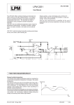
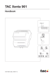
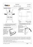
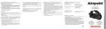
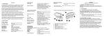
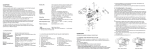
TAC 200 OTP
0FL-3563-000
Heating controller with outdoor reset
User’s Manual
Mounting
Base plate
TAC 200OTP
Cover
Controller TAC 200 OTP
TAC 200 OTP is encased in a plastic enclosure with a
transparent cover. The controller can be mounted in three
ways, either directly on the wall, on a DIN rail or in a panel.
There are cable inlet holes on three sides.
The controller is attached to the base and should be
removed as in figure 1. Mount the base plate in an easily
accessible position where the display is clearly legible.
Connect the wires according to the wiring diagram. Screw
the controller back onto the base plate. There are holes in
the base plate for mounting the controller directly onto the
wall if preferred.
To mount the controller on a DIN rail, see figure 2, place the
controller on the upper edge of the rail and press it inwards
to snap it into place. To remove it again, place a screw driver
in the red piece of plastic on the lower part of the controller,
pull downwards and then pull the controller upwards from the
rail.
Figure 1
To mount the controller in a panel the space needs to be
138×92 mm. Place the controller in the panel and turn the
small plastic hooks in the controller’s screw holes to secure
it.
Outdoor sensor EGU
Mount the sensor on an external wall, facing north or northwest. The sensor should be placed about 3 m above ground
level and the cable inlet should face downwards.
DIN rail
Supply sensor EGWS/EGA
The immersion sensor EGWS is mounted in the riser pipe,
some 0,5–1 m downstream of the mixing valve. If an EGA
strap-on sensor is used, it should be mounted on an uninsulated part of the pipe. Clean the pipe thoroughly so that
the copper contact plate of the sensor makes good contact
with the pipe.
Figure 2
Room sensor EGRL
To achieve the best performance, the following should be
taken into consideration when mounting the room sensor:
•
The sensor should be installed in a room which is typical
of the building.
•
The sensor should be placed on an inner wall of light
building material. The wall must not beheated by, for
example, uninsulated heating pipes behind it.
•
The room should be of sufficient size for the temperature
not to be adversely affected by people or machinery.
•
The radiators in the room should not have thermostat
valves. If they have they should be turned to the largest
value possible.
•
The room sensor should be placed so that the air can
flow freely around it.
•
The room sensor should be placed within 10 m from the
nearest radiator, but not right above it.
Wiring
Connect the cables to the controller according to the wiring
diagram, see figure 3 on the next page. The wires from the
controller are connected between inputs 1 and 2 on the room
sensor.
Length of cables
To terminals B1–B3, and X1–X3: Max. 200 m, area 0,5 mm2.
To other terminals: Max. 100 m, area 1,5 mm2.
Actuator (M44, M5, M15, M42)
Mounting instructions are supplied with the actuator/
mounting kit.
0FL-3563-000, 2000-01
1 (4)
3. Switch on power.
4. Set current time and date, see the next page.
230 V/L
1 L
M 10
230 V/N
2 N
B1 11
3 PE
B2 12
Outdoor sensor
4 KC1
B3 13
Room sensor
5 K1
M 14
6 K2
X1 15
R
M15/
M44 B
Supply temp. sensor
5. Put the brief instruction back in its place.
TAC 200 OTP will now control, using the factory settings. To
set values other than those set at the factory, refer to the
TAC 200 OTP Handbook, part number 0-004-1400.
Forced day op.
(230 V)
W
7 KC2
X2 16
Pump
8 K3
X3 17
Boiler
9 K4
M 18
230 V/L
1 L
230 V/N
2 N
Forced night op.
Brief instruction
Display
3 PE
/
4 KC1
Stage 1
Stage 2
P
5 K1
–
+
P
6 K2
TAC 200
7 KC2
Pump
8 K3
Boiler
9 K4
DIP switches
Buttons
Figure 4
Terminal board connections
1
2
3
4
5
6
7
8
9
10
11
12
13
14
15
16
17
18
230 V/L
230 V/N
PE
KC1
K1
K2
KC2
K3
K4
Mains, phase (live)
Mains, neutral
Protective earth
Power supply, relays K1 and K2
Relay K1: increase/stage 1
Relay K2: decrease/stage 2
Power supply, relays K3 and K4
Relay K3: circulating pump
Relay K4: boiler
M
B1
B2
B3
M
X1
X2
X3
M
Measurement neutral
Supply sensor, EGWS/EGA
Outdoor sensor, EGU
Room sensor, EGRL
Measurement neutral
Input, forced day operation
Input, forced night operation
Not in use
Measurement neutral
1 2
1. Check that sensors and actuators are correctly wired.
2. Set the switches on the DIP switches on the circuit board,
located under the brief instruction, as required, see
figure 4 and 5.
5
6
7
8
off (0)
Factory setting, 1–8: 1000 000
P:nn in the display indicates the current function used, see
figure 6. P:00, for example, means time of day and operating
mode.
P
+
P
Use these buttons to move up and down the list.
–
Use these buttons to increase or decrease the
value shown on the display. Keep either of them
depressed to increase the stepping speed.
Use this button to change between day and
night in segments of 30 minutes.
To save alterations, press
P
or
again. Failure to carry
P
out this step will result in the changes not being saved and
the controller reverting to the old value in approximately two
minutes.
7
8
9
10
11
12
13
14 15
16
17
18
6
Switch
Position off (0)
Position on (I)
1
on/off control
mixing valve
2
radiator system
floor heating
3
no room sensor installed
room sensor
4–7
(no function)
5
(hardware reset when switched 0–1–0)
MO
TU
3
P:00
2
1
WE
TH
FR
SA
SU
19
4
0
8
Figure 5
Operator’s panel
/
After the controller has been mounted and the electrical
wiring is completed, the following checks should be carried
out and the settings entered before operation of the
installation.
4
on (1)
Figure 3
Commissioning
3
K4
12:34
AM
°C
Ι ΙΙ
20
21
22
23
24
Figure 6
Switches 4–8 should be in the off position.
2 (4)
0FL-3563-000, 2000-01
Setting time and date
Setting time program
1. Press
The digital clock has a time program, which is used for
switching between day and night temperature. All times can
be set individually for every day of the week, with a resolution
of 30 minutes. The segments—each is 30 minutes long—on
the 0–24 scale show when day and night temperature are
used, starting with Monday (MO displayed). A black segment
denotes day temperature setpoint and a white one night.
P
or
P , until P:13 (Set time) is displayed.
2. Press either + or
– until the controller shows current
time, e.g. 09:45. Keeping the button depressed increases
the stepping speed.
3. Press
P , so that P:14 (Day.Month) is displayed.
1. Press
4. Press + or
– until the controller shows current date
e.g. 29.11.
5. Press
P
– until the controller shows current year,
e.g. 1994.
P
so that P:00 (Time) is displayed. The time
P
or
P
is not pressed as the last step, any changes
will not be stored (applies to all entries). In this case the
display will automatically revert to P:00 in about two minutes.
Note! TAC 200 OTP automatically switches to and from
daylight saving time, even in leap years. The dates for
change over can be set manually if desired.
Current temperatures
1. Press
P
or
P , to display P:01, P:02, P:03 or P:04.
P:01
room temperature (if a room sensor is installed)
P:02
outdoor temperature
P:03
supply water temperature
P:04
supply water temperature setpoint
P
4. If you press + , and you are at the last segment, the
segment and press
– , the display changes to the
previous day.
5. Mark all the segments of all day-and-night periods as
desired.
6. Use the same procedure to mark the segments for each
day of the week.
7. Store the changes by pressing
P
or
P
at least once.
If the same pattern for day/night setpoint is required for
several days, either repeat the above or, for speed, use P:09
(Time program, 1–7 days). The days of the week and the
0–24 segments can then be changed in the same procedure.
P
or
P
until P:09 (Time program, 1–7 days) is
displayed.
3. Press
/
– until the first day to be removed flashes.
. The marked day disappears.
4. Remove all the days for which the change should not
apply in the same way. Make sure that the days to which
the changes apply, are visible on the display.
5. The flashing weekday indication will automatically skip to
the segments of 30 minutes when passing either Sunday
or Monday (in reverse direction).
Setting temperature setpoint
or
– until you reach the segment you want to
3. Press / . The colour of the segment changes and the
flashing skips to the next segment.
2. Press + or
2. The current value is continually updated, but after about
two minutes the display reverts to P:00 (Time/Operating
mode).
P
until P:08 (Time program, day-by-day)
change. The segment flashes.
1. Press
Function displays current
1. Press
P
display changes to the following day. If you are in the first
value is now stored.
If
or
2. Press + or
so that P:15 (Year) is displayed.
6. Press + or
7. Press
P
is displayed.
to display P:05, P:06 or P:07.
6. When day setpoint is required, mark the segments in the
same way as above.
or
to save the changes.
Function displays
7. Press
P:05
8. To set other times for other days, return to P:09 and
repeat steps 2–7 for these days.
room temperature setpoint (°C) (with room
sensor)
P:06
night setback (°C) (with room sensor)
P:07
parallel shift of reset curve (°C) (without room
sensor).
P
P
Note! Take care as this operation changes several days at
the same time.
2. Press + or – until the display shows desired value.
Keeping the button depressed increases the stepping
speed.
3. Store changes by pressing
0FL-3563-000, 2000-01
P
or
P
at least once.
3 (4)
To change operating mode
Power failure
The temperature of the building can be lowered for a longer
period of time, e.g. if it is empty during a holiday, or if the day
temperature is required for a couple of hours extra one night,
without changing the TAC 200 OTP program. The controller
can also provide day or night temperature all the time or be
turned off without losing the settings.
The controller maintains the settings for at least twelve hours
during a power failure. The clock keeps running and when
the power returns, the controller continues to control the
system as if nothing had happened. Should the power failure
last longer than twelve hours, the time, date and year will
require re-setting.
It is possible to toggle between the following operating
modes on the operator’s panel:
Restart
Forced off
If the controller has stopped working, it may need to be
restarted. To do this switch DIP switch 8, behind the brief
instruction on the front of the controller, to on and then back
to off. All the settings remain in the controller.
Forced night operation
Automatic operation (control by the time program)
To restart the controller and regain the factory settings:
Forced day operation
1
Press
P
and
During forced off, the controller is turned off without loosing
the settings.
2
Press
P
or
During forced night operation the controller provides night
temperature all the time. In the same way, the controller
provides day temperature all the time during forced day
operation.
3
Press + .
During automatic operation, the controller provides day and
night temperature according to the programmed settings.
P
P
to reach P:16.
until P:54 is shown on the display.
Accessories
TAC 200 OTP Handbook, part number 0-004-1400.
To change the operating mode:
1. Press
P
or
P
until P:00 (Operating mode) is
displayed (if it is not already shown).
2. Press + or – until the desired symbol is activated.
If forced day or night operation has been activated from
outside the controller (Extended day/night operation, see the
handbook), the corresponding symbol flashes.
Externally forced operation (X1, X2) has a higher priority
than any locally forced operation.
To access other functions
Normally it is sufficient to use P:00–P:15 and for this reason
the display scrolls through P:15–P:00 or vice versa.
To access functions P:16 and higher:
1. Simultaneously press
2. Press
P
or
P
P
and
P
to get to P:16.
to step up or down within the new
interval. To return to P:00–P:15, either press P and
P
simultaneously, or wait for approximately two minutes for the
controller to return to P:00 automatically.
Depending on the specific configuration, certain non-relevant
functions may be missing.
TAC AB, Jägershillgatan 18, SE-213 75 MALMÖ, SWEDEN, +46 40 38 68 50 (vx)
4 (4)
English
0FL-3563-000, 2000-01