1
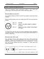
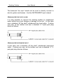
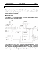
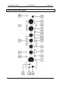
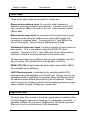
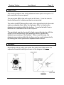
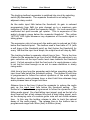
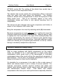
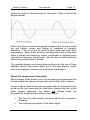
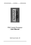
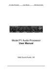
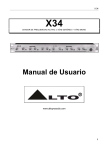
Tracking Toolbox User Manual Safe Sound Audio Tracking Toolbox User Manual Safe Sound Audio, UK Tracking Toolbox User Manual Page 2 Tracking Toolbox Features Input Stage High bandwidth microphone amplifier with classic balanced discrete transistor front end. Front panel selection to balanced line level or high impedance instrument inputs. Switchable 80Hz, 18dB/octave hi-pass filter and balanced insert point are included. Compressor Advanced audio compressor with peakride which uses multiple sidechains in tandem allowing for very musical dynamic control of source material. Peakride compression is very easy to dial in when tracking and evens out levels in a very musical way without robbing the sound of life, so bringing the performance a new energy. Auto gain makeup allows you to increase gain reduction ‘on the fly’ without having to constantly readjust the output level. Expander New expander design with auto hold and release times. Ideal for voice over artists. Variable attack limiter design Switchable fast limiter offers ultimate protection during tracking or push it hard as a great dynamic effect especially on bass and drums. Fast clipping protection when tracking but also very useful as a creative tool in its own right when pushed into heavy levels of limiting. Output stage and monitoring Fully balanced output stage will drive +27dBu into 600 ohms with a useful ±15dB of output gain control available. Balanced stereo monitor inputs with separate source level control providing zero latency headphone monitoring of the source/replay mix. 100% linear internal mains power supply Tracking Toolbox User Manual Contents Tracking Toolbox Features Safety Information; READ THIS FIRST Installation Audio connector wiring information Quick Start guide Detailed Operation Guide Front Panel layout Rear Panel layout Input Stage High Pass Filter Insert point Expander Peakride Compressor Peakride Compressor Design Theory Limiter Output Gain and Level Metering Monitoring chain Ground lift switch Technical Specification Warranty How to contact us Page 3 Page 2 4 6 7 9 10 10 11 12 12 13 13 15 16 18 19 19 20 20 23 24 Tracking Toolbox User Manual Page 4 Important Safety Information : Read this first! There are dangerous voltages present within the unit. Do not open the unit and refer all servicing to qualified service personnel. The lightning flash with arrowhead symbol, within an equilateral triangle, is intended to alert the user to dangerous voltages within the unit. The exclamation point within an equilateral triangle is intended to alert the user to important operating and safety instructions in this user handbook. Tracking Toolbox User Manual Page 5 This unit must be earthed. This unit should only be connected to a mains supply of the type marked on the rear of the appliance. Take special note of the required mains voltage. The IEC mains connecting lead originally supplied with this unit has been fitted with a 3A mains fuse. Always replace with a fuse of the same rating. (UK plugs only) This unit is fitted with an externally accessible fuse. Always replace with a fuse of the same type and rating. The fuse type and rating are shown on the rear of the unit just above the fuse receptacle. Always disconnect the unit from the mains supply before replacing this fuse. Always use a slow-blow anti-surge type fuse. The operating mains voltage may be selected inside the unit. Ensure that the selection instructions are closely followed and if in doubt always have this done by a qualified technician. Mounting points are provided on the case for the optional 19” rack mount ears. You should only use the mounting screws supplied with the rack mounting kit. If 19” rack mounting this unit it is advisable to leave a ventilated space above the unit. Tracking Toolbox User Manual Page 6 Installation The tracking toolbox is supplied in a foam lined shipping carton and should arrive with you in perfect condition but it is always worth checking the unit for any signs of physical damage before use. Should you have a concern that the unit appears damaged then contact your dealer. The unit will have been factory set to operate from the mains voltage shown on the rear label. It is possible to change the mains operating voltage, by a switch inside the unit. The selection is between 115VAC and 230VAC. Access to the switch requires the removal of the unit’s top cover (4 screws). If you do require to change the operating voltage then ensure you label the unit accordingly. New voltage labels are available from Safe Sound Audio. If in doubt, always have this done by a qualified technician. The optional rack ears may be screwed to the sides of the unit with the screws provided. Ensure these are adequately tightened as the unit is quite heavy. Do not use screws longer than those provided. The correct screw type is M3 x 6mm countersunk posi-head type. Connect the unit to a suitable source of mains power, connect audio and check through the functionality of the tracking toolbox according to the guidance in this manual. If for any reason you require to replace the rear panel mains fuse then take care when removing the fuse holder. First always remove the mains cord. Then use a flat blade screwdriver. Apply to the slot in the fuse holder, then apply pressure to push the fuse holder in against the retaining spring, then turn anti clockwise until the fuse holder is released. Replace the fuse with the same slow-blow antisurge type and then reinsert the fuse holder into the unit. Should the unit’s fuse continue to blow then remove the mains cord and contact your dealer for service. Tracking Toolbox User Manual Page 7 Audio Connector wiring information Note: All connector wiring information refers to the cable end connecting to the tracking toolbox unless otherwise stated. BALANCED MICROPHONE INPUT Any standard balanced XLR-3 to XLR-3 microphone cable should be suitable. At the tracking toolbox end, use a cable type XLR-3 pin plug wired as follows; Pin 1 = Pin 2 = Pin 3 = screen signal +ve (also called ‘in phase’ or ‘hot’) signal -ve (also called ‘anti-phase’ or ‘cold’) You should not use this input to connect unbalanced high impedance microphones which in any case are normally supplied terminated in a 2-pole ¼” jack plug. BALANCED LINE LEVEL AUDIO Any standard ‘off the shelf’ balanced line level cable should be suitable. These will be typically either jack to jack or jack to XLR depending on the type of equipment you are connecting to. If wiring your own, at the toolbox end use a standard ¼” 3-pole jack plug wired as follows; Tracking Toolbox User Manual Page 8 The balanced ‘line input’ should not be used to directly connect to electric guitars and basses. Use the INSTRUMENT input instead. UNBALANCED LINE LEVEL AUDIO It is also possible to connect the tracking toolbox to unbalanced audio without any level change or damage to the unit. In this case use a standard ‘off the shelf’ unbalanced line level cable. If wiring your own, at the toolbox end use a standard ¼” 2-pole jack plug wired as follows; UNBALANCED INSTRUMENT INPUT In this case use a standard ‘off the shelf’ unbalanced instrument cable. If wiring your own, at the toolbox end use a standard ¼” 2pole jack plug wired as follows; Tracking Toolbox User Manual Page 9 Quick Start Guide After reading the important safety information, you may wish to ‘plug and go’. If, at any time, you are in doubt as to the correct operation of the unit, all operational points are covered in detail later in this manual, but as a quick start; BASIC FUNCTIONS The tracking is a mono audio path processor with separate stereo monitoring facility, as shown below; The three audio inputs have separate connectors but only one of these inputs is connected to the main processing chain at any one time. Selection between mic and line inputs is controlled by a switch on the front panel. Plugging in a jack plug to the front panel instrument jack automatically selects that as the source. Tracking Toolbox Detailed operational guide User Manual Page 10 Tracking Toolbox User Manual Page 11 Tracking Toolbox User Manual Page 12 Input Stage Three audio input types are provided for, these are: Balanced microphone input, for use with either dynamic or phantom powered condenser microphones. Connect via the XLR input connector (24) on the rear of the unit. Select switch number (14) to ‘mic’. Balanced line level input, for use with any line level source, most commonly when using the toolbox as an insert effect within the recording or mixdown chain. Connect via the ¼” jack (28) on the rear of the module. Switch number (14) selected to ‘line’. Unbalanced instrument input, for direct injection of most electric or bass guitars. This is sometimes called the DI-INPUT (direct injection). Connect via the ¼” jack (13) on the front of the module. Insertion of the jack connects the input to the audio chain. All three input types have different gain ranges available to suit the type of source, all controlled from a single gain control (1). PEAK LED (16) will light when the audio path comes within 3dB of the available input headroom. +48V Phantom power is switched on by selecting switch (15) downwards and the adjacent red LED will light. Always connect the microphone before switching on phantom power and always switch off phantom power before disconnecting the microphone. Always best to mute your monitoring chain first as switching phantom power cause audible ‘thumps’ through your audio chain. High Pass Filter The high pass filter is sited in the audio signal path immediately after the input stage but before the insert point, compressor and limiter. It operates at 80Hz with a slope of 18dB/octave. Bring the high pass filter into circuit by selecting switch (2) downwards. Tracking Toolbox User Manual Page 13 Insert Point The tracking toolbox has a fully balanced insert point via a pair of ¼” jack sockets on the rear panel. The send jack (22) is fed with audio at all times. It can be used to feed a balanced or unbalanced device as required. The return jack (27) brings the insert return signal back into the main audio processing chain, after the high pass filter, but before the dynamics processing within the toolbox. It can be fed with from a balanced or unbalanced device as required. The send jack can also be used to feed a recording device with the output of the mic/line/instr input amplifier before it enters the dynamics processing of the toolbox. When used this way, the dynamics processing within the toolbox can be used independently by feeding the return jack with a separate audio source. Expander Expanders reduce audio gain when the audio level falls below the expander threshold setting as shown in the diagram below; Tracking Toolbox User Manual Page 14 The tracking toolbox’s expander is switched into circuit by selecting switch (3) downwards. The expander threshold is set using the adjacent rotary control. As the audio input falls below the threshold, its gain is reduced progressively from 0dB (no gain change) up to a maximum gain reduction of 20dB (called the expander depth). So loud sounds are unaffected but quiet sounds get quieter. This is expansion of the audio’s dynamic range below the expander threshold. The yellow ‘ACTIVE’ LED lights whenever any expansion of the audio signal is taking place. The expansion ratio is how much the audio gain is reduced as it falls below the threshold point. The toolbox uses a fixed ratio of 1:2 (with a soft knee at the threshold point) so that (below the threshold) for every 1dB that the input level drops, the output level will drop by 2dB. The tracking toolbox’s expander attack time is 3ms. This is the time it takes for the expander to go from the full 20dB gain reduction to no gain reduction as the input audio level rises towards the threshold point. It’s fast enough so that the front end of a vocal phrase or note is not lost but slow enough so as not to cause distortion in slowly rising audio. Hold time is how long the expander waits before operating when the input level falls below the threshold setting. The toolbox’s hold time is programmed to follow the natural dynamics of the audio signal. Short duration audio phrases have a short hold time whereas long audio phrases have a longer hold time. Release time is the time it takes the expander to reduce the audio gain as the input level falls below the threshold setting. The toolbox’s’s release time is programmed to follow the dynamics of the falling audio signal. So a fast falling input signal, such as the tail of a drum beat will set a fast release time and a slow falling signal, such as the decaying note of a sustain guitar note will set a slow release time. In this way the toolbox release is able to track the natural decay of the audio signal. The release time in the toolbox has a programmed range from 90ms (fast) to 900ms (slow). Tracking Toolbox User Manual Page 15 Expanders are often compared to noise gates, but in general use expanders are more natural sounding because their control of audio gain is directly related to the audio signal characteristic which is not the case in a noise gate. Peakride Compressor Compressors progressively reduce the gain of an audio signal as its input level rises above the compressor threshold as shown in the diagram below. The compressor threshold is the level point in dB above which the audio gain will be reduced. On the tracking toolbox this can be varied from 0dB to -40dB using the THRESHOLD control (7). The ratio control (4) varies the degree of gain reduction which is applied, from 1:1 (no effect) to 30:1 which will make the compressor act like a limiter. The attack time is how quickly the compressor will react to audio which rises above the threshold point. In the tracking toolbox the attack time can be varied from 60ms (slow) to 1ms (fast) using the Tracking Toolbox User Manual Page 16 ATTACK control (5). The setting of the attack time usually has a large impact on the compression effect. The release time is how quickly the compression effect is removed when the audio falls back below the threshold. The tracking toolbox’s release time is programmed to follow the dynamics of the falling audio level. This is an important aspect of the unit’s compressor design and offers a very natural sounding form of compression. The amount of gain reduction (due to the compressor and limiter) is shown in the 8 segment LED meter (18). Bring the compressor into circuit by selecting switch (6) downwards. Because compression is a gain reduction tool, it will tend to lower the maximum audio level through the audio chain. Make-up gain is used to replace this ‘lost’ level and in the case of the tracking toolbox this is done automatically; the amount of make-up gain applied being related to the threshold and ratio setting. Auto gain make-up is really useful as it allows you to increase gain reduction ‘on the fly’ without having to constantly readjust the output level. Peakride Compressor design theory With so many analogue and digital compressors on the market today, we decided to try a new approach to single audio band compression which gives most of the advantages of multi-band compressors (plus a few more!) without the operational complexity of band splitting. The full story of peakride compression is told in our design white paper but here are the highlights; It’s desirable for a compressor to be able to offer a wide range of attack and release times to suit a variety of source material. For example, percussion typically requires medium fast attack and release times whereas some vocals require quite fast attack times and medium/slow release times. Fast attack, fast release compressors often have poor audio performance especially distortion Tracking Toolbox User Manual Page 17 caused by ripple of the side-chain by the audio. Have a look at the diagram below; Notice that the pure tone audio signal is beginning to lose its smooth top and bottom curves and begins to resemble a triangular waveform. This is not just an issue for bass guitar and bass drum compression. Many audio sources including piano and vocals have either a primary low frequency ‘carrier’ component or vibrato/tremolo induced low frequency components. All can cause audible distortion when being compressed or limited. The peakride design overcomes these problems by the use of three separate control side-chains which act in the time domain (rather than in the frequency domain of a multi-band compressor). Above the compressor’s threshold; Short duration audio bursts (such as percussion) get processed with the fast attack fast release compression which they tend to require. Longer duration audio bursts get processed with an initial attack time as set on the front panel and an initial short release time but; as the audio sample continues, the attack and release times are progressively lengthened according to two factors; The time the audio sample has been above the compressor threshold The continuing dynamics of the audio signal Tracking Toolbox User Manual Page 18 A second problem with traditional fast attack compressor designs is caused by a misunderstanding between the desirability for fast attack, especially to provide adequate control of certain vocal styles, and the usual consequence that the whole vocal phrase then suffers from over compression. It is often difficult to achieve the attack speed without the undesirable over compression. The peakride compressor achieves this by altering the ratio of the compressor dynamically. So you can set an average compression ratio on the front panel control but the actual delivered ratio will alter to suit the dynamics of the audio as it rises above the threshold level. These principles are at the heart of the peakride design and are achieved by mixing the three compressor side-chains at different levels and with different compression ratios. In effect, the compressor side-chain is able to ride the peaks of the audio, reacting quickly but smoothly to fast attack peaks, and then able to track the dynamics of the continuing audio till it falls below the threshold point. Limiter The tracking toolbox includes a switchable audio limiter which can be used to prevent digital clipping in your recording chain. The limiter is sited in the audio signal path immediately before the output level control and operates at fixed threshold of +6dBu (nominal). The limiter features dynamic adjustment of attack time, so the faster the audio front edge, the faster the limiter reacts. So fast clipping protection when tracking but also very useful as a creative tool in its own right when pushed into heavy levels of limiting. We’ve added a programme tracking release circuit which provides for very smooth recovery from limiting, adapting to the natural dynamics of the audio source. Bring the limiter into circuit by selecting switch (8) downwards. Tracking Toolbox User Manual Page 19 Output Gain and Level Metering The output gain control (10) is sited in the signal path immediately after the limiter and just before the final balanced output stage which in turn feeds the line output jack socket on the rear of the unit (23). The most common use of the output gain control is to match the peak output level of the tracking toolbox to the peak input level of your recording device. Once you have done this level matching it’s usually not necessary to alter the output gain control during recording. The level meter (19) is intentionally placed BEFORE the output gain control. We suggest you use the level meter in conjunction with the INPUT gain control during recording set-up so that the maximum audio level during tracking is lighting one or both of the yellow level LED’s but not intentionally lighting the red level LED. When switched into circuit the unit’s limiter will keep the maximum output level below 0dB (nominally +6dBu). Operating at higher nominal recording levels (e.g. +18dBu) is also possible by switching the limiter off and using only the recording meters in your recording device to monitor the maximum desired recording level, but on the whole it is better to operate below the unit’s 0dB point (red LED) then use the output gain control for additional post limiter gain. This provides the optimum balance between noise and distortion performance. The Monitoring Chain A stereo input is provided to be fed from the replay chain of your recording device. Connected on the rear panel via two 3 pole ¼” jacks for balanced stereo connection (21) and (26). The monitoring chain feeds the front panel ¼” stereo headphone socket (12) best connected to headphones with an impedance of 600 ohms or above. The headphone level is adjusted by a rotary knob (11). Tracking Toolbox User Manual Page 20 For track laying and overdubbing, it is also possible to mix in a feed of the unit’s main processor path which has it’s own ‘source monitor’ level control (9). This monitor control does not affect the unit’s main audio path level. Ground lift switch Occasionally you may experience problems with hum loops, especially where the ground system in the studio or venue is less than ideal. The Tracking Toolbox has a ground lift switch (25) which, when switched downwards, isolates the sleeve of the audio jack from ground (at the Toolbox end) so removing a possible ground loop problem. It is best to operate the ground lift switch only if you have a hum problem. This does not compromise electrical safety. NEVER remove the mains earth in attempting to deal with a hum problem. This is dangerous and compromises your safety. Technical Specification TRACKING TOOLBOX AUDIO PROCESSOR Physical Size : 220mm wide by 44mm high (1U) by 225mm deep (excluding cable connectors) Weight : 2.2kg (4lbs 10oz) Power requirements : AC power to the voltage indicated on the rear panel 10%, 50/60 Hz. Internally switchable between 115 and 230VAC. Mains Plug fuse : Rear panel fuse : Power consumption : 3A (UK plugs only) 20mm fuse, 250mA 250V slow-blow 15W Tracking Toolbox User Manual Page 21 Main processor audio path Frequency response : -0.5dB points at 5Hz and 60kHz Distortion : < 0.01% at 1kHz (typically 0.007%) main signal path working at 0dBu Maximum input levels (input gain set to minimum) Microphone : Line input : Instrument : +20dBu +27dBu +18dBu Input impedances Microphone : Line input : Instrument : 2k4 ohms > 10k ohms 1M ohms Equivalent input noise figure Microphone : 128dB (max gain with 150 ohms source) High Pass Filter Switchable 80Hz hi-pass filter with 18dB/octave slope Balanced Line Output Output Gain : ±15dB (post limiter) Maximum Output Level (post limiter) : +27dBu Output impedance: 50 ohms Output Noise : -91dBu RMS unweighted, measured 22Hz to 22kHz -93dBu RMS A-weighted, measured 22Hz to 22kHz Tracking Toolbox User Manual Page 22 Input Gain Ranges Microphone input : Line input : Instrument input : -5dB to +70dB -10dB to +20dB +4dB to +35dB Peakride Compressor Threshold range : 0dB to -40dB Attack time range : 60ms to 1ms Release time : variable from 90ms to 500ms (tracks the natural audio decay) Ratio : 1:1 to 30:1 Make-up gain : automatically set in proportion to the threshold and ratio settings Gain reduction meter : calibrated in dB’s Dynamic Attack Limiter Threshold : fixed internally to +6dBu (nominal) Attack time : audio related with a fastest response of 0.5ms Release time : audio related from 50ms to 500ms Metering Level metering : 8 element LED display measuring -21dB to 0dB (0dB equates to Limiter Threshold) Gain Reduction : 8 element LED display Tracking Toolbox User Manual Page 23 Warranty Safe Sound Audio provides a 12 month warranty from the purchase date according to the following conditions; This warranty is not transferable and applies only to the original purchaser of the unit. If the unit should become faulty, then contact Safe Sound Audio or your local distributor for a Returns Authorisation Number. No items will be accepted for warranty repair without this authorisation number. You must be able to produce proof of the purchase date. If the returned unit should prove faulty then, at Safe Sound Audio’s choice, we will either repair or replace the unit. The customer is responsible for the cost of sending the unit back to Safe Sound Audio or our authorised distributor including insurance of the unit during shipping. Safe Sound Audio or our authorised distributor will be responsible for the cost of shipping the repaired or replaced unit back to the customer including insurance of the unit during shipping. The warranty will be void if the unit has; Suffered physical damage. Been repaired or modified by anyone other than Safe Sound Audio or its authorised representative. Has been connected to an incorrect source of power. Has been damaged due to liquid spillage. Safe Sound Audio shall not be liable for any special or consequential damages resulting from the use of this product. Tracking Toolbox User Manual Page 24 How to contact us By post : Safe Sound Audio 47 Broadgate Lane Horsforth Leeds West Yorkshire LS18 4AG UK Callers strictly by appointment By telephone : +44 (0)7866 574 522 By e-mail : [email protected] On the web : www.safesoundaudio.com Safe Sound Audio reserves the right to make changes and improvements to the design of this product without notice. © Safe Sound Audio 2011