1
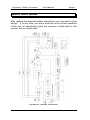
Dynamics Toolbox Processor
User Manual
Safe Sound Audio
Dynamics Toolbox
Audio Processor
User Manual
Safe Sound Audio, UK
Dynamics Toolbox Processor
User Manual
Page 2
Dynamics Toolbox Features
Compressor
Two great stereo linkable compressors in one package PLUS a
choice of ‘peakride’ or ‘dynamic tracking’ compression, so a
fantastic range of compression for tracking and mixing.
Includes the fabled ‘New York’ parallel compression - very rare in a
stereo linkable compressor.
Allows an infinite blend of
compressed and uncompressed material.
Flexible sidechain
Built in sidechain filters to add lo end punch or hi end sparkle plus
full insert access to the sidechain path so you can add an
additional external processor.
Fully stereo linkable
Control all compression and limiting functions in stereo link mode
from one set of controls (channel 1 is the master when linked).
Limiter
New user adjustable threshold limiter for ultimate protection and
great as a dynamic effect when used with the ‘New York’ blender.
Output stage
Superhigh +27dBu output level feeding both electronic balanced
outputs and a plug-in range of output transformers : so now you
can choose your favourite Lundahl, Sowter, Jenson or Cinemag
transformers.
Calibrated output gains pots with centre detent line-up position.
100% linear internal mains power supply (throw away those wall
warts for good!)
Dynamics Toolbox Processor
User Manual
Contents
Dynamics Toolbox Features
Safety Information; READ THIS FIRST
Quick Start Guide
Fitting the optional transformer cards
Changing the mains operating voltage
Audio Connector wiring information
Detailed Operational Guide
Power on
Typical audio connections
Operating levels
Using the unit in stereo link mode
The compressor
Accessing the compressor’s side-chain
‘New York’ parallel blend compression
The limiter
Peakride compressor design theory
Dynamic Tracking compressor design theory
Limiter design theory
Answers to some common questions
Technical Specification
Fault finding
Customer Care
Warranty conditions
How to contact us
Page 3
Page
2
4
6
9
12
15
17
17
18
19
20
20
25
26
28
29
31
33
37
38
41
43
43
45
Dynamics Toolbox Processor
User Manual
Page 4
Important Safety Information : Read this first!
There are dangerous voltages present within the unit. Do not
open the unit when powered and refer all servicing to qualified
service personnel.
The lightning flash with arrowhead symbol,
within an equilateral triangle, is intended to
alert the user to dangerous voltages within
the unit.
The exclamation point within an equilateral
triangle is intended to alert the user to
important operating and safety instructions
in this user handbook.
Dynamics Toolbox Processor
User Manual
Page 5
This unit must be earthed.
This unit should only be connected to a
mains supply of the type marked on the
rear of the appliance. Take special note of
the required mains voltage.
The IEC mains connecting lead originally
supplied with this unit has been fitted with a
3A mains fuse. Always replace with a fuse
of the same rating. (UK plugs only)
This unit is fitted with an externally
accessible fuse. Always replace with a
fuse of the same type and rating. The fuse
type and rating are shown on the rear of
the unit just below the fuse receptacle.
Always disconnect the unit from the mains
supply before replacing this fuse.
Optional transformer cards may be fitted to
this unit. Ensure that fitting instructions are
closely followed and if in doubt always have
the fitting done by a qualified technician.
The operating mains voltage may be
selected inside the unit. Ensure that the
selection instructions are closely followed
and if in doubt always have this done by a
qualified technician.
Dynamics Toolbox Processor
User Manual
Page 6
Quick Start Guide
After reading the important safety information, you may wish to ‘plug
and go’. If, at any time, you are in doubt as to the correct operation
of the unit, all operational points are covered in detail later in this
manual, but as a quick start;
Dynamics Toolbox Schematic
Dynamics Toolbox Processor
User Manual
Page 7
BASIC FUNCTIONS
The Dynamics Toolbox is a two channel audio compressor/limiter
which can be linked for stereo operation or each channel can be run
completely independently with separate compression modes, parallel
compression blends, sidechain EQ and limiting for maximum
versatility.
POWERING
AC Mains powered via a standard IEC mains connector, internally
switchable to either 115V or 230/240V operation. Make sure you
connect to the correct mains voltage as shown on the rear panel
label.
AUDIO CONNECTIONS
All audio inputs and outputs are balanced but may be connected to
unbalanced equipment if required. The ¼” jack connector wiring
follows normal audio convention. Details are given later in this
manual.
COMPRESSOR
A sophisticated compressor with a choice of two compressor types;
Peakride multi side-chain compressor with variable threshold, attack
and ratio. ‘Follow-audio’ auto release time.
Dynamic Tracking compressor with variable threshold, attack,
release (with auto release option) and ratio.
Both compressor types have 0 to +20db of make up gain available.
COMPRESSOR SIDE CHAIN
Full access sidechain with sweepable hi and lo pass filters, balanced
insert point and ‘listen to sidechain’ function.
Dynamics Toolbox Processor
User Manual
Page 8
LIMITER
Variable threshold fast limiter. Uses a separate side-chain to the
compressor and so is unaffected by changes to the sidechain filters
ensuring protection from overloads.
NEW YORK BLEND FUNCTION
‘New York Compression’ became a trade mark sound of many New
York based mixing engineers and uses a form of parallel
compression which mixes in a small amount of very heavily
compressed stereo submix (usually drums or rhythm guitars) back
into the main uncompressed mix. The beauty of this technique is
that since you have full control of the blend between compressed
and uncompressed submix strands, you retain the timbre and
dynamics of the original submix whilst adding gritty texture via the
heavily compressed element.
STEREO LINK FUNCTION
Links channel 1 and channel 2 for stereo operation. All functions are
controlled from channel 1 with the exception of the metering, output
gain and sidechain ‘listen’.
BYPASS FUNCTION
Relay switched bypass function which also provides auto-bypass
when the mains power to the unit is switched off.
VU METERING
Switchable pre and post the output gain control and to gain
reduction. 0VU line up level may be switched to either +6dBu or
+18dBu.
Dynamics Toolbox Processor
User Manual
Page 9
Fitting the optional output transformer cards
There are dangerous voltages present
within the unit. Do not open the unit when
powered and ensure that the transformer
cards are fitted by a technically competent
person. If in any doubt contact Safe Sound
Audio for further advice.
Please follow these instructions carefully.
With the AC power lead disconnected, place the Dynamics
Toolbox on a flat well lit workbench.
Remove the six posi-head screws from the top cover panel and
carefully lift the top panel away from the unit. NOTE that the top
panel has a safety earth cable connection. Rotate the top panel and
lay beside the unit.
Dynamics Toolbox Processor
User Manual
Page 10
Check that the connector pins of the transformer cards are straight
and undamaged.
Insert each transformer card into the
corresponding sockets in the unit’s main motherboard taking great
care to correctly align the six pins on each transformer connector
with the corresponding pins in the motherboard sockets.
Correct positions of connector pins just before pushing the
transformer card down into its final position
Dynamics Toolbox Processor
User Manual
Page 11
INCORRECT positions of connector pins. NOTE the pin misalignment.
Misalignment of pins can cause electrical damage of the unit.
Ensure that the transformer cards are pushed fully in.
Replace the top cover taking care to ensure that the safety earth
cable is not snagged but is fully inside the unit.
Dynamics Toolbox Processor
User Manual
Page 12
Reinsert and tighten the six top cover fixing screws.
Apply power and check that the unit’s green power LED is lit.
Check for correct functioning of the unit and for audio at the two
transformer balanced output jacks.
If, at any time, you require to ship the unit
back to Safe Sound Audio or one of our
authorised distributors, ALWAYS remove
the audio transformer cards prior to
shipment and pack separately for transit.
Changing the mains operating voltage
The Dynamics Toolbox can be set internally to operate from either
115VAC or 230VC. (Note that selection to 230VAC is also suitable
for operating the unit from a 240VAC supply.
There are dangerous voltages present
within the unit. Do not open the unit when
powered and ensure that mains operating
voltage is set by a technically competent
person. If in any doubt contact Safe Sound
Audio for further advice.
Please follow these instructions carefully.
With the AC power lead disconnected, place the Dynamics
Toolbox on a flat well lit workbench.
Dynamics Toolbox Processor
User Manual
Page 13
Remove the six posi-head screws from the top cover panel and
carefully lift the top panel away from the unit. NOTE that the top
panel has a safety earth cable connection. Rotate the top panel and
lay beside the unit.
Mains voltage set to 230VAC
Mains voltage set to 115VAC
The mains voltage selector switch is located near the IEC power
connector to the rear of the unit. Select the desired operating
Dynamics Toolbox Processor
User Manual
Page 14
voltage by sliding the switch into the correct position as shown in the
pictures above.
Replace the top cover taking care to ensure that the safety earth
cable is not snagged but is fully inside the unit.
Reinsert and tighten the six top cover fixing screws.
If you are changing the mains operating voltage it will be necessary
to also change the external mains fuse. The correct values are as
follows;
230/240VAC operation : fuse value is 310mA (20mm quickblow type)
115VAC operation : fuse value is 500mA (20mm quickblow type)
Once you have completed the voltage selection procedure above it is
essential to relabel the rear panel markings to show the new mains
voltage and fuse value which has been selected. Labels can be
obtained from Safe Sound Audio on request.
Once all of the above procedure has been completed, apply power to
the unit of the correct voltage and check that the unit’s green power
LED is lit and that the unit operates correctly.
If the green power LED does not light then refer to the fault finding
section of the user manual.
Dynamics Toolbox Processor
User Manual
Page 15
Audio Connector wiring information
Note: All connector wiring information refers to the cable end
connecting to the Dynamics Toolbox audio processor unless
otherwise stated.
BALANCED LINE INPUTS (INCLUDING SIDECHAIN INSERT RETURNS)
Any standard ‘off the shelf’ balanced line level cable should be
suitable. These will be typically either jack to jack or jack to XLR
depending on the type of equipment you are connecting to the line
input. If wiring your own, at the Dynamics Toolbox end use a
standard ¼” 3-pole jack plug wired as follows;
It is also possible to feed these inputs from an unbalanced source
which may still occasionally be required when feeding the Dynamics
Toolbox from some semi-pro sound cards. In this case you can use
either balanced or unbalanced audio cables but balanced cables are
recommended.
Balanced line inputs should not be directly
connected to microphones, electric guitars and basses which must
be connected via a suitable pre-amp.
BALANCED LINE OUTPUTS (INCLUDING SIDECHAIN INSERT SENDS)
Any standard ‘off the shelf’ balanced line level cable should be
suitable. These will be typically either jack to jack or jack to XLR
depending on the type of equipment you are connecting to the line
output. If wiring your own, at the Dynamics Toolbox end use a
standard ¼” 3-pole jack plug wired as follows;
Dynamics Toolbox Processor
User Manual
Page 16
It is also possible to feed the unit’s outputs to an unbalanced
destination which may be the case when feeding the Dynamic
Toolbox line outputs to some semi-pro sound card inputs. In this
case you can use either balanced or unbalanced audio cables but
balanced cables are recommended.
DEALING WITH HUM LOOPS
Occasionally you may experience problems with hum loops,
especially where the ground system in the studio is less than ideal.
The Dynamics Toolbox has ground lift switches which, when
pressed, isolate the sleeve of the audio jack from ground (at the
Dynamics Toolbox end) so removing a possible ground loop
problem. It is best to operate ground lift switches only if you have a
hum loop problem. This does not compromise electrical safety.
Dynamics Toolbox Processor
User Manual
Page 17
Detailed operational guide
POWER ON
With the IEC mains
cord securely fitted to
the rear of the unit, plug
the Dynamics Toolbox
into a suitable mains
power source taking
special care to ensure
the mains voltage is as
indicated on the rear
panel. Note that a UK
240V AC supply is
suitable for powering a
unit marked 230VAC
Check that the front
panel green power
LED is lit.
If the power LED does
not
light
then
immediately disconnect
the unit from the mains
supply and go to the
fault finding section of
this user manual.
Dynamics Toolbox Processor
User Manual
Page 18
TYPICAL AUDIO CONNECTIONS
The diagram below shows the application of the Dynamics Toolbox
audio processor in two typical recording set-ups.
TRACKING
Using
the
Dynamics
Toolbox as a two channel
tracking processor typically
to add compression and
protection limiting during
source recording.
Tracking can be two
channel mono, or single
channel stereo when the
link pushbutton is pressed.
STEREO SUBMIX EFFECTS
Sending a stereo submix to
the Dynamics Toolbox for
effects processing. Press
the link pushbutton when
operating in this mode. A
typical use would be to add
compression to a drums
submix.
Dynamics Toolbox Processor
User Manual
Page 19
OPERATING LEVELS AND THEIR IMPACT ON HEADROOM AND NOISE
The Dynamics Toolbox is essentially a unity gain device designed to
receive and output balanced line level audio.
The VU meters can be
switched to work at two
nominal operating
levels,
+6dBu and +18dBu.
It is
important to realise that you
are not affecting the gain
through the system when you
push the +18dbu pushbutton.
It only affects 0VU reference
level.
As the Dynamics Toolbox can accept input levels up to +24dBu and
output levels up to +27dBu it should be able to work comfortably
within the normal operating levels of any existing recording set up.
When required you may adjust the output level of the Dynamics
Toolbox by up to ±15dB with the output gain control which has a
calibrated centre 0dB reference position.
As a general guide;
When tracking it can be advantageous to operate at a nominal level
of +6dBu in order to maximise the available headroom through your
recording chain.
When using the Dynamics Toolbox as a mixdown effects unit you
might consider operating at the higher +18dBu nominal level in order
to achieve the optimum noise floor during mixdown and mastering.
Dynamics Toolbox Processor
User Manual
Page 20
USING DYNAMICS TOOLBOX IN STEREO LINK MODE
The Dynamics Toolbox will also be commonly used during mixdown
and mastering as a stereo effects unit.
Pressing the link pushbutton transfers control of both channels to the
channel 1 so that both left and right audio channels receive the same
compression settings.
Only the VU metering, sidechain ‘listen’, and the output gain controls
remain under separate channel control.
THE COMPRESSOR
Compressors progressively reduce the gain of an audio signal as its
input level rises above the compressor threshold as shown in the
diagram below.
The Dynamics Toolbox offers a choice of two compressor types
called dynamic tracking and peakride (selected by the button of the
same name).
Dynamics Toolbox Processor
User Manual
Page 21
Peakride compression uses three linked sidechains each with
different ratio, attack, and release characteristics, which in tandem
allow for very musical dynamic control of source material, especially
on vocals and acoustic instruments which can often suffer badly from
over compression in an effort to bring fast transients under control.
Peakride compression is very easy to dial in when tracking and
evens out levels in a very musical way without robbing the sound of
life, so bringing the performance a new energy whilst remaining
transparent and not sounding overly effected.
Dynamic tracking compression was developed primarily for use
during stereo submix and final mix duties. It allows the attack and
release times set by the user to be dynamically modified by analogue
processing which tracks the dynamic content of the audio material
being processed. It’s capable of working in two very distinct ways;
with moderate settings of ratio and attack time, and set to auto
release, it helps quickly glue elements of the mix together, but push
into fast attack and short release time territory and you have access
to a real in your face compressor which can pump and fizz drum
tracks and anything else which needs some added character.
Most of the compressor controls are active in both modes and these
will be described first.
The compressor threshold is the level point in dB above which the
audio gain will be reduced. On the Dynamics Toolbox this can be
varied from +18dBu to -30dBu.
The ratio control varies the degree of gain reduction which is applied,
from 1:1 (no effect) to ∞ : 1 which will make the compressor act like a
limiter.
The attack time is how quickly the compressor will react to audio
which rises above the threshold point. In the Dynamics Toolbox the
attack time can be varied from 60ms (slow) to 1ms (fast). The setting
of the attack time usually has a large impact on the compression
effect.
Dynamics Toolbox Processor
User Manual
Page 22
The release time is how quickly the compression effect is removed
when the audio falls back below the threshold. The release time on
the Dynamics Toolbox works in three different ways as follows;
In dynamics tracking mode;
You have a choice of manually setting the release time from 75ms
(very fast) to 4 secs (very slow);
OR
Auto release (pushbutton selected) which is programmed to follow
the dynamics of audio material and bypasses the manual release
time setting.
In peakride mode;
Auto release is the default and only release mode. This is an
important aspect of the peakride compression mode and offers very
low colouration even when working with a wide variety of audio
sources.
Because compression is a gain reduction tool, it will tend to lower the
maximum audio level through the audio chain. Make-up gain is used
to replace this ‘lost’ level and in the case of the Dynamics Toolbox
this is done by setting the gmu control knob to between 0dB and
+20dB of make-up gain. Gain make-up is only available when the
compressor is switched on.
The amount of gain reduction
the compressor is achieving can
be monitored on the VU meter
by pressing the gr pushbutton.
Gain reduction is shown on the
lower scale from 0dB (needle
fully clockwise) to -20dB (needle
fully anti-clockwise).
The use of compression when recording both vocals and instruments
is a very powerful way of achieving the desired ‘live’ sound and so is
Dynamics Toolbox Processor
User Manual
Page 23
often used at the track recording stage as it can actually improve the
quality of the performance given by the artist. However it is also
possible to use the Dynamics Toolbox compressor as an effects
device during mix down and mastering.
We will now detail some common uses of the Dynamic Toolbox
compressor when used for tracking;
Vocal tracks : Most commercially recorded vocal tracks have some
compression applied. This is often done to help the vocal sit properly
in the mix and it also helps to even out the artist’s performance.
Before switching in the compressor, adjust the settings of the
threshold, attack and ratio controls as shown below. Switch the
compressor to peakride mode. In this example the VU meter is set to
show 0VU at an operating level of +6dBu (recommended when
tracking).
Now
switch
in
the
compressor. Slowly turn up
the threshold control until the
gain reduction meter is
peaking between 4dB and
6dB. This should be enough
for most vocals.
If you find that some of the first syllable vocal phrasing is still
uncontrolled or that the vocalist tends to lean into the microphone at
the start of a vocal phrase then try decreasing the attack time (turn
the knob clockwise).
If you feel that the vocal performance is still a bit uneven, try
increasing the ratio control until you get a more even result. Be
careful not to go too far or you will kill all the dramatic effect which
the vocalist is trying to achieve.
Altering the attack and ratio controls has some effect on the amount
of compression achieved so you may have to readjust the threshold
control if you find the gain reduction meter reading is moving too far
from the desired level.
Dynamics Toolbox Processor
User Manual
Page 24
Once you are happy with the result use the gain make-up control to
restore the peak audio level back towards 0VU.
Electric basses : many electric basses whether DI’d or recorded by
mic’ing the bass amp loudspeaker can have a very uneven recorded
sound. Compression is a very common and useful way to deal with
this problem.
Before switching in the compressor, adjust the settings of the
threshold, attack and ratio controls as shown below. Switch the
compressor to peakride mode. In this example the VU meter is set to
show 0VU at an operating level of +6dBu (recommended when
tracking).
Now
switch
in
the
compressor. Slowly turn up
the threshold control until the
gain reduction meter is
peaking at around 8dB. This
should be enough for most
bass recording but don’t be
afraid to use more if it gives a
tighter sound.
If you feel you’ve achieved a nice even bass sound but that it’s lost
some of it’s punch, try increasing the attack time (turn control anticlockwise). This will allow some more of the initial note attack to
sneak past the compressor.
Now try experimenting with the ratio control. Lowering the ratio will
restore more of the ‘natural’ dynamics of the instrument which may
be appropriate for some mixes.
Once you are happy with the result use the gain make-up control to
restored the peak audio level back towards 0VU.
Using large amounts of gain reduction (with the associated high gain
make-up) can sometimes raise the background noise level of some
Dynamics Toolbox Processor
User Manual
Page 25
instruments to an undesirable level so make sure that guitar and
bass connecting leads are in good condition.
ACCESSING THE COMPRESSOR’S SIDECHAIN
The Dynamics Toolbox has a fully accessible side-chain. This allows
additional processing of the audio (side-chain) signal which is sent to
the compressor.
There are three user accessible controls per channel;
Fully sweepable high and low pass filters. These affect the
sensitivity of the compressor to high and low frequency content of the
audio input and are brought into use by pressing the eq pushbutton.
Balanced insert point which allows an external device, e.g. an
external equaliser, to be inserted in the compressor side-chain.
Sidechain listen facility which allows the side-chain audio signal to be
monitored at the Dynamics Toolbox line output. Very useful when
you are adjusting the filter settings.
Now let’s look at some examples of using the compressor as stereo
bus effect during final mixing.
Dynamics Toolbox Processor
User Manual
Page 26
The following example demonstrates the use of side-chain
equalisation using the on board filters during the mixdown of a stereo
master where it is proving to be difficult to ‘sit’ the vocal within a very
dynamic bass and drums mix.
Before switching in the compressor, adjust the settings of the
controls as shown below. Switch the compressor to dynamic
tracking mode with auto release deselected, and push the link
pushbutton for stereo operation. In this example the VU meter is set
to show 0VU at an operating level of +18dBu (recommended during
mixdown or mastering).
Now monitor the channel 1
sidechain output by pressing
the listen pushbutton. Push
the eq pushbutton and adjust
the hi and lo pass filters until
the vocal is the prominent
sound and the bass and
drums are most reduced.
Switch back to monitoring the main audio path. Now switch on the
compressor and turn up the compressor threshold control until the
gain reduction meter is peaking at around 8dB and adjust the gmu
knob to bring back up the peak audio level to 0VU. This allows the
vocal to sit more prominently within the mix without being pumped by
either the bass guitar, the bass drum, or the drum high hat. A very
useful compression effect.
SETTING UP AND USING PARALLEL BLEND COMPRESSION
Parallel compression allows a mix of dry (unprocessed) and wet
(processed) audio to be blended together for a variety of effects.
Parallel blend compression can be used in conjunction with the on
board compressor or limiter and with our without the side-chain eq in
circuit. It can be used in either mono or stereo modes of operation.
Dynamics Toolbox Processor
User Manual
Page 27
Press the blend pushbutton to
engage the blend control.
Turning the blend control knob
clockwise increases the amount
of wet (processed) signal
blended into the mix of dry
(unprocessed) audio.
One common use is to achieve the acclaimed New York parallel
compression style which can be useful on stereo submixes of
drums, guitars and other similar types of backing tracks. Let’s look at
setting up the unit to add New York compression to a stereo drum
mix.
We’ll use the Dynamic Toolbox in stereo submix mode as shown
below.
NEW YORK STYLE COMPRESSION
Send a stereo submix of
your drums tracks to the
Dynamics Toolbox for New
York
style
parallel
compression.
It’s important to remember that ‘New York’ compression can be
achieved using the compressor or limiter. In this example we’ll use
only the limiter so leave the compressor switched off. Before
switching in the limiter, adjust the settings of the controls as shown
below. Push the link pushbutton for stereo operation and adjust the
input level to peak the VU meter at 0VU (set to +18dBU reference
level).
Dynamics Toolbox Processor
User Manual
Page 28
Switch in the limiter and turn the
limiter threshold anti-clockwise
until gain reduction peaking at
around 10 to 12dB. Switch in
the blend control and slowly turn
the blend control clockwise until
a small amount of heavily
limited audio is blended in.
New York style compression is very good for thickening up backing
tracks especially when digital recording has removed some of the
warmth and body of the original sound.
THE LIMITER
The Dynamics Toolbox provides two high quality fast attack limiters
which may be used to help protect against digital overload or used in
their own right as a compression effect.
How you use and set up the limiter will depend on its intended use
and the nominal operating level you set up your recording system to
work at. As an example;
Let’s assume you want to use the Dynamics Toolbox limiter in
tracking mode to protect against digital overload in your recording
device and that you want to work at a nominal level of +6dBu (so
leave the +18dBu pushbutton unpressed). Set the output gain
control at 12 o’clock which is its calibrated 0dB gain position.
Apply some audio material with strong transients to the input of the
Dynamics Toolbox and adjust the level of the source until it is
peaking well past the 0VU mark on the Dynamics Toolbox meter.
Dynamics Toolbox Processor
User Manual
Page 29
Switch in the limiter and turn the
limiter threshold control fully
anticlockwise to the +6dBu
position. The red limiter LED
will be flashing constantly. We
are now driving the limiter hard
which is part of the set up
procedure.
Set your recording device to monitor the incoming test audio signal
level on its record meter.
Now adjust the input gain on your recording device until the desired
maximum recording level is viewed on the record meter of your
recording device. We suggest you set a maximum level of 3dB
below 0dBFS.
During tracking adjust the source gain (whatever is feeding the
Dynamics Toolbox) so that the VU meter is peaking close to but not
quite reaching 0VU. The limiter will then only engage for occasional
and unexpected peaks beyond 0VU and your recording chain will be
protected against digital overload.
Peakride compressor design theory
With so many analogue and digital compressors on the market
today, we decided to try a new approach to single band compression
which gives most of the advantages of multi-band compressors (plus
a few more!) without the operational complexity of band splitting.
The full story of peakride compression is told in our design white
paper but here are the highlights;
It’s desirable for a compressor to be able to offer a wide range of
attack and release times to suit a variety of source material. For
example, percussion typically requires medium fast attack and
release times whereas some vocals require quite fast attack times
and medium/slow release times.
Fast attack, fast release
compressors often have poor audio performance especially distortion
Dynamics Toolbox Processor
User Manual
Page 30
caused by ripple of the side-chain by the audio. Have a look at the
diagram below;
Notice that the pure tone audio signal is beginning to lose its smooth
top and bottom curves and begins to resemble a triangular
waveform. This is not just an issue for bass guitar and bass drum
compression. Many audio sources including piano and vocals have
either a primary low frequency ‘carrier’ component and
vibrato/tremolo induced low frequency components. All can cause
audible distortion when being compressed or limited.
The peakride design overcomes these problems by the use of three
separate control side-chains which act in the time domain (rather
than in the frequency domain of a multi-band compressor).
Above the compressor’s threshold;
Short duration audio bursts (such as percussion) get processed with
the fast attack fast release compression which they tend to require.
Longer duration audio bursts get processed with an initial attack time
as set on the front panel and an initial short release time but; as the
audio sample continues, the attack and release times are
progressively lengthened according to two factors;
•
•
The time the audio sample has been above the compressor
threshold
The continuing dynamics of the audio signal
Dynamics Toolbox Processor
User Manual
Page 31
A second problem with traditional fast attack compressor designs is
caused by a misunderstanding between the desirability for fast
attack, especially to provide adequate control of certain vocal styles,
and the usual consequence that the whole vocal phrase then suffers
from over compression. It is often difficult to achieve the attack
speed without the undesirable over compression.
The peakride compressor achieves this by altering the ratio of the
compressor dynamically. So you can set an average compression
ratio on the front panel control but the actual delivered ratio will alter
to suit the dynamics of the audio as it rises above the threshold level.
These principles are at the heart of the peakride design and are
achieved by mixing the three compressor side-chains at different
levels and with different compression ratios.
In effect, the
compressor side-chain is able to ride the peaks of the audio, reacting
quickly but smoothly to fast attack peaks, and then able to track the
dynamics of the continuing audio till it falls below the threshold point.
Dynamic tracking compressor design theory
Whilst the peakride compressor offers a very smooth open sounding
and easy to use compressor, we had a lot of client feedback asking
for a greater degree of user control of the compressor
characteristics, especially for use in stereo submix and final mix
duties.
Dynamic Tracking uses a novel technique to maintain low ripple
distortion even at very fast attack and release times, so you get a
very wide range of user settings but still maintaining a very smooth
compressor. It combines the following techniques;
Dynamic attack allows the attack time to track the natural attack
speed of the audio signal. It does this by tracking the speed of the
audio’s natural attack speed before it reaches the compressor
threshold level.
It uses this information to boost the compressor’s natural attack time
to match the needs of fast incoming audio but then dynamically
Dynamics Toolbox Processor
User Manual
Page 32
reduces the compressor attack time once the initial audio excursion
over the compressor’s threshold has been dealt with.
The compressor’s attack time continues to be boosted and then
reduced through to whole period in which the audio signal’s level
exceeds the compressor threshold as shown below.
The dynamic attack technique brought us an unexpected bonus
when we started to look at the potential problems in offering very
short manually settable release times in the order of 50 to 75ms. As
the attack time begins to lengthen through the compression cycle
(and remember we’re talking about around 50ms audio sample
times, not seconds) the attack boost applied is reduced and the
dynamic effect is that the level of compression being applied to the
audio begins to fall.
So even at very short release times the effect of slowing down the
compressor attack time through each compression cycle is to smooth
the transition between attack and release cycles.
The practical impact of this technique is a huge reduction in ripple
distortion even with very fast attack and short release time settings.
Dynamics Toolbox Processor
User Manual
Page 33
The dynamic tracking design is entirely compatible with peakride’s
programme related release so we’ve added this as an ‘auto release’
option.
Limiter design theory
For those of you who have browsed the P1 White Paper, you’ll know
that we went on a bit of a mission when designing the P1 limiter in
order to offer brick wall limiting in an all analogue design. We got
pretty close to that goal. Unfortunately the P1 limiter design is not
capable of offering the variable threshold setting which we wanted to
provide in the Dynamics Toolbox due to difficulty in getting its three
sidechains to track when the threshold is varied.
We decided to retain one of the three P1 limiter sidechains within the
new Dynamics Toolbox limiter design so that small amounts of
dynamic threshold adjustment would still be possible. This allows a
degree of look ahead limiting but doesn’t have any tracking issues.
To this we added dynamic control of attack time, as used in the
Dynamic Tracking compressor, but with much higher levels of attack
time boost. This allows very fast short duration attack times to be fed
into the limiter sidechain. The combined scheme is shown below.
Dynamics Toolbox Processor
User Manual
Page 34
The outcome is a limiter with burst attack times as fast as 100us but
with the excellent low levels of ripple distortion usually only found in
much slower attack time devices.
We’ve added a programme tracking release circuit which provides for
very smooth recovery from limiting, adapting to the natural dynamics
of the audio source.
WHY USE A LIMITER WITH MODERN DIGITAL RECORDING DEVICES?
Whilst there are many engineers using limiters as creative sound
shaping tools there are still recording systems which can benefit from
the traditional use of limiters as protection against clipping both in the
analogue and digital domain.
All digital recording systems have a maximum signal level which they
can handle. If you go above this level then digital audio clipping will
result and it sounds truly awful. Not only are the peaks and troughs
of the audio waveform clipped (as shown below) but a second
problem called aliasing distortion can occur which is even worse.
Dynamics Toolbox Processor
User Manual
Page 35
A limiter allows the maximum audio
level to be fixed to a level set by the
limiter threshold. So any audio which
comes in above that threshold is gain
reduced to be no higher than the
threshold setting. Have a look at the
‘before and after’ audio waveforms
below. Note that some of the audio
peaks which were above the limiter
threshold are not, after limiting, exactly
on the threshold but below. This is
due to the release time of a limiter and
is a necessary and desirable limiter
characteristic.
But can’t I just record in such a way that this maximum audio level is
never reached?
In theory, yes you can; if you are very careful and record well below
the maximum permitted level of your recording system; but as so
commonly happens, you set up the levels carefully during rehearsal
but when the actual recording takes place, the vocalist has turned
from shy retiring folk singer to the rock legend from hell! And the
once in a lifetime performance is ruined by digital clipping which is
almost impossible to repair even with the use of the latest software
based audio processing tools.
Dynamics Toolbox Processor
User Manual
Page 36
So it’s much better to be safe than sorry, and after all we are Safe
Sound Audio!
The second issue is audio noise and distortion. Let’s assume you
leave 12dB of spare headroom for unexpected vocal excesses. So
you are setting the MAXIMUM recording level at -12dB during
rehearsals. Let’s also assume you are using a typical affordable
24bit recording system which will present a usable dynamic range of
around 100dB RMS (around106dB A-weighted).
So now our safe usable dynamic range has been reduced from
100dB (-12dB headroom) to 88dB. Well it’s not too bad and it is in
the same ballpark as the dynamic range of commercial CDs.
Less well known is that the wonderful distortion figures quoted by
digital recording systems, typically 0.003% or better, are only
achieved when every single bit of the front end A/D converter is
being exercised and this only happens when you pump in the very
highest audio level which the converter will accept before digital
clipping. This level is called 0dBFS.
So, allowing our 12dB safety margin, a quiet vocal phrase may only
be peaking 20dB below this maximum safe level (down at -32dBFS).
In the analogue world this will makes no practical difference to the
achievable distortion, but in the digital world, lower levels into the A/D
means less bits representing the audio which means more distortion.
Typically a -32dBFS signal will achieve a distortion performance of
around 0.01%. Not quite the dazzling figure quoted in the sound
card spec, is it? Once we get down to –60dBFS distortion degrades
to around 0.3%.
So there are audio performance advantages in getting a decent level
of audio into 24 bit digital recording systems. If you’re working 16 bit
then it’s even more critical.
Dynamics Toolbox Processor
User Manual
Page 37
Answers to some common questions;
Q.
Why don’t 24 bit soundcards achieve their theoretical 144dB
dynamic range in practice?
A.
The highest audio signal level which most 24 bit A/D chips
can handle is around +7dBu limited by the +5V supply
voltage which these chips are designed to run from (not to be
confused with the soundcard’s maximum input level which is
often much higher but this is simply fed through an analogue
level attenuator to the actual A/D chip).
The lowest audio signal level which an A/D chip can resolve
is limited by two main factors;
The noise floor of the analogue input circuitry.
The problems of sampling very low voltage levels accurately.
These last two factors usually determine the level at which
the dither noise is added to the digitally sampled audio signal
and this in turn sets the soundcard’s noise floor.
So there are practical issues which limit both the maximum
and minimum signal level which the A/D converter can work
with and these limit the dynamic range achievable in
practice.
Q.
You talk about levels in dB and in dBu.
difference? And what about dBFS?
What’s the
A.
dB’s are a relative measure of level, e.g. -6dB is 6dB lower
than 0dB.
dBu is an absolute measure of level within an analogue
system. 0dBu can be measured as a voltage and is always
0.775 volts RMS.
0dBFS is the maximum possible level of a digital audio
system.
Dynamics Toolbox Processor
User Manual
Page 38
Technical Specification
DYNAMICS TOOLBOX AUDIO PROCESSOR
Size : 19” wide by 2RU (3.5”) high by 255mm (10”) deep (excluding
cable connectors)
Weight : 4kg (9lbs)
Power requirements : AC power to the voltage indicated on the rear
panel ±10%, 50/60 Hz. Internally switchable between 115V and
230/240V operation.
Mains Cord Fuse (UK only): 3A
Rear Panel Fuse : 20mm fuse, 500mA (115V operation), 310mA
(230/240V operation)
Power Consumption : 20W
CONNECTORS
IEC Power Socket
All audio connectors are balanced ¼” jacks which may be use
balanced or unbalanced.
MAIN PROCESSOR AUDIO PATH
Frequency response : -0.5dB points at 10Hz and 70kHz (additional
zoidal network across secondary of optional output transformers)
Distortion : < 0.01% at 1kHz (typically 0.007%) main signal path
working at 0dBu.
MAXIMUM INPUT LEVEL
Line input : +24dBu
INPUT IMPEDANCE
Line input : > 10k ohms
OUTPUT NOISE :
-90dBu RMS unweighted, measured 22Hz to 22kHz
-92dBu RMS A-weighted, measured 22Hz to 22kHz
Dynamics Toolbox Processor
User Manual
Page 39
MAXIMUM OUTPUT LEVEL
Maximum Output Level (post limiter) : > +27dBu
Output Gain (post limiter) : ±15dB, with centre detented line-up
position
OUPUT IMPEDANCE
Line Output : 50 ohms
COMPRESSOR
Threshold range : +18dBu to -30dBu
Attack Time :
60ms to 1ms
Release Time :
peakride : auto release, programme related from 90ms to 500ms
dynamic tracking : variable from 75ms to 4s plus switchable auto
release which is programme related from 100ms to 1.5s
Ratio:
1:1 to INF:1
Make-up gain (pre limiter) : variable from 0 to +20dB (when
compressor in circuit)
Gain reduction meter : calibrated in dB.
VARIABLE THRESHOLD LIMITER
Threshold range : +6dBu to +24dBu
Attack time : max of 100us with dynamic audio tracking
Release Time : programme related from 100ms to 500ms
SIDECHAIN EQ
Hi pass filter : 20Hz to 2.5kz, 12dB per octave
Lo pass filer : 1.3kHz to 15kHz, 12dB per octave
Dynamics Toolbox Processor
User Manual
Page 40
BLEND FUNCTION (‘NEW YORK’ COMPRESSION)
Blends output signal between unprocessed (dry) and processed
(wet) audio
METERING
Switchable between pre and post output gain control, and to gain
reduction.
0VU switchable between +6dBu and +18dBu
BYPASS FUNCTION
Relay switching of audio input jacks to audio output jacks bypassing
all unit electronics. Auto-bypass when power is off.
Dynamics Toolbox Processor
User Manual
Page 41
Fault finding
Problem :
Green Power LED does not light when unit is connected to
the power source.
Checks :
Is there any visible or audible sign of physical damage to
the unit? If so, immediately disconnect the unit from the
mains supply and connect Safe Sound Audio for
assistance.
Is the power socket actually switched on?
Is the power source the same voltage as indicated on the
unit’s rear panel?
(NOTE: a 240V AC supply is suitable for powering a unit
marked for 230V AC)
After disconnecting the unit from the mains supply,
check both the mains plug fuse (UK units only) and the
rear panel fuse. If either of these has blown then replace
with the correct type of fuse and then reconnect the unit to
the mains power supply.
If the green power LED still does not light disconnect the
unit from the mains supply and contact Safe Sound Audio
for assistance.
Problem :
I have read the user manual but I am still unsure which
type of cable to connect the Dynamics Toolbox to my
recording device.
Advice :
First you need to establish whether your recording device
uses unbalanced or balanced audio connections. Then try
buying the recommended ‘off the shelf’ cable type outlined
in this user manual.
If you are still having problems then contact us for further
advice, preferably by e-mail telling us the make and model
of recording device you are using.
Dynamics Toolbox Processor
User Manual
Page 42
Problem :
I seem to be having problems setting up the output level
control on the Dynamics Toolbox to match my recording
device to give a consistent result.
Advice :
Make sure that the compressor on Dynamics Toolbox is
switched OFF when your are setting output level control.
Problem :
I am connecting the Dynamics Toolbox to another
balanced audio device but I am still experiencing higher
than desirable levels of hum.
Advice :
There is a possibility of earth loops if both ends of the
balanced cable screen are connected to ground through
different pieces of equipment. Use the ground lift switches
on the Dynamics Toolbox to isolate the cable screens from
ground.
Never disconnect the Dynamics Toolbox mains plug
earth connection in an attempt to solve a hum loop
problem. It is dangerous and compromises the electrical
safety of the unit.
Dynamics Toolbox Processor
User Manual
Page 43
Customer Care
If you have a problem with the unit and suspect it is faulty, then first
follow the guidelines in this manual for set-up, operation and fault
finding tips.
If you still cannot get the unit to function as you expect then contact
Safe Sound Audio for advice and if necessary we will issue a
Returns Authorisation Number prior to you returning the unit to us for
servicing.
Under no circumstances attempt any repair by opening
up the unit. Always refer any servicing work to Safe
Sound Audio or a suitably qualified technician.
Warranty Conditions
Safe Sound Audio provides a 12 month warranty from the purchase
date for this product according to the following conditions;
This warranty is not transferable and applies only to the original
purchaser of the unit.
If the unit should become faulty, then contact Safe Sound Audio or
our local distributor for a Returns Authorisation Number. No items
will be accepted for warranty repair without this authorisation
number.
You must be able to produce proof of the purchase date.
If the returned unit should prove faulty then, at Safe Sound Audio’s
choice, we will either repair or replace the unit.
The customer is responsible for the cost of sending the unit back to
Safe Sound Audio or our authorised distributor including insurance of
the unit during shipping.
Dynamics Toolbox Processor
User Manual
Page 44
Safe Sound Audio or our authorised distributor will be responsible for
the cost of shipping the repaired or replaced unit back to the
customer including insurance of the unit during shipping.
The warranty will be void if the unit has;
•
•
•
•
Suffered physical damage.
Been repaired or modified by anyone other than Safe Sound
Audio or its authorised representative.
Has been connected to an incorrect source of mains power.
Has been damaged due to liquid spillage.
Safe Sound Audio shall not be liable for any special or consequential
damages resulting from the use of this product.
Dynamics Toolbox Processor
User Manual
Page 45
How to contact us
By post :
Safe Sound Audio
47 Broadgate Lane
Horsforth
Leeds
West Yorkshire
LS18 4AG
UK
Callers strictly by appointment
By telephone :
+44 (0)7866 574 522
By e-mail :
[email protected]
On the web :
www.safesoundaudio.com
Safe Sound Audio reserves the right to make changes and
improvements to the design of this product without notice.
Dynamics Toolbox Processor
User Manual
Notes
© Safe Sound Audio 2007
Page 46