1
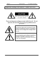
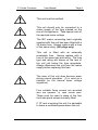
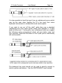
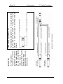
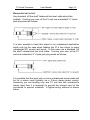
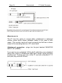
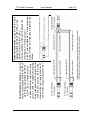
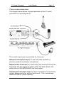
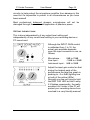
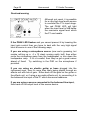
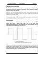
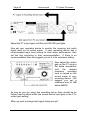
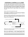
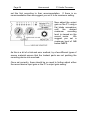
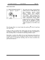
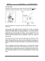
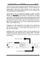
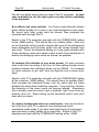
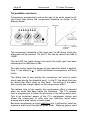
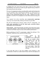
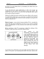
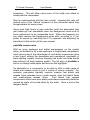
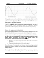
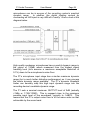
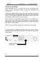
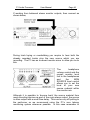
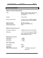
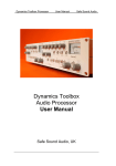
P1 Audio Processor User Manual Safe Sound Audio Model P1 Audio Processor User Manual Safe Sound Audio, UK Page 2 User manual P1 Audio Processor P1 Audio Processor Features Advanced audio compressor with peakride which utilises multiple side-chains allowing the compressor to ‘ride’ the crests of the audio so that control of fast audio peaks, especially vocals, may be as fast as desired whilst release from compression compliments the natural decay of the audio waveform. Exceptionally low levels of ripple distortion. Limiter featuring multi-stage dynamic threshold control which provides a very high degree of overload protection without the undesirable side effects of traditional ‘brick wall’ limiters. The limiter has three side-chains each utilising zero delay ‘look ahead’ dynamic control of limiter threshold. This allows the ‘natural’ limiter threshold to be dynamically adjusted to match the dynamics of the incoming audio signal and provides for very safe control of maximum audio level without the need for ultra fast attack times; all accomplished with 100% analogue processing. Single knob expander with ‘follow-audio’ release time which tracks the natural decay of the audio; useful for post recording noise reduction and adding punch to drum sounds. High quality balanced microphone input using the latest THAT 1510 input stage. Balanced line input. High impedance (1 M) instrument input. Balanced line output offering +21dBu drive capability. Balanced and unbalanced stereo monitor inputs with separate source level control providing zero latency headphone monitoring of the source/replay mix. 100% linear internal mains power supply (throw away those wall warts for good!) P1 Audio Processor User Manual Contents P1 Audio Processor Features Safety Information; READ THIS FIRST Quick Start Guide Audio Connector wiring information Detailed Operational Guide Power on Typical audio connections +48V Phantom Power for microphones Setting the input gain Overload warning Setting up the output gain High pass filter Expander operation peakride compressor operation peakride compressor theory Limiter with dynamic threshold control How the P1 limiter manages dynamic range Answers to some common questions Monitoring facilities Technical Specification Fault finding Customer Care Warranty conditions How to contact us Page 3 Page 2 4 6 10 16 16 17 18 19 20 21 25 26 30 33 36 38 41 44 47 50 52 52 54 Page 4 User manual P1 Audio Processor Important Safety Information : Read this first! There are dangerous voltages present within the unit. Do not open the unit and refer all servicing to qualified service personnel. The lightning flash with arrowhead symbol, within an equilateral triangle, is intended to alert the user to dangerous voltages within the unit. The exclamation point within an equilateral triangle is intended to alert the user to important operating and safety instructions in this user handbook. P1 Audio Processor User Manual Page 5 This unit must be earthed. This unit should only be connected to a mains supply of the type marked on the rear of the appliance. Take special note of the required mains voltage. The IEC mains connecting lead originally supplied with this unit has been fitted with a 3A mains fuse. Always replace with a fuse of the same rating. (UK plugs only) This unit is fitted with an externally accessible fuse. Always replace with a fuse of the same type and rating. The fuse type and rating are shown on the rear of the unit just below the fuse receptacle. Always disconnect the unit from the mains supply before replacing this fuse. The case of this unit does become warm during normal operation. (It is used as a heatsink for the internal linear voltage regulators). Four suitable fixing screws are provided with the optional 19” rack mount ears. These must be used in place of the four front side panel screws normally fitted. If 19” rack mounting this unit it is advisable to leave a ventilated space above the unit. Page 6 User manual P1 Audio Processor Quick Start Guide After reading the important safety information, you may wish to ‘plug and go’. If, at any time, you are in doubt as to the correct operation of the unit, all operational points are covered in detail later in this manual, but as a quick start; BASIC FUNCTIONS The P1 is a mono audio path processor with separate stereo monitoring facility, as shown below; The three audio inputs have separate connectors but only one of these inputs is connected to the main processing chain at any one time. This is controlled by a simple priority system through the actual plugging of the connectors. The balanced LINE input (3 pole ¼” jack plug) will always have the highest priority. P1 Audio Processor User Manual Page 7 The unbalanced INSTRUMENT input (2 pole ¼” jack plug) has priority over the MICROPHONE input. The balanced MICROPHONE input (3 pole XLR plug) has the lowest priority. The connector wiring follows normal audio convention. Details are given later in this manual. Although the three inputs share a common input gain control, the gain range available to each input is different and appropriate to that input; MICROPHONE GAIN INSTRUMENT GAIN LINE INPUT GAIN 0dB to +70dB 0dB to +30dB -10dB to +20dB PHANTOM POWER The microphone input has switchable +48V phantom power suitable for powering most types of studio condenser microphones. ALWAYS CONNECT THE MICROPHONE FIRST BEFORE SWITCHING ON THE +48V otherwise damage to the microphone amplifier is a possibility. In a similar way, always switch off the +48V and wait for 10 seconds before disconnecting the microphone. If you are unsure whether a microphone requires +48V phantom powering always check with the microphone manufacturer first. DON’T GUESS! Most professional BALANCED dynamic microphones will not be damaged through the accidental application of phantom power. Page 8 User manual P1 Audio Processor HI PASS FILTER The switchable high pass filter has a -3dB point at 80Hz and a slope of 18dB per octave. PEAK INDICATOR Lights when the main signal path (before the limiter) comes within 3dB of clipping. EXPANDER Variable threshold expander with a fixed expansion ratio of 1:3, fixed attack time of around 3ms and variable ‘follow-audio’ release time. COMPRESSOR WITH peakride A sophisticated multi side-chain compressor with variable threshold, attack and ratio. ‘Follow-audio’ release time. LED bar graph shows gain reduction in dB’s. LIMITER WITH dynamic threshold control AND OUTPUT LEVEL CONTROL The most sophisticated part of the processing chain but it has no user controls! Full explanation later in the manual, but for now a brief set-up procedure; The limiter is actually the last signal processing element and sits just before the preset output gain control. The limiter threshold is fixed, so for quick set-up; Ensure the expander and compressor are switched OUT of circuit Apply a fixed level test signal (should be a 50% duty square wave) to the line input and adjust the input gain control until the red LIM LED just lights (a suitable test signal is available to download from our web site, www.safesoundaudio.com) P1 Audio Processor User Manual Page 9 Adjust the preset output gain control (screwdriver adjustment) until the desired recording level is shown on your recording device metering; best to allow 1dB below 0dBFS. MAIN OUTPUT The balanced main output is fed via the preset level control described above to a 3 pole balanced ¼” jack labelled ‘LINE OUT (BAL)’. An LED bargraph shows the output level prior to the output gain control. THE MONITORING CHAIN Stereo input designed to be fed from the replay chain of your recording device. Can accept either a single 3 pole ¼” jack for unbalanced stereo connection OR two 3 pole ¼” jacks for balanced stereo connection. Plug as shown on the unit’s rear panel. The monitoring chain feeds the front panel ¼” stereo jack socket best connected to headphones with an impedance of 600 ohms or above. It is safe to connect low impedance headphones but monitor audio quality will degrade. For track laying and overdubbing, it is also possible to mix in a feed of the unit’s main processor path which has it’s own ‘source monitor’ level control. This level control does not affect the processor’s main audio path level. Page 10 User manual P1 Audio Processor Audio Connector wiring information Note: All connector wiring information refers to the cable end connecting to the P1 audio processor unless otherwise stated. BALANCED MICROPHONE INPUT Any standard balanced XLR-3 to XLR-3 microphone cable should be suitable. At the P1 end, use a cable type XLR-3 pin plug wired as follows; Pin 1 = Pin 2 = Pin 3 = screen signal +ve (also called ‘in phase’ or ‘hot’) signal -ve (also called ‘anti-phase’ or ‘cold’) You should not use this input to connect unbalanced high impedance microphones which in any case are normally supplied terminated in a 2-pole ¼” jack plug. BALANCED LINE INPUT Any standard ‘off the shelf’ balanced line level cable should be suitable. These will be typically either jack to jack or jack to XLR depending on the type of equipment you are connecting to the line input. If wiring your own, at the P1 end use a standard ¼” 3-pole jack plug wired as follows; P1 Audio Processor User Manual Page 11 It is also possible to feed this input from an unbalanced source which may be the case when feeding the P1’s line input from some keyboard instruments or unbalanced sound card outputs. If you want to use an ‘off the shelf’ cable then use a standard unbalanced line level cable (guitar cable) with standard ¼” 2-pole jacks at either end. If wiring your own unbalanced cable we suggest the following wiring arrangement which will give better noise and hum rejection. (Note that the sleeve of the 3-pole jack is intentionally left unconnected.) The balanced line input should not be used to directly connect to electric guitars and basses. Use the INSTRUMENT input instead. UNBALANCED INSTRUMENT INPUT Any standard unbalanced ¼” to ¼” 2-pole instrument (guitar) cable should be suitable. If wiring your own use standard ¼” 2-pole jack plugs for both ends wired as follows; INSERT POINT A ‘Y’ type cable is necessary to access the processor’s insert point. The ideal cable type is a twin ‘figure 8’ unbalanced cable. These are available ‘off the shelf’ but if wiring your own, a typical wiring scheme is shown below. Page 12 User manual P1 Audio Processor P1 Audio Processor User Manual Page 13 BALANCED LINE OUTPUT Any standard ‘off the shelf’ balanced line level cable should be suitable. If wiring your own, at the P1 end use a standard ¼” 3-pole jack plug wired as follows; It is also possible to feed this output to an unbalanced destination which may be the case when feeding the P1’s line output to some unbalanced PC sound card inputs. In this case use a standard ‘off the shelf’ unbalanced line level cable. If wiring your own, at the P1 end use a standard ¼” 2-pole jack plug wired as follows; It is possible that the input jack on some unbalanced sound cards will be for a stereo input typically via a 3.5mm stereo jacket socket. Assuming you are feeding only one P1 unit into this soundcard’s stereo input then it is important to ground the unused input of the soundcard to prevent crosstalk. A typical wiring scheme is shown below. Page 14 User manual P1 Audio Processor MONITOR INPUTS The P1 has the option to accept either unbalanced or balanced monitor inputs which allows standard cables to be used in both cases. The monitor inputs will most commonly be fed from a stereo output of the recording device or PC sound card. Unbalanced connection : plugs into the jack labelled ‘MONITOR INPUT L/R (UNBAL)’. If you want to use a standard ‘off the shelf’ cable then use a standard stereo twin ‘figure 8’ unbalanced cable with a single 3-pole jack plug at either end. If wiring your own, at the P1 end use a standard ¼” 3pole jack plug wired as follows; Quasi balanced connection : plugs into the two jacks labelled ‘MONITOR INPUT LEFT (BAL)’ and ‘MONITOR INPUT RIGHT (BAL)’. If feeding from an unbalanced monitor output and wiring your own cable, we suggest the following wiring arrangement which will give better noise and hum rejection. (Note that the sleeves of the two 3-pole jacks at the P1 end are intentionally left unconnected.) Balanced connection : plugs into the two jacks labelled ‘MONITOR INPUT LEFT (BAL)’ and ‘MONITOR INPUT RIGHT (BAL)’. Use two standard ‘off the shelf’ balanced line level cables, or if wiring your own, at the P1 end use standard ¼” 3-pole jack plugs, wiring for either left or right inputs is identical as follows; P1 Audio Processor User Manual Page 15 Page 16 User manual P1 Audio Processor Detailed operational guide POWER ON With the IEC mains cord securely fitted to the rear of the unit, plug the P1 into a suitable mains power source taking special care to ensure the mains voltage is as indicated on the rear panel. Note that a UK 240V AC supply is suitable for powering a unit marked ‘230 VAC’ Check that the front panel green PWR LED is lit. If the PWR LED does not light then immediately disconnect the P1 unit from the mains supply and go to the fault finding section of this user manual. P1 Audio Processor User Manual Page 17 TYPICAL AUDIO CONNECTIONS The diagram below shows a typical application of the P1 audio processor in a recording set-up. Three audio input types are provided for, these are; Balanced microphone input, for use with either dynamic or phantom powered condenser microphones. Balanced line level input, for use with any line level source such as keyboards and the outputs of certain guitar and bass effects units which offer a LOW IMPEDANCE line level output. Unbalanced instrument input, for direct connection of most electric guitars, basses and other electric instruments. This is sometimes called a DI-INPUT (direct injection). Page 18 User manual P1 Audio Processor Although it is possible to connect sources to all the P1 inputs simultaneously, only one will function at any one time; The balanced LINE input (3 pole ¼” jack plug) will always have the highest priority. The unbalanced INSTRUMENT input (2 pole ¼” jack plug) has priority over the MICROPHONE input. The balanced MICROPHONE input (3 pole XLR plug) has the lowest priority. So, for example, if you are using a microphone with the P1 make sure the other two inputs are disconnected! +48V PHANTOM POWER FOR MICROPHONES As a general rule, if you are not sure whether your microphone requires phantom power then don’t press the +48 button. If in doubt check with the microphone manufacturer. For those familiar with this powering method there are only two golden rules; ALWAYS CONNECT THE MICROPHONE TO THE P1 BEFORE SWITCHING ON THE +48V SUPPLY ALWAYS SWITCH OFF THE +48V SUPPLY AND WAIT FOR 10 SECONDS BEFORE DISCONNECTING THE MICROPHONE FROM THE P1 The red +48V LED lights when phantom power is active. Connecting the microphone with the +48V already switched on usually causes an almighty ‘audio thump’ through the unit and is not user friendly to your monitor loudspeakers, your headphones or your ears if you are unlucky to be on the receiving end. The P1 has P1 Audio Processor User Manual Page 19 circuitry to help protect the microphone amplifier from damage in this case but it’s impossible to protect in all circumstances so you have been warned! Most professional balanced dynamic microphones will not be damaged through the accidental application of phantom power. SETTING THE INPUT GAIN This is done independently of any output level setting and independently of any record level setting in your recording device or PC sound card. Although the INPUT GAIN control is calibrated from 1 to 10, the actual gain available depends upon the input connector in use, as follows; Microphone : 0dB to 70dB Line input : -10dB to +20dB Instrument input : 0dB to 30dB Adjust the input gain control so that during the loudest parts of the performance the level bar graph is peaking to –2 or 0dB (lighting one or both of the yellow LEDs). Normally you are not trying to light the RED ‘LIM’ LED but don’t worry if it flashes occasionally; the really excellent ‘dtc’ limiter in the P1 will protect your recording device from overload in a very friendly manner! Page 20 User manual P1 Audio Processor Overload warning Although not usual, it is possible for a very high level audio source to overload the P1’s input stage. The red PEAK LED will light when the input level is 3dB below the maximum signal level which the P1 can handle. If the PEAK LED flashes and you cannot prevent it by lowering the input gain control then you have to deal with the very high signal level at source in one of the following ways; If you are using a microphone source (now we’re guessing, but maybe mik’ing up a 4 x 12 stack running really hot!) then either move the microphone away from the loudspeaker, or turn down the loudspeaker amp. If it’s a vocalist, then they’ve got a great career ahead of them! Try switching in the PAD on the microphone if provided. If you are using an electric guitar or bass plugged into the instrument input, then it’s more than likely being played through an effects unit with lots of gain. Either back off the gain on the guitar or the effects unit, or if using a pro-audio effects unit, try connecting it to the balanced line input of the P1 which has more headroom. If you are using a source connected to the balanced line input, then back off the output level of the source device. P1 Audio Processor User Manual Page 21 SETTING UP THE OUTPUT GAIN The P1 limiter takes care that the maximum audio level through the processing chain is carefully monitoring and controlled without having to adjust any settings. However you do have to adjust the output gain control so that the maximum level from the P1 (after the limiter) matches the desired maximum recording level. There are two ways to do this; by using a test signal, or by trial and error using any dynamic audio source. By test signal If you have access to the internet, and your have access to a PC which can replay sound files, then go to our web site www.safesoundaudio.com and download the recommended set-up test signal which is available as a .wav file. Set-up your normal recording chain as shown below, so that this test signal can be replayed from your PC hard drive from one channel of your sound card, through the P1’s line input and then entered back into one channel of your recording device. Page 22 User manual P1 Audio Processor Adjust the P1’s input gain until the red LIM LED just lights. Now set your recording device to monitor the incoming test audio signal level on its record meter. If your recording device has a recommended input level setting for best audio performance, then set this first according to their recommendation. If there is no recommendation then we suggest you set it to its maximum setting. Now adjust the output gain on the P1 using a flat blade screwdriver until the desired maximum recording level is viewed on the record meter of your recording device. We suggest you set a maximum level of 1dB below 0dBFS. As long as you are using this recording set-up there should be no further need to adjust either the record device input gain or the P1’s output gain setting. Why use such a strange test signal during set-up? P1 Audio Processor User Manual Page 23 The 1kHz square wave signal was chosen to ensure that the recording device metering gives an accurate indication of the PEAK level being fed to its recording input. Many ‘peak’ reading meters still have a finite ‘integration’ time so they will display correctly the peak level of the more usual tone based test signals but under represent the actual peak voltage value of very dynamic audio. The use of a 50% cycle square wave test signal ensures correct peak level indication. SETTING THE OUTPUT GAIN USING ‘REAL AUDIO’ Whilst setting the recording chain levels using the test signal is recommended, it is possible to do it using any source of dynamic audio material either ‘live’ or pre-recorded. Set-up your normal recording chain as shown below, so that the audio source is being fed into the P1 (use the input socket to suit the type of source material) and from the P1’s LINE OUT into one channel of your recording device. Adjust the P1’s input gain until the red LIM LED just lights during the loudest part of the source material. Now set your recording device to monitor the incoming audio signal level on its record meter. If your recording device has a recommended input level setting for best audio performance, then Page 24 User manual P1 Audio Processor set this first according to their recommendation. If there is no recommendation then we suggest you set it to its maximum setting. Now adjust the output gain on the P1 using a flat blade screwdriver until the desired maximum recording level is viewed on the record meter. We suggest you set a maximum level of 1dB below 0dBFS. As this is a bit of a trial and error method, try a few different types of source material ensure that the loudest parts are not pushing the recording device into overload. Once set correctly, there should be no need to further adjust either the record device input gain or the P1’s output gain setting. P1 Audio Processor User Manual Page 25 HIGH PASS FILTER The high pass filter (sometimes called a low cut filter) affects only low frequency sounds below what’s called the turnover frequency which in the P1’s filter is set to 80Hz. When switched into circuit, it will reduce the level of all audio components below 80Hz progressively at a rate of 18dB per octave, so for example a 30Hz tone would be reduced in level by 18dB compared to the 60Hz tone level. The HI pass filter is in circuit when the yellow two main uses; led is lit and has Firstly, to filter out mains hum which gets into the recording chain, sometimes caused by the use of unbalanced audio connections in the recording chain, or because the earthing scheme is poor. Secondly, to reduce the effect of very low frequency noise pick up through microphones and microphone stands (could be rumble from traffic noise) or microphone handling noise for those vocalists who just have to hold on! Page 26 User manual P1 Audio Processor THE EXPANDER Expanders reduce audio gain when the audio level falls below the expander threshold setting as shown in the diagram below; The P1 expander is a simple to use with a single knob to set the threshold. As the audio input falls below the threshold, its gain is reduced progressively from 0dB (no gain change) up to a maximum gain reduction of 20dB (called the expander depth). So loud sounds are unaffected but quiet sounds get quieter. This is expansion of the audio’s dynamic range below the expander threshold. The red ACTIVE LED lights whenever any expansion of the audio signal is taking place. The expansion ratio is how much the audio gain is reduced as it falls below the threshold point. The P1 uses a fixed ratio of around 1:3 (with a soft knee at the threshold point) so that (below the threshold) for every 1dB that the input level drops, the output level will drop by 3dB. The P1 expander attack time is approx. 3ms. This is the time it takes for the expander to go from the full 20dB gain reduction to no gain reduction as the input audio level rises towards the threshold point. It’s fast enough so that the front end of a vocal phrase or note is not lost but slow enough so as not to cause distortion in slowly rising audio. P1 Audio Processor User Manual Page 27 Hold time is how long the expander waits before operating when the input level falls below the threshold setting. The P1’s hold time is programmed to follow the natural dynamics of the audio signal. Short duration audio phrases have a short hold time whereas long audio phrases have a longer hold time. Release time is the time it takes the expander to reduce the audio gain as the input level falls below the threshold setting. The P1’s release time is programmed to follow the dynamics of the falling audio signal. So a fast falling input signal, such as the tail of a drum beat will set a fast release time and a slow falling signal, such as the decaying note of a sustain guitar note will set a slow release time. In this way the P1 release is able to track the natural decay of the audio signal. The release time in the P1 has a programmed range from 90ms (fast) to 900ms (slow). Expanders are often compared to noise gates, but in general use expanders are more natural sounding because their control of audio gain is directly related to the audio signal characteristic which is not the case in a noise gate. Expanders have a wide variety of uses in music recording but we recommend they are normally used on audio material which has already been recorded rather than when recording ‘live’. To do this, connect your P1 as an effects device in your track mix down chain as shown below. Page 28 User manual P1 Audio Processor We will now detail some common uses of the P1 expander. In each case remember to set the input gain correctly before switching in the expander. As a effects unit noise reducer : You have a really favourite classic guitar effects peddle but it has a very high background noise level. So record your killer guitar track as normal, then playback the recorded track through the P1. Switch in the P1’s expander and start with the THRESHOLD setting at the -60dB setting. This should have no audible affect. Now turn up the threshold control just far enough that most of the background noise disappears and the killer guitar solo still comes through loud and clear. Check the threshold setting on a few guitar phrases with slowly decaying notes and maybe make a final small adjustment to ensure the decaying notes sound as ‘natural’ as possible. To improve the isolation of one drum sound; It’s quite common when multi-track recording a full drum kit that getting enough sound isolation between the individual tracks can be difficult. For example it’s quite common to get ‘spill’ from the high-hat onto a snare drum track. Switch in the P1’s expander and start with the THRESHOLD setting at the minimum –60dB setting. This should have no audible effect. Now increase the threshold slowly until the extra high hat beats between the snare drum beats are removed. If you push too far then the dynamics of the snare sound will become altered. Sometimes this is actually used as a way to get a synthetic ‘tight’ sound from an acoustic drum kit. Keep turning up the threshold control and you’ll hear what we mean. To remove background noise on vocal tracks; this may be due to fan noise from your PC or general room background noise, sometimes made worse if you have used high levels of compressor gain reduction to really tighten up a vocal track. Switch in the P1’s expander and start with the THRESHOLD setting at the –60dB P1 Audio Processor User Manual Page 29 setting. This should have no audible affect. Now turn up the threshold control slowly so you lose as much as the background noise as possible without losing the natural decay of the vocal phrases. Make sure you turn up the threshold control far enough so that the background noise doesn’t drift back during very quiet or silent passages. Occasionally, there are times when you may want to use the expander when recording; for example; You are doing some ‘guide track’ vocal recording through the P1 into an absolutely state of the art super fast PC which generates fan noise of a similar level to an F16 fighter jet! And no amount of microphone placement in your studio makes it much better. Whilst you could strip out the worst of the background noise after recording using the P1 you just want a quick guide vocal track and the background noise in the headphones is getting on your nerves, so; Connect the P1 in the normal way for recording new source material. Switch in the P1’s expander and start with the THRESHOLD setting at the –60dB setting. This should have no audio affect. Now turn up the threshold control just far enough that most of the background noise disappears and the vocals still come through clearly. Page 30 User manual P1 Audio Processor THE peakride COMPRESSOR Compressors progressively reduce the gain of an audio signal as its input level rises above the compressor threshold as shown in the diagram below; The compressor threshold is the level point in dB above which the audio gain will be reduced. On the P1 this can be varied from 0dB to -40dB. The red LED bar graph shows how much the audio gain has been reduced and is calibrated in dBs. The ratio control varies the degree of gain reduction which is applied, from 1:1 (no effect) to : 1 which will make the compressor act like a limiter. The attack time is how quickly the compressor will react to audio which rises above the threshold point. In the P1 the attack time can be varied from 60ms (slow) to 1ms (fast). The setting of the attack time usually has a large impact on the compression effect. The release time is how quickly the compression effect is removed when the audio falls back below the threshold. The P1’s release time is programmed to follow the dynamics of the falling audio level. This is an important aspect of the P1’s compressor design and allows the compressor to offer very low distortion levels when working with a wide variety of audio types. Because compression is a gain reduction tool, it will tend to lower the maximum audio level through the audio chain. Make-up gain is used P1 Audio Processor User Manual Page 31 to replace this ‘lost’ level and in the case of the P1 this is done automatically; the amount of make-up gain applied being related to the threshold and ratio settings. The use of compression when recording both vocals and instruments is a very powerful way of achieving the desired ‘live’ sound and so is often used at the track laying stage as it can actually improve the quality of the performance given by the artist. However it is also possible to use the P1’s compressor as an effects device during mix down. As a general rule when recording; use compression sparingly unless you are intentionally seeking a dramatic sound effect. We will now detail some common uses of the P1 compressor. In each case remember to set the input gain correctly before switching in the compressor. Vocal tracks : Most commercially recorded vocal tracks have some compression applied. This is often done to help the vocal sit properly in the mix and it also helps to even out the artist’s performance. Before switching in the P1’s compressor, adjust the settings of the threshold, attack and ratio controls as shown below. Now switch in the compressor. As the threshold is set to 0dB there will be no audible effect. Now slowly turn up the threshold control until the gain reduction meter is peaking between 4dB and 6dB. This should be enough for most vocals. Now let’s turn to the attack and ratio settings. If you find that some of the first syllable vocal phrasing is still uncontrolled or that the vocalist tends to lean into the microphone at Page 32 User manual P1 Audio Processor the start of a vocal phrase then try decreasing the attack time (turn the knob clockwise). If you feel that the vocal performance is still a bit uneven, try increasing the ratio control until you get a more even result. Be careful not to go too far or you will kill all the dramatic effect which the vocalist is trying to achieve. Altering the attack and ratio controls has some effect on the amount of compression achieved so you may have to readjust the threshold control if you find the gain reduction meter reading is moving too far from the desired level. Electric basses : many electric basses whether DI’d or recorded by mik’ing the bass amp loudspeaker can have a very uneven recorded sound. Compression is a very common and useful way to deal with this problem. Before switching in the P1’s compressor, adjust the settings of the threshold, attack and ratio controls as shown below. Now switch in the compressor. As the threshold is set to 0dB there will be no audio effect. Now slowly turn up the threshold control until the gain reduction meter is peaking at around 8dB. This should be enough for most bass recording but don’t be afraid to use more if it gives a tighter sound. Now let’s turn to the attack and ratio settings. If you feel you’ve achieved a nice even bass sound but that it’s lost some of it’s punch, try increasing the attack time (turn control anti- P1 Audio Processor User Manual Page 33 clockwise). This will allow some more of the initial note attack to sneak past the compressor. Now try experimenting with the ratio control. Lowering the ratio will restore more of the ‘natural’ dynamics of the instrument which may be appropriate for some mixes. Using such high levels of gain reduction (with the associated high gain make-up) can sometimes raise the background noise level of some instruments to an undesirable level. When this happens you can either remove the background noise after recording or if you prefer at source by switching the P1’s expander and adjusting as described in that section of the user manual. peakride compression With so many analogue and digital compressors on the market today, we decided to try a new approach to single band compression which gives most of the advantages of multi-band compressors (plus a few more!) without the downsides and operational complexity of band splitting (usually involves chopping the audio into three bands then putting it all back together again!) The full story of peakride is told in our design white paper but here are the highlights; It’s desirable for a compressor to be able to offer a wide range of attack and release times to suit a variety of source material. For example, percussion typically requires medium fast attack and release times whereas some vocals require quite fast attack times and medium/slow release times. Fast attack, fast release compressors often have poor audio performance especially distortion caused by ripple of the side-chain by the audio. Have a look at the diagram below; Page 34 User manual P1 Audio Processor Many instruments and vocalists have a natural vibrato which finds it’s way into the compressor control side-chain causing the gain to move up and down in sympathy. This is extremely undesirable and causes high levels of non-linear distortion. The P1’s peakride design overcomes these problems by the use of three separate control side-chains which act in the time domain (rather than in the frequency domain of a multi-band compressor). Above the compressor’s threshold; Short duration audio bursts (such as percussion) get processed with the fast attack fast release compression which they tend to require. Longer duration audio bursts get processed with an initial attack time as set on the front panel and an initial short release time but; as the audio sample continues, the attack and release times are progressively lengthened according to two factors; The time the audio sample has been above the compressor threshold The continuing dynamics of the audio signal Even the use of a manually set release time (requiring constant adjustment) cannot achieve the low levels of distortion which the P1 design delivers. A second problem with traditional fast attack compressor designs is caused by a misunderstanding between the desirability for fast P1 Audio Processor User Manual Page 35 attack, especially to provide adequate control of certain vocal styles, and the usual consequence that the whole vocal phrase then suffers from over compression. It is often difficult to achieve the attack speed without the undesirable over compression. The P1 compressor achieves this by altering the ratio of the compressor dynamically. So you can set an average compression ratio on the front panel control but the actual delivered ratio will alter to suit the dynamics of the audio as it rises above the threshold level. These principles are at the heart of the peakride design and are achieved by mixing the three compressor side-chains at different levels and with different compression ratios. In effect, the compressor side-chain is able to ride the peaks of the audio, reacting quickly but smoothly to fast attack peaks, and then able to track the dynamics of the continuing audio till it falls below the threshold point. Page 36 User manual P1 Audio Processor The P1 limiter with dynamic threshold control Considering that almost half of the processing power in the P1 is dedicated to the limiter, it doesn’t exactly have a high profile on the front control panel, so what’s it all about? Let’s start with the basics; All digital recording systems have a maximum signal level which they can handle. If you go above this level then digital audio clipping will result and it sounds truly awful. Not only are the peaks and troughs of the audio waveform clipped (as shown below) but a second problem called aliasing distortion can occur which is even worse. A limiter allows the maximum audio level to be fixed to a level set by the limiter threshold. So any audio which comes in above that threshold is gain reduced to be no higher than the threshold setting. Have a look at the ‘before and after’ audio waveforms below. Note that some of the audio peaks which were above the limiter threshold are not, after limiting, exactly on the threshold but below. This is due to the release time of a limiter and is a necessary and desirable limiter characteristic. P1 Audio Processor User Manual Page 37 But can’t I just record in such a way that this maximum audio level is never reached? In theory, yes you can; if you are very careful and record well below the maximum permitted level of your recording system; but as so commonly happens, you set up the levels carefully during rehearsal but when the actual recording takes place, the vocalist has turned from shy retiring folk singer to the rock legend from hell! And the once in a lifetime performance is ruined by digital clipping which is almost impossible to repair even with the might of software based audio processing tools. So it’s much better to be safe than sorry, and after all we are Safe Sound Audio! The second issue is audio noise and distortion. Let’s assume you leave 12dB of spare headroom for unexpected vocal excesses. So you are setting the MAXIMUM recording level at -12dB during rehearsals. Let’s also assume you are using a typical affordable 24bit recording system which will present a usable dynamic range of around 100dB RMS (around106dB A-weighted). So now our safe usable dynamic range has been reduced from 100dB (-12dB headroom) to 88dB. Well it’s not too bad and it is in the same ballpark as the dynamic range of commercial CDs. Less well known is that the wonderful distortion figures quoted by digital recording systems, typically 0.003% or better, are only achieved when every single bit of the front end A/D converter is Page 38 User manual P1 Audio Processor being exercised and this only happens when you pump in the very highest audio level which the converter will accept before digital clipping. This level is called 0dBFS. So, allowing our 12dB safety margin, a quiet vocal phrase may only be peaking 20dB below this maximum safe level (down at -32dBFS). In the analogue world this will makes no practical difference to the achievable distortion, but in the digital world, lower levels into the A/D means less bits representing the audio means more distortion. Typically a -32dBFS signal will achieve a distortion performance of around 0.01%. Not quite the dazzling figure quoted in the sound card spec, is it? Once we get down to –60dBFS distortion degrades to around 0.3%. So there are audio performance advantages in getting a decent level of audio into 24 bit digital recording systems. If your working 16 bit then it’s even more critical. How the P1 limiter manages dynamic range Despite the claims of many soundcard and A/D chip manufacturers, the usable dynamic range of most affordable 24 bit soundcards is around 100dB. We define this as; ‘the difference in dB’s, measured RMS unweighted, between the maximum signal which the soundcard can handle, called 0dBFS, and the minimum tone level which is audible (not necessarily the same level as the soundcard’s noise floor).’ Most soundcard manufacturers quote dynamic range in dBA which is a weighted measuring scale taking into account the sensitivity of the ear to different frequencies. It also happens to be a way of quoting a higher dynamic range figure! Soundcard manufacturers also tend to claim a higher dynamic range, claiming that the ear can detect sound content which is buried far into the noise floor. The use of frequency weighted digital dither has made such claims very fashionable but many independent reviewers have questioned their validity. It is desirable to manage dynamic range when recording because the available dynamic range from recording sources such as P1 Audio Processor User Manual Page 39 microphones can be in excess of the recording system’s practical dynamic range. In addition, the digital clipping caused by overloading an A/D input is very difficult to rectify. Have a look at the diagram below. High quality condenser microphones have a useful dynamic range in the region of 120dB, where measured from the highest signal handling level (let’s assume a maximum acceptable distortion of 0.1%) down to the microphone’s noise floor. The P1’s microphone input stage has a similar maximum dynamic range (but a much better distortion performance) so it can process the whole dynamic range available. The P1’s dynamic threshold limiter can sensibly map this high input dynamic range into the recording device’s available dynamic range. The P1 sets a nominal maximum OUTPUT level of 0dB (actually +7dBu or 1.735V RMS). This is mapped close to the maximum possible input level of the soundcard, typically to -1dBFS. This means that the P1’s output noise floor is of the same order as that achievable by the sound card. Page 40 User manual P1 Audio Processor However the P1 has three very useful ways to manage the high input dynamic range available; It has a very high quality dynamically variable threshold limiter to protect the soundcard against unexpectedly high levels which would lead to digital clipping. It has an additional 14dB of input headroom so that unexpected high input levels do not level clip within the P1. It has an extended input noise floor when the microphone amplifier is operating at low gain (i.e. when the microphone is delivering very high input levels and so its highest dynamic range). The same general principles apply to the balanced line and unbalanced instrument inputs. P1 Audio Processor User Manual Page 41 Answers to some common questions; Q. Why don’t 24 bit soundcards achieve their theoretical 144dB dynamic range in practice? A. The highest audio signal level which most 24 bit A/D chips can handle is around +7dBu limited by the +5V supply voltage which these chips are designed to run from (not to be confused with the soundcard’s maximum input level which is often much higher but this is simply fed through an analogue level attenuator to the actual A/D chip). The lowest audio signal level which an A/D chip can resolve is limited by two main factors; The noise floor of the analogue input circuitry. The problems of sampling very low voltage levels accurately. These last two factors usually determine the level at which the dither noise is added to the digitally sampled audio signal and this in turn sets the soundcard’s noise floor. So there are practical issues which limit both the maximum and minimum signal level which the A/D converter can work with and these limit the dynamic range achievable in practice. Q. Why don’t you offer a higher output dynamic range in the P1 processor? A. There are two factors which set the output dynamic range of the P1; Remembering that the P1’s maximum output is limited to prevent digital clipping of your recording device; Increasing the limiter’s natural threshold above 0db (+7dBu) would decrease the available input headroom (set at 14dB) as we worked closer and closer to the P1’s own maximum Page 42 User manual P1 Audio Processor signal handling limit of +21dBu. There wouldn’t be much point in protecting the digital recording chain if we could accidentally clip the P1’s own circuitry. The P1’s maximum output level is also set to achieve the best distortion performance through the THAT VCA chip which is at the very heart of the limiter. Lowest distortion is achieved at or below +2dBu and is still very good at the +7dBu limit we have set. Q. You talk about levels in dB and in dBu. difference? And what about dBFS? What’s the A. dB’s are a relative measure of level, e.g. -6dB is 6dB lower than 0dB. dBu is an absolute measure of level within an analogue system. 0dBu can be measured as a voltage and is always 0.775 volts RMS. 0dBFS is the maximum possible level of a digital audio system. Q. What is so useful about using dynamic threshold control in the P1’s limiter design? A. For a detailed answer, have a read of the P1 technical white paper, but in summary; In order to fully protect a digital recording system from digital clipping, it is necessary to limit the maximum signal fed to the recording system. However it sounds very unnatural to instantaneously reduce the gain of a signal chain in order to stop the overload occurring (this is what many traditional limiters do). Sudden gain changes can introduce clicks into the audio and also cause high levels of what’s called ripple distortion. The P1’s limiter uses three separate control side-chains which vary the limiter threshold by up to 3dB below the P1 Audio Processor User Manual Page 43 ‘natural’ threshold (which we call 0dB) and this allows the limiter to use a much gentler control side-chain to ensure that the maximum permitted level is not exceeded. As the threshold is set according the dynamics of the input audio, it allows a higher useful dynamic range to be passed on to the recording device than traditional limiter designs and at much lower levels of distortion. Page 44 User manual P1 Audio Processor The monitoring facilities We’ve designed the P1 to provide the kind of monitoring set-up which is most commonly required during track recording and overdubbing. If you have enough replay outputs from your recording device then one stereo output of your recording device will normally be dedicated to your main monitor loudspeakers and a second stereo output will be available to feed to the P1’s monitor inputs. If you have only a single stereo output from your recording device then you can either work solely using headphone monitoring during track laying, or use a split lead to feed both your monitor power amp and the P1’s monitor inputs. The P1 can accept either unbalanced or balanced monitor inputs. If working from an unbalanced single stereo jack monitor output, possibly a single 3.5mm stereo jack from a PC card, then connect as shown below; P1 Audio Processor User Manual Page 45 If working from balanced stereo monitor outputs, then connect as shown below; During track laying or overdubbing you require to hear both the already recorded tracks plus the new source which you are recording. The P1 has an on-board monitor mixer to allow you to do this. The headphone volume control sets the overall monitor level fed to the headphones and the MON SOURCE level control allows you to set the level of your new source material within the monitor mix. Although it is possible to ‘bounce back’ the source material from most recording devices as part of the main stereo output, the source is often output with a small time delay. This can be very off-putting to the performer so we recommend using the P1’s zero latency monitoring system whenever possible. In this case remember to Page 46 User manual P1 Audio Processor mute the feed of the record input from the recording devices monitoring output. The P1 is capable of generating high monitor levels so always switch the headphone level control to minimum when connecting headphones then turn up the level slowly to the achieve the desired monitoring level. Monitoring at high levels for sustained periods is not advisable. P1 Audio Processor User Manual Page 47 Technical Specification MODEL P1 AUDIO PROCESSOR Size : 223mm wide by 44mm high (1U) by 225mm deep (excluding cable connectors) Weight : 1.8kg (4lbs) Power requirements : AC power to the voltage indicated on the rear panel 10%, 50/60 Hz. Mains Plug fuse : Rear panel fuse : Power consumption : 3A (UK plugs only) 20mm fuse, 250mA 250V 15W MAIN PROCESSOR AUDIO PATH Frequency response : -0.5dB points at 15Hz and 55kHz Distortion : < 0.01% at 1kHz (typically 0.008%) main signal path working at 0dBu, limiter always in circuit. MAXIMUM INPUT LEVELS; Microphone : Line input : Instrument : +11dBu +21dBu +11dBu INPUT IMPEDANCES; Microphone : Line input : Instrument : PRE-LIMITER HEADROOM : 2k4 > 10k 1M +14dB above the limiter threshold. Page 48 User manual P1 Audio Processor EQUIVALENT INPUT NOISE FIGURES; Microphone : Line input : Instrument: 128dB (max gain with 150 ohms source) 100dB (unity gain) 105dB (max gain) BALANCED LINE OUTPUT Output noise : -93dBu RMS unweighted, measured 22Hz to 22kHz -95dBu RMS A-weighted, measured 22Hz to 22kHz Maximum Output Level (post limiter) : > +21dBu Output impedance : 50 INPUT GAIN RANGES Microphone input : Line input : Instrument input : 0dB to +70dB -10dB to +20dB 0dB to 30dB EXPANDER Threshold range : -60dB to 0dB Attack time : 3ms Release time : variable between 90ms and 900ms (tracks the natural audio decay) Ratio : 1:3 with a small degree of ‘soft knee’ at the threshold point P1 Audio Processor User Manual Page 49 PEAKRIDE COMPRESSOR Threshold range : 0dB to -40dB Attack time range : 60ms to 1ms Release time : variable from 90ms to 500ms (tracks the natural audio decay). Ratio : 1:1 to INF:1 Make-up gain : automatically set in proportion to the threshold and ratio settings. Gain reduction meter : calibrated in dBs. DYNAMIC THRESHOLD CONTROL LIMITER Threshold : fixed internally to +7dBu Attack time : fastest ‘natural’ is 5ms augmented by the ‘look ahead’ dynamic threshold control. Ability to control peak level : will control overshoot to within 0.5dB for a very fast rise time waveform (30us) set for 6dB of overload. MONITOR OUTPUT For highest quality monitoring, use headphones with an impedance of 600 ohms or above. Use of low impedance headphones is possible however, expect reduced audio quality. Page 50 User manual P1 Audio Processor Fault finding Problem : Green Power LED does not light when unit is connected to the power source. Checks : Is there any visible or audible sign of physical damage to the unit? If so, immediately disconnect the unit from the mains supply and connect Safe Sound Audio for assistance. Is the power socket actually switched on? Is the power source the same voltage as indicated on the unit’s rear panel? (NOTE: a 240V AC supply is suitable for powering a unit marked for 230V AC) After disconnecting the unit from the mains supply, check both the mains plug fuse and the rear panel fuse. If either of these has blown then replace with the correct type of fuse and then reconnect the unit to the mains power supply. If the green power LED still does not light disconnect the unit from the mains supply and contact Safe Sound Audio for assistance. Problem : I have read the user manual but I am still unsure which type of cable to connect the P1 to my recording device. Advice : First you need to establish whether your recording device uses unbalanced or balanced audio connections. Then try buying the recommended ‘off the shelf’ cable type recommend in this user manual. If you are still having problems then contact us for further advice, preferably by e-mail telling us the make and model of recording device you are using. P1 Audio Processor User Manual Page 51 Problem : I seem to be having problems setting up the output level control on the P1 to match my recording device to give a consistent result. Advice : Make sure that the expander and compressor on the P1 are switched OFF when your are setting output level control. Problem : I am connecting the P1 to another balanced audio device but I am still experiencing higher than desirable levels of hum. Advice : There is a possibility of earth loops if both ends of the balanced cable screen are connected to ground through different pieces of equipment. You can try disconnecting the cable screen at the end from which the audio signal is being sent from see if this provides a solution. We don’t recommend this as a normal way to wire balanced cables for two reasons; 1. Having the cable screen earthed at one end may turn the screen into a long antenna which can then pick up all sorts of nasty air borne noise signals. This is a very common problem especially if you disconnect the screen from the audio receiving end. 2. The cable then becomes non standard which can create confusion in use and cause the wrong end of the screen to be disconnected. Never disconnect the P1’s mains plug earth connection in an attempt to solve a hum loop problem. It is dangerous and compromises the electrical safety of the unit. Page 52 User manual P1 Audio Processor Customer Care If you have a problem with the unit and suspect it is faulty, then first follow the guidelines in this manual for set-up, operation and fault finding tips. If you still cannot get the unit to function as you expect then contact Safe Sound Audio for advice and if necessary we will issue a Returns Authorisation Number prior to you returning the unit to us for servicing. Under no circumstances attempt any repair by opening up the unit. Always refer any servicing work to Safe Sound Audio or a suitably qualified technician. Warranty Conditions Safe Sound Audio provides a 12 month warranty from the purchase date for this product according to the following conditions; This warranty is not transferable and applies only to the original purchaser of the unit. If the unit should become faulty, then contact Safe Sound Audio for a Return Authorisation Number. No items will be accepted for warranty repair without this authorisation number. You must be able to produce proof of the purchase date. If the returned unit should prove faulty then, at Safe Sound Audio’s choice, we will either repair or replace the unit. The customer is responsible for the cost of sending the unit back to Safe Sound Audio including insurance of the unit during shipping. P1 Audio Processor User Manual Page 53 Safe Sound Audio will be responsible for the cost of shipping the repaired or replaced unit back to the customer including insurance of the unit during shipping. The warranty will be void if the unit has; Suffered physical damage. Has been connected to an incorrect source of mains power. Has been damaged due to liquid spillage. Safe Sound Audio shall not be liable for any special or consequential damages resulting from the use of this product. Page 54 User manual P1 Audio Processor How to contact us By post : Safe Sound Audio 47 Broadgate Lane Horsforth Leeds West Yorkshire LS18 4AG UK Callers strictly by appointment By telephone : +44 (0)7866 574 522 By e-mail : [email protected] On the web : www.safesoundaudio.co.uk Safe Sound Audio reserves the right to make changes and improvements to the design of this product without notice. P1 Audio Processor Notes User Manual Page 55 Page 56 User manual © Safe Sound Audio 2010 P1 Audio Processor