1
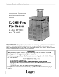
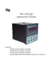
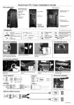
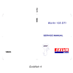
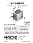
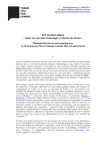
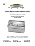
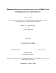
A Testbed for Experiments with Sensor/Actuator Networks
Mohammed Rahimi
Rohit Mediratta
Karthik Dantu
Gaurav S. Sukhatme
Robotic Embedded Systems Laboratory
Computer Science Department
University of Southern California
Los Angeles, CA 90089-0781, USA
mhr mediratt dantu gaurav @.usc.edu
Abstract
We describe a table-top testbed for experiments in mobile sensor networks. The testbed includes static nodes
as well as robotic mobile nodes. The static beacon nodes
are used for localization and multihop network setup. The
static snooper nodes serve the purpose of debugging and
visualizing the experiment at a later time. The snoopers
passively listen to packets. Ground truth is provided by
an overhead vision system, and the data logged by the
snoopers are replayed to evaluate/debug the network using NAM.
Keywords: sensor network, sensor/actuator network,
testbed
1 Introduction
We describe the design of a planar testbed (Figure 1) for
experiments with sensor/actuator networks on the benchtop. The testbed allows experimenters to populate the
benchtop with small (upto 25 nodes) multi-hop wireless
networks (typically upto 3 hops) of extreme embedded devices [1]. In addition, we have roboticized some of the
sensor nodes such that they can move about on the testbed
and autonomously re-position themselves [2]. An overhead camera system [3] provides ground truth for localization, and a set of snooper nodes capture network traffic
for offline analysis. Since the setup is indoors we can easily control the illumination intensity (for experiments with
the light sensors on the nodes), the locations of the nodes,
camera calibration, and the like. The testbed is logically
partitioned into a structured grid of 32 squares, with each
square being 1 square foot in area. We describe the testbed
setup in the following four sections.
Beacons: the beacons are evenly distributed in the
environment and know their x,y coordinates. These
beacon nodes are used for localization as well as for
multihop network setup.
Snoopers: these nodes serve the purpose of debugging and visualizing the experiment at a later time.
The snoopers passively listen to packets.
Overhead vision: ground truth is provided by the vision system using mezzanine, an overhead camera
system looking down onto the testbed.
Post Processing: the data logged by the snoopers are
replayed to evaluate/debug the network using NAM.
The testbed (Figure 1) is a 8’x 4’ tabletop bound by
a wooden fence 3/4” high. The tabletop is colored white
to aid the ground truth system in identifying the robots
based on color coding. The tabletop stands on top of three
columns 40” high.
2 Beacons
The beacons are built around the UC Berkeley Rene
mote [1]. The beacons are evenly spread over the testbed
and serve to make up the static part of the network. Each
beacon has one Atmega 163L microcontroller based mote,
one Programming board and a Nickel-coated Cover for RF
shielding to minimize interference and multi-path effects.
To ensure similar power levels for all beacons in the network we provide power using a 3V 500mA DC adapter.
The beacons are programmed using Tiny OS [4]; a
component-based small operating system. Each beacon
executes a routing component as well as a localization
component.
2.1
P ROGRAMMING B OARD
The programming board 2 was fabricated specially to
allow us to package it inside a case to minimize RF interference. The programming board is similar to the programming board from Berkeley, and differs only in the
physical layout. As shown in 2 the programming board
contains a DB25 male connector for programming any
mote on the board. It also contains a DB9 female connector to read data over the serial port which helps in debugging.
The programming board was manufactured by Crossbow Technologies ??.
Figure 1: The testbed.
Company
Crossbow Technologies
MG Chemicals
Antenna Factor
Radioshack
Gold Star Technologies
Product
Super Shield Conductive Coating 841-340g
JJB Series Permanent 1/4 Wave
3vDC/500mA Regulated AC-to-DC Adapter 273-1756
RocketPort Multiport Serial PCI Octa card 95850-5
URL
www.xbow.com
www.mgchemicals.com
www.antennafactor.com
www.radioshack.com
www.gstmc.com
Phone
408-965-3300
800-201-8822
800-489-1634
800-THE-SHACK
800-567-2764
Figure 2: Manufacturer contacts
Figure 4: The case.
Figure 3: The programming board.
2.2
AT M EGA 163 MOTES
The ATMEL Atmega 163 mote is a 4 Mhz low power
microcontroller based mote. It contains a 16KB flash instruction memory, 512 bytes of SRAM, a 256 KB of EEPROM as secondary storage. There is also a RFM TR1000
radio for communication. More details and hardware description can be found at
http://webs.cs.berkeley.edu/tos
2.3
C ASING
The beacons are placed inside special cases 3 to minimize Radio Frequency (RF) interference. These cases
have interfaces for programming the motes and for debugging over the serial connection. The casing also has
a power jack, to enable us to maintain constant power levels using a DC power adapter. The case is essentially the
outer cover of a DB25 to DB 9 converter available off the
shelf from any electronics shop. Our programming board
was designed with the casing already available to us. We
had to drill holes in the casing to allow us to provide power
to the programming board as well as to allow space for the
antenna to stick out.
To minimize RF interference and multi-path fading effects we coated our casing with conductive Nickel coating ??. This conducting coat absorbs small traces of RF
thus greatly reducing multipath fading effects. One to two
mil coating provides 40db-50db shielding across a frequency range of 5 to 1800 Mhz. Since the coating is electrically conducting, we painted the casing on the inside, to
prevent any possibility of a short circuit.
We purchased monopole antennae from Antenna Factor ??. The tiny JJB series of antenna is only 7mm in diameter and can be soldered directly onto the PCB. It allows us
minimize directional effects of unevenly shaped monopole
antennae. The antenna works for the 902-928Mhz frequency range.
To maintain a homogeneous setup of calibrated static
nodes, it is important to ensure that all nodes have the
same power levels available to them at all times. It can
be easily shown [6] that the communication capabilities of
any mote is greatly hampered by reducing power levels.
We power all our beacons with 3V 500mA regulated DC
power adaptors purchased from Radioshack ??.
3 Snoopers
Our testbed has snooper nodes which are placed at
specific places to sniff the packets being exchanged on
the testbed. Snoopers are used for debugging, localization service, (the vision system is used for localization
ground truthing) as well as replaying the network packet
exchanges at a later time using our NAM post processing
tool. Each snooper executes the GENERIC BASE component [4] and has a serial cable connected to one of the port
on an 8 port serial card on a central machine (a PC next to
the testbed). The serial card is polled on this machine to
generate a dump (log) of almost all packets exchanged on
the testbed. We ensure that packets, which may be read by
multiple snoopers simultaneously, do not get logged multiple times. To undertake duplicate suppression we maintain a log of upto the last ten packets that were logged.
Whenever a new packet is being logged into the log file, it
is first checked against the last ten packets to ascertain that
the packet was not already logged by some other snooper.
The snooping system is thus composed of
Programming boards
Atmel 8535 motes
Comtrol Rocketport 8 port serial card.
Serial Extension cables.
3.1
P ROGRAMMING
BOARDS
The programming board contains a DB25 male connector for programming any mote on the board. It also
contains a UART chip and a DB9 female connector to
read data over the serial port which helps in debugging.
The programming board was manufactured by Crossbow
Technologies ??.
3.2
ATMEL 8535 MOTES
The ATMEL 8535 mote is a 4 mhz low power microcontroller based mote. It contains a 8KB flash instruction
memory, 512 bytes of SRAM, a 512 bytes of EEPROM as
secondary storage. There is also a RFM TR1000 radio for
communication for upto 10kbps data rate. More details
and hardware description can be found at
http://webs.cs.berkeley.edu/tos
3.3
C OMTROL ROCKETPORT 8
PORT
PCI
SERIAL
CARD
The card uses a 36Mhz ASIC (Application Specific Integrated Circuit) that enables the RocketPort ?? to transmit and receive data at rates up to 921 Kbps full duplex
across all ports simultaneously. It provides us with 8 ports
to which the snoopers communicate, to send the data they
snoop. The data from all ports are timestamped and logged
into the same log file.
3.4
S ERIAL E XTENSION
CABLES
The serial extension cables are used to connect the DB9
serial interface on the programming boards to the serial
DB9 interface on the Y cable of the Rocketport PCI serial
card.
4 Vision System
The vision system is used as ground truth for the localization component executing on the Robomote. The
vision system returns accurate x,y coordinates as well as
orientation of the robots. We used Mezzanine1 [3] for our
vision system. The system is freely available at playerstage.sourceforge.net
Our camera is placed directly over the testbed. A wide
angled camera provides us with a warped picture of the
testbed, however Mezzanine is equipped with a dewarping
utility to remove any dewarping effects.
4.1
C AMERA
We used a regular off the shelf webcam with a wide angled lens. The camera was mounted on the roof, 6’ above
the testbed, looking down on the testbed. It was attached
to the roof using Velcro. This setup is prone to aging (camera angle looking down will change over time) but Mezzanine provides an easy GUI based calibration tool which
override any loss of calibration due to movement of either
the testbed or the camera. The camera provides an output
in YUV space in the NTSC format onto the composite signal pin of the frame grabber. The camera is powered by a
5V 1000mA DC adaptor.
4.2
F RAME G RABBER
We use a 640x480 interlaced NTSC PCI framegrabber.
The camera’s output serves as a composite input for the
framegrabber. The framegrabber captures 30 frames per
second. However we use only 1 in 3 frames for an acceptable user interface display. The frame grabber is queried
by Mezannine which processes the captured frames.
5 Post Processing
The timestamped log file obtained by the snoopers is
used for network replay, debugging and for analysis. The
log file is converted from the raw packet format to a format acceptable to the Network Animator [7]. The post
processor assumes that prior knowledge of the layout of
the testbed is known and available in an options file. Since
we had the liberty to manipulate the packet payload, we
transmitted each packet with a pre-defined data structure,
such that source, destination and present coordinate information was contained in each packet. This information
was obtained from the log file and replayed by converting
it into NAM format. The post processor is responsible for
displaying to the user the packet exchange that took place
when an experiment was being conducted.
The post processor has an options file which is used
for initializing the Network Animator input file, for specifying the size of the testbed and for specifying the scaling factor from testbed space to NAM space (they use
different units). Every node’s (beacon and robomote)
TOS LOCAL ADDRESS is required in the options file or
else that node’s packets will be ignored by the post processor. The post processor itself has the option of specifying
whether the user would like to follow the path that each
robot followed during the experiment or whether just the
current position at any time is required.
6 Localization
A very simple RF-localization scheme has been implemented on the testbed using the beacon nodes placed two
feet apart. The transmit power levels of the beacon nodes
have been fine tuned to perform optimal triangulation [5].
A query packet is sent from either a mobile robot node or
a stationary node. The beacons reply to this query (if they
hear it) reporting their coordinates. The querying node localizes itself to the centroid of the location values of the
replies it receives. The software on the beacon nodes has
been modified so that their transmit power can be automatically tuned.
We are in the process of incorporating signal-strength
based weighting of the beacons received to provide a better location estimate [6].
Figure 5: The view from the overhead camera
Acknowledgment
This work is supported in part by ONR grant N0001400-1-0638 under the DURIP program and by NSF grants
IIS-0133947 and ANI-0082498.
References
[1] David E. Culler, Jason Hill, Philip Buonadonna,
Robert Szewczyk, and Alec Woo. A Network-Centric
Approach to Embedded Software for Tiny Devices
EMSOFT 2001
[2] Sibley, G.T., Rahimi, M.H. and Sukhatme, G.S.
Robomote:A Tiny Mobile Robot Platform for LargeScale Sensor Networks 2002 IEEE International
Conference on Robotics and Automation, pp. 11431148
[3] Andrew Howard Mezzanine User Manual; Version
0.00 IRIS-01-416, University of Southern California,
2002
[4] Jason Hill, Robert Szewczyk, Alec Woo, Seth Hollar, David E. Culler and Kristofer S. J. Pister System
Architecture Directions for Networked Sensors, pp.
93-104, ASPLOS 2000
[5] Nirupama Bulusu, John Heidemann and Deborah Estrin In Proceedings of the 21st International Conference on Distributed Computing Systems (ICDCS21), Phoenix, Arizona, USA. April 16-19 2001.
[6] Scott Klemmer, Sarah Waterson and Kamin
Whitehouse Towards a Location-Based ContextAware Sensor Infrastructure CS Division, EECS
Department, University of California at Berkeley
http://guir.berkeley.edu/projects/location/Location.pdf
[7] The
Network
Simulator
http://www.isi.edu/nsnam
at
USC/ISI
Figure 6: A screenshot of the mezzanine tool.
Figure 7: A screenshot of the post processing using NAM