1
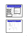
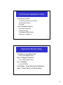
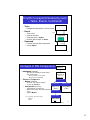
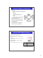
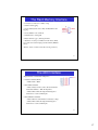
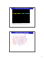
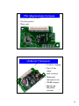
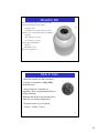
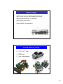
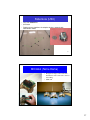
Introduction to Motes
Portions adapted from:
Crossbow, Inc.
Bill Maurer
[email protected]
DSP Labs, Livermore Ca., USA
www.intel-research.net/berkeley/
1
Why Smart Dust ?
• Advances in low power wireless
communication technology and microelectromechanical sensors (MEMS)
transducers
• “Digital Nervous System”
• “Physical Internet”
• “Ubiquitous Computing”
2
1
NEST Technology
• How do you combine sensing,
communication and computation into a
complete architecture ?
• What are the requirements of the
software?
• Networked-Embedded-SystemsTechnology
3
Ad hoc sensing
• Autonomous nodes self
assembling into a network
of sensors
• Sensor information propagated
to central collection point
• Intermediate nodes assist distant
nodes to reach the base station
4
2
Today’s Hardware
• Assembled from off-the-shelf
components
• 8bit MCU
• Low-Power Radio
• Sensors
• I/O
5
Key Software Requirements
• Capable of fine grained
concurrency
• Small physical size
• Efficient resource utilization
• Highly modular
6
3
What is TinyOS ?
• An Open-Source Development Environment
• A Simple Operating System
• A Programming Language and Model
• A Set of Services
7
TinyOS – Development Environment
• Windows and Linux
• Multiple Hardware Platforms
– Not only Crossbow
• Multiple Sensors
– Not only Crossbow
• Debugging Tools
• Reference Applications
8
4
TinyOS – A Simple Operating System
• Scheduler
• Concurrency Intensive
• Limited Resources – SW Components
for Efficient Modularity
9
TinyOS – A Programming Language
and Model
• Separation of construction and
composition:
– programs are built out of components
• Specification of component behavior in
terms of set of interfaces
• Components are statically wired to each
other via their interfaces.
– This increases runtime efficiency
10
5
TinyOS - Services
•
•
•
•
•
•
Radio, MAC, Messaging, Routing
Sensor Interfaces
Power Management
Security
Debug
Time
11
Why TinyOS ?
• Unix Analog (aka 1969)
– A Uniform Programming Language
• C
– A Uniform Abstraction
• E.g, device abstraction
– Open Source
• Many Different Developers
• Many Different Needs
– Many Tools
12
6
Who Controls TinyOS ?
• UC Berkeley Invented
– 1st written by Jason Hill in 2000
– Large portion of development changed to
Intel-Berkeley Research Lab
• Intel-Berkeley Research Lab has largest
role today in core ‘OS’ components
– www.intel-research.net/berkeley/
13
Real-World Deployments
Great Duck Island
http://www.greatduckisland.net/
Center for Embedded Network Sensing
http://www.cens.ucla.edu/
14
7
Introduction to TinyOS and nesC
Programming
•
•
•
•
TinyOS Kernel Design and Implementation
nesC Software Concepts and Basic Syntax
nesC Code Lab
TinyOS Packet Networking and PC Base Station
Lab
15
TinyOS Design Goals
• Support Networked Embedded Systems
– asleep but remain vigilant to stimuli
– bursts of events and operations
• Support Mica Hardware
– power, sensing, computation, communication
• Support Technological Advances
– keep scaling down
– smaller, cheaper, lower power
16
8
TinyOS Design Options
• Can’t Use Existing RTOS’s
– Microkernel Architecture
• VxWorks, QNX, WinCE, PalmOS
– Execution Similar to Desktop Systems
• PDA’s, Cell Phones, Embedded PC’s
– More Than a Order of Magnitude Too
Heavy & Slow
– Energy Hog
17
TinyOS Design Conclusion
• Similar to Building Networking Interfaces
– Data Driven Execution
– Manage Large # of Concurrent Data Flows
– Manage Large # of Outstanding Events
• Add: Managing Application Data Processing
• Conclusion: Need a Multi Threading Engine
– Extremely Efficient
– Extremely Simple
18
9
TinyOS Kernel Design
• TinyOS Kernel: 2 Level Scheduling Structure
– Events
• Small Amount of Processing
• E.g. Timer, ADC Interrupts
• Can Interrupt Longer Running Tasks
– Tasks
•
•
•
•
Not Time Critical
Tasks - Larger Amount of Processing
E.g. Computing an Average on an Array
Run to Completion WRT other Tasks
– Implies Only Need a Single Stack
19
TinyOS Applications Under The
Hood
• Application is created in the nesC Language
– Details of nesC Forthcoming
• nesC Programming Language Supports the
TinyOS Kernel Design (Events and Tasks)
TinyOS Kernel (C)
TinyOS Libs (nesC)
Application (nesC)
nesC
Compiler
Application &
TinyOS (C)
C Compiler
20
Application Executable
10
The TinyOS Kernel Under The Hood
(nesC Compiler C Code Output)
int main(void) {
RealMain$hardwareInit();
TOSH_sched_init();
Hardware and
Kernel
Initialization
bool TOSH_run_next_task(void) {
uint8_t old_full;
void (*func)(void );
if (TOSH_sched_full == TOSH_sched_free) {
return 0;
}
else {
old_full = TOSH_sched_full;
TOSH_sched_full++;
TOSH_sched_full &= TOSH_TASK_BITMASK;
func = TOSH_queue[(int )old_full].tp;
TOSH_queue[(int )old_full].tp = 0;
func();
return 1;
}
}
Application
Initialization
RealMain$StdControl$init();
RealMain$StdControl$start();
RealMain$Interrupt$enable();
while (1) {
TOSH_run_task();
}
Infinite
Loop
1. First Run All Tasks in the Task
Queue (Strictly a FIFO)
}
static inline void TOSH_run_task(void) {
while (TOSH_run_next_task())
;
TOSH_sleep();
TOSH_wait();
}
Task Runs To
Completion (But
May Be Interrupted
By An Event)
2. Then Sleep (In Low Power Mode)
3. And Wait for an Interrupt
21
Overhead of TinyOS Primitive
Operations
Operation
Byte Copy
Signal an Event
Call a Command
Schedule a Task
Context Switch
Cost(cycles)
Time(uSecs)
8
Normalized to Byte Copy
2
1
10
10
46
51
2.5
2.5
11.5
12.75
1.25
1.25
6
6
Hardware Interrupt (hw)
9
Hardware Interrupt (sw) 71
2.25
17.75
1
9
Code and Data Size of the TinyOS
kernel
Processor Init
Scheduler
C runtime
Code Size(bytes)
Data Size(bytes)
172
178
82
30
16
0
432
46
22
11
TinyOS/nesC Application Notes
• Everything is Static
– No Dynamic Memory (no malloc)
– No Function Pointers
– No Heap
• nesC Compiler Analysis
–
–
–
–
Data Race Conditions
Function Inlining
Development Made Easier
Robustness Improved
23
Application Memory Map
• Text/code - Executable Code
– In the 128K Program Flash
• data – Program Constants
– In the 128K Program Flash
• bss - Variables
– In the 4K SRAM
• Free Space - Fixed (No Dynamic Memory)
• stack - Grows Down in the Free Space
24
12
TinyOS Concepts Embodied by nesC
– Tasks, Events, Commands
• Tasks
– Background computation, non-time critical
• Events
–
–
–
–
Time critical
External Interrupts
Originator gives a ‘Signal’
Receiver gets/accepts an ‘Event’
• Command
signal
Component
task
event
command
– Function call to another Component
– Cannot Signal
25
Concepts of SW Components
Main.nc
• Interfaces (xxx.nc)
• Specifies functionality to outside world
• Tell outside world
appxxx.nc
(No code Wiring only)
– what commands can be called
– what events need handling
• Software Components
interfaceA.nc
– Module (xxxM.nc)
• Code file, code implementation
• It codes the Interface
– Configuration (xxxC.nc)
interfaceA.nc
interfaceA.nc
comp1C.nc
comp2M.nc
(code)
• Linking/wiring of components
(wires)
• When top level app, drop C from filename
interfaceB.nc
xxx.nc
• optional Module
TinyOS app Blink – Blinks the Red LED
BlinkM.nc
Blink.nc
interfaceB.nc
comp3M.nc
(code)
26
Ad infinitum...
13
Blink.nc Application - A top level configuration
SW component used to form an executable
tos/system/Main.nc
What the executable does:
1. Main initializes and starts the application.
2.BlinkM initializes ClockC’s rate at 1Hz.
3. ClockC continuously signals BlinkM at a
rate of 1 Hz.
4. BlinkM commands LedsC red led to
toggle each time it receives a signal from
ClockC.
Note: The
StdControl interface
is similar to state
machines (init, start,
stop); used
extensively
throughout TinyOS
apps & libs
tos/interfaces/StdControl.nc
Blink.nc
tos/interfaces/StdControl.nc
BlinkM.nc
Blink.nc
tos/interfaces/Clock.nc
tos/interfaces/Clock.nc
tos/system/ClockC.nc
tos/interfaces/Leds.nc
tos/interfaces/Leds.nc
tos/system/LedsC.nc
27
Mote Hardware
28
14
Family of Motes
29
Mica2 and Mica2Dot
• ATmega128 CPU
1 inch
– Self-programming
• Chipcon CC1000
– FSK
– Manchester
encoding
– Tunable frequency
• Lower power
consumption
30
15
Common Platform Architecture
• Atmega uP
• 32Khz crystal and 4Mhz (7.3728Mhz Mica2)
crystal.
• 10 bit ADC
LEDS
• UART (Mica2/Mica2Dot have 2)
• Radio (RFM or Chipcon 1000)
Atmega uP
SERIAL FLASH
• I2C bus (hardware for mica2/mica2dot)
51 PIN I/O CONNECTOR
• SPI bus
• External serial flash memory (512K byte)
• Connectors for interfacing to sensor and
programming boards
RADIO
• 3 programmable leds (1 for Mica2Dot)
• JTAG port (Mica, Mica2, Mica2Dot)
31
The CC1000 Radio Interface
• Dedicated cpu bus (lines) to configure radio
registers for radio frequency, power,…..
• Dedicated SPI bus for data transfer. CC1000 is
bus master.
• Radio generates one interrupt every 8 bits when
in receive mode.
• Runs usually at 38K or 19K bit rate (default)
Manchester (2x bit)
• More in-depth radio discussion later in session.
Baud Rate Xmt or Rcv Time(*)
19K
~40msec
38K
~20msec
(*) Does not include random delay
32
16
The Flash Memory Interface
• 512 K bytes of flash (non-volatile) storage
• Useful for data logging.
• Used by GSK (Generic Sensor Kit) and TinyDB for data
logging.
• Used by XNP for code download.
• Serial interface to Atmega uP
• TinyOS driver (Logger..) bit bangs interface
• Attached to 2nd uart port on Mica2. Another driver (UCB)
uses synchonous usart for high speed data transfer.(5KB/Sec
driver)
•Beware, device consumes 15 ma when storing to memory
33
The ADC Interface
• Eight channels of 10 bit ADC, multiplexed.
• Dedicated channels (Mica2):
• ADC0 : Radio’s RSSI
• Shared Mica2 Channels
• ADC7 : Battery monitor (can be shared with another
channel but will have ~10K ohm impedance.
• ADC4..ADC7: JTAG. If using JTAG debug these
channels won’t work as ADC inputs.
• Shared Mica2Dot Channels
• ADC1: Shared for both thermistor and battery voltage
• ADC4..ADC7: JTAG. If using JTAG debug these
channels won’t work as ADC inputs
34
17
Mica2 Sensor Interface
Pin
1
2
3
4
5
6
7
Name
GND
VSNR
INT3
INT2
INT1
INT0
BAT_MON
8
9
10
11
12
13
14
15
16
17
18
19
20
21
22
23
24
25
26
LED3
LED2
LED1
RD
WR
ALE
PW7
USART1_CLK
PROG_MOSI
PROG_MISO
SPI_CLK
USART1_RXD
USART1_TXD
I2C_CLK
I2C_DATA
PWMO
PWM1A
AC+
AC-
Description
Ground
Voltage(battery)
GPIO
GPIO
GPIO
GPIO
Battery Monitor
Voltage
Green Led
Yellow Led
Red Led
GPIO
GPIO
GPIO
GPIO
Usart clock
Programmer Pin
Programmer Pin
Radio Clock
Usart1 receive
Usart1 xmit
I2C bus clock
I2C bus data
GPIO
GPIO
GPIO
GPIO
Pin
27
28
29
30
31
32
33
Name
UART_RXDO
UART_TXDO
PWO
PW1
PW2
PW3
PW4
Description
Uart0 Rcv
Uart0 Tx
GPIO/PWM
GPIO/PWM
GPIO/PWM
GPIO/PWM
GPIO/PWM
34
35
36
37
38
39
40
41
42
43
44
45
46
47
48
49
50
51
PW5
PW6
ADC7
ADC6
ADC5
ADC4
ADC3
ADC2
ADC1
ADC0
THERM_PWR
THRU1
THRU2
THRU3
RSTN
PWM1B
VCC
GND
GPIO/PWM
GPIO/PWM
GPIO/ADC CH7, JTAG
GPIO/ADC CH6, JTAG
GPIO/ADC CH5, JTAG
GPIO/ADC CH, JTAG
GPIO/ADC CH3
GPIO/ADC CH2
GPIO/ADC CH1
GPIO/ADC CH0
GPIO
Thru user connect
Thru user connect
Thru user connect
uP reset
GPIO
Voltage (battery)
ground
Blue: OK to use
Yellow: OK to use but has shared functionality
Red: Do no use
See Atmega128 specification for more information regarding signal functionality.
35
Mica2 Sensor Interface
36
18
Mica2Dot Sensor Interface
P IN
TP1
TP2
TP3
TP4
TP5
TP6
TP7
TP8
TP9
T P10
T P11
T P12
T P13
T P14
T P15
T P18
T P19
T P20
T P21
D E S C R IP T IO N
GND
ADC7
ADC6
ADC5
ADC4
VCC
PW 1
PW 0
U A R T _T X D
U A R T _R X D
R ESETN
S P I_ C K
ADC3
ADC2
PW M 1B
GND
IN T 1
IN T 0
T H ER M _PW R
• 6 ADC Channels
• 6 I/O Channels
37
Power Budgets
SYSTEM SPECIFICATIONS
Currents
value
Micro Processor (Atmega128L)
current (full operation)
current sleep
Radio (Chipconn 1000)
current in receive
current xmit
current sleep
Flash Serial Memory (AT45DB041)
write
read
sleep
Sensor Board
current (full operation)
units
6 ma
8 ua
8 ma
12 ma
2 ua
15 ma
4 ma
2 ua
5 ma
Average, full operation, current: ~15 ma
AA Batteries are ~1800ma which mean ~ 120hrs (5 days)
38
19
Batteries
• AA – standard, 1800ma hours. Slow decay. Best price.
•Lithium – 3.6, fast decay, more expensive.
•Beware of low battery voltage (adc, flash programming…..)
•DC Booster may/may not help
•UCB Mica2Dot NiMH 3AH, single cell, with booster and recharge.
39
Crossbow Sensor Boards
Part #
Mote Support
Sensors
MTS101CA
MICA,MICA2
Light (photo resistor)
Temperature (Thermistor)
Prototyping area
MDA300CA
MICA2DOT
Protoyping
MTS300CA
MICA, MICA2
Light, Temperature, Acoustic, Sounder,
2-Axis Accelerometer (ADXL202), and
2-Axis Magnetometer
MTS500CA
Mica2Dot
Prototyping
MDA300CA
Mica2
On board humidity/temp. External sensors.
MTS400/420 Mica2
GPS weatherboard
Not
released:
Weatherboards
Mica2Dot
See MTS/MDA Sensor and Data Acquisition Boards User’s Manual
40
20
MTS101CA
•Light photo resistor-Clairex CL94L
• Thermistor - YSI 44006,
•Both sensor are highly non-linear.
•Good prototyping area.
To use this sensor board add (modify) the
apps/app/makefile for:
SENSORBOARD = basicsb
PW2
PW1
RT1
Thermistor
R2
Photoresistor
ADC5
a b c d e
U 1
1
2 6
1
2
3
4
5
6
7
8
9
10
11
12
2 7
5 1
R3
10K, 5%
T h e r m is t o r ( R T 1 )
gnd_analog
ADC6
R1
10K, 5%
gnd_analog
L ig h t S e n s o r ( R 2 )
41
a b c d e
MDA500CA
• Prototyping board for mica2dots
42
21
MTS300CA/MTS310CA
•
•
•
•
•
•
•
Light (Photo)-Clairex CL94L
Temperature-Panasonic ERT-J1VR103J
Acceleration-ADI ADXL202
– 2 axis
– Resolution: ±2mg
Magnetometer-Honeywell HMC1002
– Resolution: 134µG
Microphone
Tone Detector
Sounder
– 4.5kHz
SENSORBOARD = micasb
43
MTS400/420 – GPS/Weather
• Gps (LeadTek 9546) - optional
• SiRFstartII LP chipset (60ma)
• External active antenna.
• 12 channels
• 15 Meter ( SA off); 7 Meter (WAAS
corrected)
• DC Booster to maintain required
voltage
•Temperature & Humidity (Sensirion
SHT11).
• All digital (14 bits)
• 3.5% RH accuracy, 0.5degC
Temperature accuracy
44
22
MTS400/420 – GPS/Weather
•Barometric Pressure and Temperature
(Intersema MS5534A)
• All digital
• 300 to1100 mbar, 3% accuracy
• -10 to +60 degC, 3% accuracy
• Ambient Light (TAOS TSL2250)
•All digital
•400-1000nm response
•Acceleration-ADI ADXL202
–2 axis
–Resolution: ±2mg
•2 K EEPROM for user configuration info.
45
MDA300
•
•
•
•
•
•
•
8 External Analog Inputs
– External Sensors
– Hi and low level signals
– Block Screw Terminal
8 channel digital I/O
2 relays
On board 12-bit ADC
– 0-2.5V, 0-3V, 0-5V Ranges
Stable 2.5V Reference
3V and 5V power
Designed by UCLA CENS w/
Crossbow and UCB
http://www.cens.ucla.edu/~mhr/daq/46
23
PNI- Magnetometer/Compass
• Resolution: 400 µGauss
• Very low power
• Three axis
47
Ultrasonic Transceiver
• Used for ranging
• Up to 2.5m
range
• 6cm accuracy
• Dedicated
microprocessor
• 25kHz element
• Mica2 and
Mica2Dot
48
versions
24
Mica2Dot WB
• UCB environmentally packaged weatherboards for GDI
•Temperature & Humidity (Sensirion SHT11).
• All digital (14 bits)
• 3.5% RH accuracy, 0.5degC Temperature accuracy
•Barometric Pressure and Temperature (Intersema MS5534A)
• All digital
• 300 to1100 mbar, 3% accuracy
• -10 to +60 degC, 3% accuracy
•Ambient Light (TAOS TSL2250)
•All digital
•400-1000nm response
• Photosensitive Light Sensor..
49
Mote In Tires
• Real time control of vehicle dynamics.
•3 bridge accelerometers (500g-1000g)
mounted in tire.
• Sensor board has 3 channels of
amplifiers, filters, programmable D/As for
bridge balancing.
•Monitor and analyzed acceleration forces
when tire is in contact with ground.
• Transmit results every revolution.
• 3 motes, 1 master, 2 slaves.
50
25
Micro Radar
•Darpa project: Detect intruders with micro-powered
radar detectors and relay data through mote network.
•Drop detectors from UAV (ex: Predator)
•Ghz Doppler radar detector.
• Done with LLL and Advantaca
51
COTS-BOTS (UCB)
• 5” x 2.5” x 3” size
• <$250 total
• 2-axis accelerometer
52
26
Robomote (USC)
• Less than 0.000047m3
• $150 each
• Platform to test algorithms for adaptive wireless networks with
autonomous robots
53
MICAbot (Notre Dame)
•
•
Designed for large-scale research in
distributed robotics and ad-hoc wireless
networking.
$300 each
54
27
Ratiometric Adcs & Sensors
• Atmega128 is 10 bit (1024) ratio metric ADC
• If sensor is ratio metric then don’t have to
measure battery voltage. (Sensor’s FS changes
with battery voltage).
•Ratio metric sensors may not work over full range
of battery voltage.
•ADC full scale is proportional to battery voltage.
• Must measure battery voltage to get accurate
sensor readings:
ADC Output vs Battery
Voltage for 1.5V input
700
680
660
640
620
600
580
560
540
520
500
2
2.5
3
3.5
Battery Volts = RefVolt*ADC_FS/data
•Mica2 and Mica2Dot have on-board voltage
references to calibrate the ADC full scale.
/contrib/xbow/apps/XSensorMica2
55
Enclosures for Environmental
Monitoring
56
28
Mica2Dot Enclosures
Weather Sensors
On/Off
O-Ring
Battery Interface Board
Battery
57
Sensor Power Management
• Simple Strategy for Low Power Sensors:
PW2
• Use Atmega output pins to source sensor power.
RT1
Thermistor
• Will source ~5-10ma of current per pin.
R3
10K, 5%
ADC5
• Analog Switch Strategy
gnd_analog
• Use hardware I2C (mica2) or software I2C
(mica2dot) (in Sourceforge)
VCC
• Switch connects sensor power to VCC.
I2C_BUS_1_DATA
I2C_BUS_1_CLK
• Create +5 V or more
I2C_BUS_1_DATA
I2C_BUS_1_CLK
VCC
S8
S7
S6
S5
S4
S3
S2
S1
ADG715BRU
19
D8 17
D7 15
D6 13
D5 12
D4 10
D3 8
D2 6
D1
3
1 SDA
SCLK
23
24 RST
22 A0
A1
5V_DC-DC_Shutdown
3.3V_DC-DC_Shutdown
Accel_Power
EEPROM_Power
Humidity_Power
Pressure_Power
Light_Power
R11 R9
1M 1M
R10 R13 R12
1M 1M 1M
VSS
GND
• DC-DC Booster Strategy
U7
21
4
Accel_Out
20
18
16
14
11
9
7
5
2
R19 R17
1M 1M
• ADG714 switch has 2.5 ohm on resistance
• Create battery independent, constant supply
voltage.
Power
Switches
• Turn on booster from analog switch or Atmega
• Boosters are ~80%-90% efficient. Need good layout
and decoupling. Not ratiometric
58
29
Mote Programming and Base Station
Boards
Overview:
• MIB500 Parallel Port Programmer
• MIB510 Serial Port Programmer
• eMote
• USB
59
MIB500
•Programs mote through the PC’s parallel port
•Supports Mica, Mica2, Mica2Dot
•Voltage monitor to protect from low battery voltage.
Low battery voltage can cause fuse errors.
•Serial port for base station operation
•Parallel port can cause flash corruption on some
computers due to uisp parallel port drivers. THESE
MAY BE IRRECOVERABLE
• Crossbow application note at www.xbow.com to
help fix uisp problems.
• JTAG connector: AVRStudio and JTAG pod allows
viewing and setting all fuses.
60
30
MIB510
• Q3 release
•Programming through the serial port.
On board ISP uP is 3x faster than
parallel port.
•Shares serial port with mote for base
station operation.
•Voltage monitor to protect from low
battery voltage
• Suports Mica (Atmega128 uP only),
Mica2, Mica2Dot
• JTAG port powered directly.
61
USB
• Q4 release
•USB interface for programming and base station
operation .
•Power supplied thru USB.
62
31
eMote
Ethernet connection as serial forwarder.
•Programming through ethernet.
ISP uP
Serial
• Remote powered ethernet sensor.
• Remote code debugging through ethernet.
Ideal for mote network debug.
Ethernet
• Remote base station operation through
ethernet.
Serial
MOTE
SENSOR BOARD
• Similar configuration (eprb) used
extensively at UCB for mote development.
63
32