1
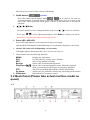
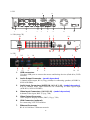
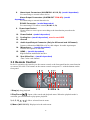
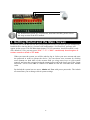
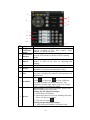
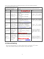
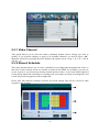
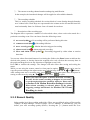
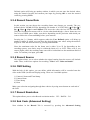
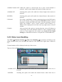
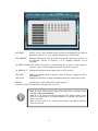
7 Lock ( ): you will logout the system if you press this button. 8 Numerical Button: Using these buttons, you can choose to output video on your monitor either as a full-screen view of each of the cameras individually (Channels 1 through 9). 9 Rewind (◄◄): Rewind video during playback. 10 Fast Forward (►►): Fast forward video during playback 12 ENTER: This button is used as the “enter” key in most circumstances. And on live view press this button to bring up tool bar. 13 Spot View ( ): Press to enable auto sequencing. 14 Quad ( ): Press this button to switch display modes. There are 4-CH mode, 6-CH mode, 8-CH mode, 9-CH mode. You can use it according to your demand. Can be used as FN icon too, Assistant function: In motion detection area and record mode, press it to enter or quit paste state. And in playback search, press it can be set the start time or end time to playback. 15 REC (●): Start or Stop manual recording. 3.4 Hardware Installation It is recommended that the installations described below are carried out by qualified personnel. 3.4.1 Basic Connections Cameras Connect each of the cameras’ outputs to the video input socket in the rear panel of the DVR using appropriate cables. The video input interface is a standard BNC connector, 1Vp-p, 75 Ω. Please keep the video signal cable away from strong electromagnetic and electric interference. Audio Connection The audio input interface is a standard RCA socket, 2Vp-p, 600 Ω. Please keep the audio signal cable away from strong electromagnetic and electric interference. Monitor Connect the main output connector to a monitor or a TV screen. Use the BNC-to-RCA connector to work with the Audio/Video RCA cable. Power Please use the 12V DC adapter supplied for connecting your DVR device with the power source. Alarm Input/Output Connect Alarm In 1-4 to N.O. (Normally Open) or N.C. (Normally Closed) alarm connectors and one Ground connection. Connect Alarm Out to the corresponding connections and Ground accordingly. 14