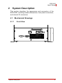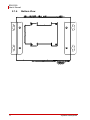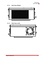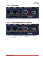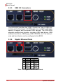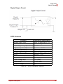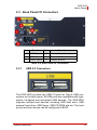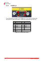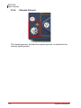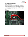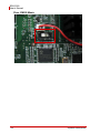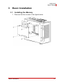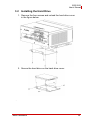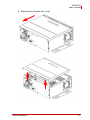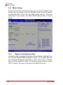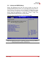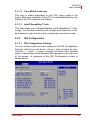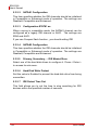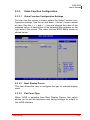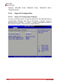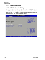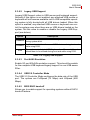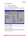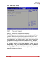
1
EOS-2000 4-CH Compact Vision System User’s Manual Manual Revision: 2.02 Revision Date: December 9, 2010 Part Number: 50-1Z065-1000 Advance Technologies; Automate the World. EOS-2000 User’s Manual ii EOS-2000 User’s Manual Table of Contents Table of Contents................................................................... iii List of Tables......................................................................... vii 1 Introduction ........................................................................ 1 1.1 Product Overview ................................................................ 1 1.1.1 Key Features ................................................................... 1 1.2 Specifications....................................................................... 2 1.3 Unpacking Checklist ............................................................ 3 2 System Description............................................................ 5 2.1 Mechanical Drawings........................................................... 5 2.1.1 Front View........................................................................ 5 2.1.2 Rear View ........................................................................ 6 2.1.3 Top View ......................................................................... 7 2.1.4 Bottom View..................................................................... 8 2.1.5 Side View (Right) ............................................................. 9 2.1.6 Side View (Left) ............................................................... 9 2.2 Front Panel I/O Connectors ............................................... 10 2.2.1 Reset Button .................................................................. 11 2.2.2 Keyboard and Mouse PS2 connectors .......................... 11 2.2.3 USB 2.0 Connectors ...................................................... 12 2.2.4 Gigabit Ethernet Ports ................................................... 12 2.2.5 VGA Connector.............................................................. 13 2.2.6 COM1 Port..................................................................... 13 2.2.7 Digital I/O (PCM-7230+) ................................................ 14 2.2.8 Analog Video Input Port (RTV24) .................................. 16 2.2.9 CompactFlash Socket.................................................... 20 2.3 Back Panel I/O Connectors .............................................. 21 2.3.1 USB 2.0 Connectors ...................................................... 21 2.3.2 COM2 Port..................................................................... 22 Table of Contents iii EOS-2000 User’s Manual 2.3.3 Power Switch ................................................................. 23 2.3.4 AC Power Input Connector ............................................ 23 2.3.5 DC Power Input Connector............................................ 23 2.3.6 Chassis Ground ............................................................ 24 2.4 Internal I/O Connectors...................................................... 25 3 Basic Installation .............................................................. 27 3.1 Installing the Memory......................................................... 27 3.2 Installing the Hard Drive..................................................... 29 3.3 Installing the Fan................................................................ 33 3.4 Installing the filter ............................................................... 35 3.5 Installing the Wallmount Brackets...................................... 36 4 Software Support .............................................................. 37 4.1 Operation System Support................................................. 37 4.1.1 Windows XP .................................................................. 37 4.1.2 Windows XP Embedded ................................................ 37 4.2 Driver Installation ............................................................... 39 4.2.1 Installing the Chipset Driver........................................... 39 4.2.2 Installing the Graphics Driver......................................... 40 4.2.3 Installing the PCMe-RTV24 Driver................................. 40 4.2.4 Installing the Audio Driver.............................................. 52 4.2.5 Installing the PCM-7230+ Driver.................................... 52 4.3 Hardware Monitor Application............................................ 56 4.3.1 Programming Guide....................................................... 56 4.4 ViewCreatorPro Utility........................................................ 58 4.4.1 Overview........................................................................ 58 4.4.2 Component Description ................................................. 59 4.4.3 Operation Theory........................................................... 60 4.5 Function Library ................................................................. 72 4.5.1 List of Functions............................................................. 72 4.5.2 C/C++ Programming Library .......................................... 73 iv Table of Contents EOS-2000 User’s Manual 4.5.3 System Functions .......................................................... 74 4.5.4 Configuration Functions................................................. 80 4.5.5 Image Grabbing ............................................................. 90 4.5.6 GPIO & EEPROM Functions ......................................... 95 4.5.7 Callback & Thread Functions....................................... 101 4.5.8 Watchdog Timer .......................................................... 107 4.5.9 Software Trigger .......................................................... 109 4.5.10Frame Buffer................................................................ 112 4.5.11Angel RTV LabVIEW Function Library ........................ 117 4.6 Programming Guide......................................................... 124 4.6.1 DirectShow Programming Guide ................................. 124 4.6.2 LabVIEW Programming Guide .................................... 139 5 BIOS Setup...................................................................... 145 5.1 Starting the BIOS............................................................. 145 5.1.1 Setup Menu ................................................................. 145 5.1.2 Navigation.................................................................... 146 5.2 Main Setup....................................................................... 148 5.2.1 System Time/System Date .......................................... 148 5.3 Advanced BIOS Setup..................................................... 149 5.3.1 CPU Configuration....................................................... 150 5.3.2 IDE Configuration ........................................................ 151 5.3.3 Video Function Configuration ...................................... 153 5.3.4 Super IO Configuration ................................................ 154 5.3.5 Hardware Health Configuration ................................... 157 5.3.6 USB Configuration ....................................................... 158 5.3.7 ACPI Configuration ...................................................... 160 5.3.8 AHCI Configuration...................................................... 161 5.3.9 Remote Access Configuration ..................................... 162 5.4 PCIPnP Setup.................................................................. 163 5.4.1 PCI PnP Configuration................................................. 163 5.5 Boot Setup ....................................................................... 165 Table of Contents v EOS-2000 User’s Manual 5.5.1 Boot Settings ............................................................... 166 5.6 Security Setup.................................................................. 169 5.6.1 Password Support ....................................................... 169 5.7 Chipset Configuration ...................................................... 171 5.7.1 Chipset Settings........................................................... 171 5.7.2 LAN 82574L PXE ROM Init ......................................... 171 5.7.3 South Bridge Chipset Configuration ............................ 172 Important Safety Instructions............................................. 175 vi Table of Contents EOS-2000 User’s Manual List of Tables Table Table Table Table Table Table Table Table Table Table Table Table Table Table Table Table Table Table Table Table Table 1-1: 1-2: 2-1: 2-2: 2-3: 2-4: 2-5: 2-6: 2-7: 2-8: 2-9: 2-10: 4-1: 4-2: 4-3: 5-1: 5-2: 5-3: 5-4: 5-5: 5-6: List of Tables EOS-2000 Specifications................................................. 2 Unpacking Checklist ........................................................ 3 Gigabit Ethernet Port Pinout .......................................... 12 COM1 Port Pinout.......................................................... 13 Digital I/O Pinout............................................................ 15 Image Acquisition Speed ............................................... 16 Video Ports 0 - 3 Pinout................................................. 17 GPIO Pinout .................................................................. 18 GPIO Hardware Features .............................................. 19 Back Panel I/O Connectors ........................................... 21 COM2 Port Pinout.......................................................... 22 Power Switch ................................................................. 23 List of Functions............................................................. 72 C/C++ Data Types ......................................................... 73 Pixel Data .................................................................... 112 BIOS Navigation .......................................................... 146 Serial Port1 Address.................................................... 155 Serial Port2 Address.................................................... 155 COM Port RS485 Support ........................................... 156 Legacy USB Support ................................................... 159 Restore on AC Power Loss ......................................... 161 vii EOS-2000 User’s Manual viii List of Tables EOS-2000 User’s Manual Preface Copyright 2010 ADLINK TECHNOLOGY INC. This document contains proprietary information protected by copyright. All rights are reserved. No part of this manual may be reproduced by any mechanical, electronic, or other means in any form without prior written permission of the manufacturer. Disclaimer The information in this document is subject to change without prior notice in order to improve reliability, design, and function and does not represent a commitment on the part of the manufacturer. In no event will the manufacturer be liable for direct, indirect, special, incidental, or consequential damages arising out of the use or inability to use the product or documentation, even if advised of the possibility of such damages. Trademarks Borland® C/C++ and Delphi® are registered trademarks of the Borland Software Corporation. Intel® is a registered trademark of Intel Corporation. LabVIEW™ is a trademark of National Instruments Corporation. Linux® and the Linux® Logo are registered trademarks of Linus Torvalds. MATLAB® and the MATLAB Logo are registered trademarks of The MathWorks, Inc. Microsoft®, MS-DOS®, Windows® 95, Windows® 98, Windows NT®, Windows® 2000, Windows® 2003 Server®, Windows® XP, Windows Vista®, ActiveX®, Visual Studio®, Visual Basic®, Visual C#®, and Visual C++® are registered trademarks of Microsoft Corporation. PCI™, CompactPCI®, and PCI Express®, are registered trademarks of the Peripheral Component Interconnect Special Interest Group (PCI-SIG). PXI™ is a trademark of the PXI systems Alliance. VEE™ is a trademark of Agilent. Product names mentioned herein are used for identification purposes only and may be trademarks and/or registered trademarks of their respective companies. ix EOS-2000 User’s Manual Getting Service Contact us should you require any service or assistance. ADLINK Technology Inc. Address: 9F, No.166 Jian Yi Road, Chungho City, Taipei County 235, Taiwan קᗼխࡉؑ৬ԫሁ 166 ᇆ 9 ᑔ Tel: +886-2-8226-5877 Fax: +886-2-8226-5717 Email: [email protected] Ampro ADLINK Technology Inc. Address: 5215 Hellyer Avenue, #110, San Jose, CA 95138, USA Tel: +1-408-360-0200 Toll Free: +1-800-966-5200 (USA only) Fax: +1-408-360-0222 Email: [email protected] ADLINK Technology Beijing Address: ࣫ҀᏖ⍋⎔ऎϞഄϰ䏃 1 োⲜ߯ࡼॺ E ᑻ 801 ᅸ (100085) Rm. 801, Power Creative E, No. 1, B/D Shang Di East Rd., Beijing 100085, China Tel: +86-10-5885-8666 Fax: +86-10-5885-8625 Email: [email protected] ADLINK Technology Shanghai Address: Ϟ⍋Ꮦⓩ⊇⋒催⾥ᡔᓔথऎ䩺∳䏃 333 ো 39 ᐶ 4 ሖ (200233) Tel: +86-21-6495-5210 Fax: +86-21-5450-0414 Email: [email protected] ADLINK Technology Shenzhen Address: ⏅ഇᏖफቅऎ⾥ᡔುफऎ催ᮄफϗ䘧᭄ᄫᡔᴃು A1 ᷟ 2 ὐ C ऎ (518057) 2F, C Block, Bld. A1, Cyber-Tech Zone, Gao Xin Ave. Sec 7, High-Tech Industrial Park S., Shenzhen, 518054 China Tel: +86-755-2643-4858 Fax: +86-755-2664-6353 Email: [email protected] x EOS-2000 User’s Manual ADLINK Technology (Europe) GmbH Address: Nord Carree 3, 40477 Duesseldorf, Germany Tel: +49-211-495-5552 Fax: +49-211-495-5557 Email: [email protected] ADLINK Technology, Inc. (French Liaison Office) Address: 15 rue Emile Baudot, 91300 Massy CEDEX, France Tel: +33 (0) 1 60 12 35 66 Fax: +33 (0) 1 60 12 35 66 Email: [email protected] ADLINK Technology Japan Corporation Address: 151-0072 ᧲੩ㇺᷦ⼱ᐈ䊱⼱㩷 1-1-2 ᦺᣣ↢ᐈ䊱⼱䊎䊦 8F Asahiseimei Hatagaya Bldg. 8F 1-1-2 Hatagaya, Shibuya-ku, Tokyo 151-0072, Japan Tel: +81-3-4455-3722 Fax: +81-3-5333-6040 Email: [email protected] ADLINK Technology, Inc. (Korean Liaison Office) Address: 昢殾柢 昢爎割 昢爎壟 1506-25 穢壊 B/D 2 猻 2F, Hando B/D, 1506-25, Seocho-Dong, Seocho-Gu, Seoul 137-070, Korea Tel: +82-2-2057-0565 Fax: +82-2-2057-0563 Email: [email protected] ADLINK Technology Singapore Pte. Ltd. Address: 84 Genting Lane #07-02A, Cityneon Design Centre, Singapore 349584 Tel: +65-6844-2261 Fax: +65-6844-2263 Email: [email protected] ADLINK Technology Singapore Pte. Ltd. (Indian Liaison Office) Address: No. 1357, "Anupama", Sri Aurobindo Marg, 9th Cross, JP Nagar Phase I, Bangalore - 560078, India Tel: +91-80-65605817 Fax: +91-80-22443548 Email: [email protected] xi EOS-2000 User’s Manual This page intentionally left blank. xii EOS-2000 User’s Manual 1 Introduction 1.1 Product Overview ADLINK’s EOS-2000 is a rugged and embedded vision system that features an Intel® Multicore processor and four channel NTSC/PAL image acquisition. This system is ideal for high computing power and multi-camera imaging applications such as alignment, assembly inspection, and gauge. By selecting long-life embedded components and incorporating system monitoring components to watch CPU temperature, fan speed, and system responsiveness, the EOS-2000 provides a very robust and reliable platform for mission critical applications. 1.1.1 Key Features Compact and rugged system design Embedded Intel® Core 2 Duo CPU Multi-camera support: up to four NTSC/PAL cameras Rich I/O support: RS-232/485, USB, and isolated digital I/ Os Dual storage support: HDD and CompactFlash cards Hardware Monitoring: temperature, voltage, and watchdog Introduction 1 EOS-2000 User’s Manual 1.2 Specifications EOS-2000 CPU Intel® Core 2 Duo P8400, 2.26GHz System Memory Up to 4 GB DDR3 Camera Interface 4 Ch NTSC/PAL Chipset Intel® GM45 / ICH9 Chipset VGA Analog CRT support up to 1600 x 1200 USB Four USB ports, USB 2.0 compliant Audio AC97, Mic In/Speaker Out COM Ports COM1/COM2: RS-232/RS-422/RS-485(BIOS Setting) Digital I/O 16-CH Isolated Digital Input, and Output, 5.0 KV isolation protection Keyboard/Mouse Combed PS/2 type mini-DIN connectors Power Supply DC: 10~30 VDC, AT mode AC: 100~240 VAC, AT mode Operating Temp. 0˚C to 55˚C Humidity 0% to 90% Dimensions 200(W) x 165(D) x 85(H) mm Power Consumption With 2 GB DDRAM, and 2GB CompactFlash, 50 W Storage One CompactFlash Type I; One 2.5’ SATA HDD(Option) Random Vibration Operating: 5 to 100Hz, 0.00142 g2/Hz; 100 to 500Hz, -6 dB/Octave, 0.5 Grms, 3 axes, 30 minutes/axis Safety Compliance CE/FCC, RoHS Table 1-1: EOS-2000 Specifications 2 Introduction EOS-2000 User’s Manual Warning: Always disconnect the power cord from your chassis whenever you are working on it. Do not connect the power cord while the power switch is on. A sudden rush of power can damage sensitive electronic components. Only authorized and experienced electronics personnel should open the chassis. Always ground yourself to remove any static electric charge before touching EOS-1000. Modern electronic devices are very sensitive to static electric charges. Use a grounding wrist strap at all times. Place all electronic components on a static-dissipative surface or in a staticshielded bag. 1.3 Unpacking Checklist Before unpacking, check the shipping carton for any damage. If the shipping carton and/or contents are damaged, inform ADLINK immediately. Retain the shipping carton and packing materials for inspection. Obtain authorization from your dealer before returning any product to ADLINK, check if the following items are included in the package. Product Included Items EOS-2000 All-in-one support CD-ROM (software & manuals) Wall mounting kit: Wall mounting brackets (x2) M4 screws, 0.7 mm pitch, 5 mm length (x4) Power cord (L=1.8 M, country of use to be specified while ordering, for AC units only) PS/2 Y cable (x1) DSUB to BNC cable (x1) Table 1-2: Unpacking Checklist Note: Introduction The packaging for the OEM version with non-standard configuration, functionality, or package may vary according to different configuration requests. 3 EOS-2000 User’s Manual This page intentionally left blank. 4 Introduction EOS-2000 User’s Manual 2 System Description This section describes the appearance and connectors of the EOS-2000, including chassis dimensions, front panel connectors, and internal IO connectors. 2.1 Mechanical Drawings System Description 8 7, 5 Front View 82 2.1.1 5 EOS-2000 User’s Manual 2.1.2 Rear View AC Power: DC Power: 6 System Description EOS-2000 User’s Manual 19 ,8 3 2 ,3 10 10 80 17 1 Top View 125 2.1.3 System Description 7 EOS-2000 User’s Manual 2.1.4 8 Bottom View System Description EOS-2000 User’s Manual 2.1.5 Side View (Right) 2.1.6 Side View (Left) System Description 9 EOS-2000 User’s Manual 2.2 Front Panel I/O Connectors Symbol A Function Reset button B PS2 keyboard & mouse C USB2.0 ports D Dual Gigabit Ethernet ports E VGA connector F COM port G Digital I/O connector H 4 channel Power over Ethernet Connectors I Compact Flash socket Figure 2-1: Front Panel I/O Connectors 10 System Description EOS-2000 User’s Manual 2.2.1 Reset Button The reset button is used to perform a hard reset on the EOS-2000. A pin-like object can be used to push the reset button. 2.2.2 Keyboard and Mouse PS2 connectors The EOS-2000 provides connectors for connecting PS2 keyboard and mouse. The green connector is for PS/2 mouse and the purple one is for PS/2 key-board. System Description 11 EOS-2000 User’s Manual 2.2.3 USB 2.0 Connectors The EOS-2000 provides two USB 2.0 ports via Type A USB connectors on the front panel. All USB ports are compatible with highspeed, full-speed and low-speed USB devices. The EOS-2000 supports multiple boot devices, including USB flash drives, USB external hard drive, USB floppy, USB CD-ROM, etc. The boot priority and boot device can be configured in the BIOS. 2.2.4 Gigabit Ethernet Ports 1 8 Pin Signal Pin Signal 1 MDI0+ 5 MDI2- 2 MDI0- 6 MDI1- 3 MDI1+ 7 MDI3+ 4 MDI2+ 8 MDI3- Table 2-1: Gigabit Ethernet Port Pinout 12 System Description EOS-2000 User’s Manual 2.2.5 VGA Connector The D-sub 15-pin VGA connector is used to connect the EOS2000 to a monitor. The EOS-2000 supports only analog (VGA) monitors. 2.2.6 COM1 Port 1 5 6 9 The EOS-2000 provides one COM port in the form of D-Sub 9P connectors on the front panel. The COM1 port supports RS-232 only. Pin Signal Name Pin Signal Name RS-232 1 DCD# 6 DSR# 2 RXD# 7 RTS# 3 TXD# 8 CTS# 4 DTR# 9 RI# 5 GND Table 2-2: COM1 Port Pinout System Description 13 EOS-2000 User’s Manual 2.2.7 Digital I/O (PCM-7230+) The EOS-2000 features a 16 channels isolated digital I/O card (PCM-7230+). The onboard digital I/O card supports the following features: 16-CH Isolated DI Logic high: 3 – 24 V Logic low: 0 – 1 V Input resistance: 1.2 k @ 0.5 W Isolation voltage: 1000 Vrms Interrupt source: DI channel 0 and 1 16-CH Isolated DO Output type: Darlington transistors Output voltage: open collector 5 V(min.), up to 35 VDC(max.) Sink current: 500 mA max @ 100% duty, for one of the eight transistor devices ON 370 mA @ duty 10% for all transistors devices ON 140 mA @ duty 50% for all transistors devices ON Note: the pulse width is 25 ms for one duty cycle 14 Isolated voltage: 1000 Vrms @ 10 seconds System Description EOS-2000 User’s Manual 19 1 37 20 Pin Signal Name Pin Signal Name Pin Signal Name 1 IDI_0 14 IDO_6 27 IDI_15 2 IDI_2 15 IDO_8 28 EOGND 3 IDI_4 16 IDO_10 29 EOGND 4 IDI_6 1 30 IDO_1 5 IDI_8 18 IDO_14 31 IDO_3 6 IDI_10 19 VDD 32 IDO_5 7 IDI_12 20 IDI_1 33 IDO_7 8 IDI_14 21 IDI_3 34 IDO_9 9 EICOM IDO_12 22 IDI_5 35 IDO_11 10 EOGND 23 IDI_7 36 IDO_13 37 IDO_15 11 IDO_0 24 IDI_9 12 IDO_2 25 IDI_11 13 IDO_4 26 IDI_13 Table 2-3: Digital I/O Pinout Legend: IDI_n: Isolated digital input channel #n. IDO_n: Isolated digital output channel #n. EOCOM: Common Ground or Common power of isolated input channels. EOGND: Ground return path of isolated output channels. VDD: Power input signal for fly-wheel diode of DO channels. Note: The VDD must be supplied by an external power supply of 5 to 35 VDC System Description 15 EOS-2000 User’s Manual 2.2.8 Analog Video Input Port (RTV24) This port ccepts standard composite color (PAL, NTSC) or monochrome video formats (CCIR, EIA). The square-pixel and broadcast resolutions are programmable (640 x 480 or 768 x 576). Before images are transferred into the PC’s memory, the resolution can be scaled down using selectable ratios. Arbitrary cropping to regions of interest is supported. The RTV series generates bitmaps in all popular color formats such as RGB. Image Acquisition Speed NTSC 1 Camera 2 Cameras 3 Cameras 4 Cameras Fields 60 120 180 240 Frames 30 60 90 120 PAL 1 Camera 2 Cameras 3 Cameras 4 Cameras Fields 50 100 150 200 Frames 25 50 75 100 Table 2-4: Image Acquisition Speed Color Image The color video format is compatible with the following composite video input formats: NTSC-M, NTSC-Japan, PCL-B, PAL-D, PALG, PAL-H, PAL-I, PAM-M, PAL-N, and SECAM Monochrome Image The monochrome video acquisition is compatible with CCIR and EIA (RS-170) Optional Scaling Optional scaling of acquired image or portions of an image. 16 Acquisition of a programmable area of interest Scaling of the image (down to 1:16) Adjustment of hue (for NTSC signals), contrast (0 to 200%), brightness and saturation (0 to 200% for U and V signals) Automatic chrominance gain control System Description EOS-2000 User’s Manual GPIO The RTV24 is also ideal for automation applications by providing four of each isolated digital inputs and outputs. Power Output Provides DC +12V, max. 1A output (GPIO connector pin 25) Note: This power is not isolated with the system, but its ground is the reference GND pin. Video Prots 0-3 Pin Signal Name Pin Signal Name Pin Signal Name 1 Port 0 video in 10 GND 19 Port 3 video in -- 11 GND 20 -- 12 GND 21 -- Port 1 video in 13 GND 22 GND 2 3 4 -- 5 -- 14 GND 23 GND 6 -- 15 GND 24 GND 7 GND 25 GND 8 Port 2 video in 16 -- 17 GND 26 GND 9 -- 18 GND Table 2-5: Video Ports 0 - 3 Pinout System Description 17 EOS-2000 User’s Manual GPIO Pin Signal Name Pin Signal Name Pin Signal Name 1 In0 10 Out0 19 -- 2 3 ComI0 11 In1 12 ComO0 20 -- Out1 21 -- 4 ComI1 5 In2 13 ComO1 22 -- 14 Out2 23 -- 6 7 ComI2 15 ComO2 24 -- In3 16 Out3 25 12V out, 8 ComI3 17 ComO3 26 GND 9 Frame GND 18 Frame GND Table 2-6: GPIO Pinout Digital Input Circuit 18 System Description EOS-2000 User’s Manual Digital Output Circuit GPIO Features Function Electronic Specification Isolated Digital Input Photo Coupled Input x 4 ch Status Normal is High Input voltage range (ComI to In) 0 to 25 V High Level (active off) ComI to In < 0.5 V Low Level (active on) ComI to In > 2.2 V Isolated Digital Output Photo Coupled Output x 4 ch Status Normal is Close Load voltage range 3 to 24V Output sink current 80 mA (Max) Output voltage drop 1.0 V (Max) Leak current 0.1 mA (Max) Reverse voltage -6 V Table 2-7: GPIO Hardware Features System Description 19 EOS-2000 User’s Manual 2.2.9 CompactFlash Socket The CompactFlash socket of EOS supports both DMA and PIO mode. 20 System Description EOS-2000 User’s Manual 2.3 Back Panel I/O Connectors Item Function Item J USB2.0 ports M Function Mic in and speaker out K COM port N Power in (AC model shown) L Power switch O Chassis ground Table 2-8: Back Panel I/O Connectors 2.3.1 USB 2.0 Connectors The EOS-2000 provides two USB 2.0 ports as Type A USB connectors on the back panel. All USB ports are compatible with highspeed, full-speed and low-speed USB devices. The EOS-2000 supports multiple boot devices, including USB flash drive, USB external hard drive, USB floppy, USB CD-ROM and etc. The boot priority and boot device can be configured in BIOS. System Description 21 EOS-2000 User’s Manual 2.3.2 COM2 Port 1 5 6 9 The EOS-2000 provides one COM port in the form of D-Sub 9P connectors on the front panel. COM2 port supports RS-232 only. Pin Signal Name Pin Signal Name RS-232 1 DCD# 6 DSR# 2 RXD# 7 RTS# 3 TXD# 8 CTS# 4 DTR# 9 RI# 5 GND Table 2-9: COM2 Port Pinout 22 System Description EOS-2000 User’s Manual 2.3.3 Power Switch O Off I On Table 2-10: Power Switch 2.3.4 AC Power Input Connector The AC power input connector is a standard 100-240 VAC 50/60 Hz three-pin connector. 2.3.5 DC Power Input Connector The DC power input connector of the EOS-2000 controller consists of two pins, V+ and V- from left to right respectively. V+ and V- pins are for DC power input. The DC power input of EOS-2000 allows a voltage input from 10 VDC to 30 VDC. System Description 23 EOS-2000 User’s Manual 2.3.6 Chassis Ground The chassis ground, isolated from power ground, is shorted to the internal signal ground. 24 System Description EOS-2000 User’s Manual 2.4 Internal I/O Connectors 2.4.1Clear CMOS Switch If abnormal condition that causes the EOS-2000 controller fail to boot are experienced, you can try to clear the BIOS content stored in the CMOS and restore to the default setting. To clear the CMOS, just press the button and hold for 1-2 seconds before release it. The CMOS will then be restored to its factory default setting. Normal Mode: System Description 25 EOS-2000 User’s Manual Clear CMOS Mode: 26 System Description EOS-2000 User’s Manual 3 Basic Installation 3.1 Installing the Memory 1. Remove the four screws in the figure below. Basic Installation 27 EOS-2000 User’s Manual 2. Insert the memory module into the DDR3 SO-DIMM at a 45 degree angle. Then put down until the memory module snaps into place. 28 Basic Installation EOS-2000 User’s Manual 3.2 Installing the Hard Drive 1. Remove the four screws and unload the hard drive cover in the figure below. 2. Secure the hard drive on the hard drive cover. . Basic Installation 29 EOS-2000 User’s Manual 3. Insert the SATA power cable and data cable on the hard drive. 4. Secure the hard drive cover back. 30 Basic Installation EOS-2000 User’s Manual 5. Remove the chassis top cover. Basic Installation 31 EOS-2000 User’s Manual 6. Insert the SATA data cable. 32 Basic Installation EOS-2000 User’s Manual 3.3 Installing the Fan 1. Remove the box cover and secure the fan on the side of box. Basic Installation 33 EOS-2000 User’s Manual 2. Insert the fan power cable on the power connector on the motherboard (RB-850). 34 Basic Installation EOS-2000 User’s Manual 3.4 Installing the filter 1. Remove the box cover and stick the mesh on the filter, then secure the filter on the side of box. Basic Installation 35 EOS-2000 User’s Manual 3.5 Installing the Wallmount Brackets 1. Secure the wallmount brackets on the bottom of box. 36 Basic Installation EOS-2000 User’s Manual 4 Software Support Selecting an operating system (OS) suitable for the application requirements is vital for system developers. The EOS-2000 is compatible with several operating systems for maximum flexibility. 4.1 Operation System Support 4.1.1 Windows XP Windows XP supports the EOS-2000 chipset drivers, allowing simple installation of this OS. ADLINK also provides pre-installation services for Windows XP on the EOS-2000 (requires the Windows XP license to be pre-purchased from ADLINK). 4.1.2 Windows XP Embedded Windows XP is a multitasking OS known for its stability. As a result of its overwhelming popularity, human-machine interfaces, and plentiful development tools, developing applications in Windows XP is comparatively simple. Microsoft carried over the advantages of Windows XP when releasing Embedded XP. The concept behind the design of Embedded XP is simply a modularized Windows XP. System developers only select the needed Windows XP components and functions and then organize them together to construct an XP Embedded OS. By using this architectural modularization, system integrators can readily reduce the storage space requirements of XP Embedded. The only factor determining storage space requirements is the number of function modules needed. Because XP Embedded is completely compatible with Windows XP, developers can compile controller software in the Windows XP environment, and then transfer the code to Embedded XP for immediate use. System developers do not need to learn any new tools to use XP Embedded. Their experience on Windows XP can be directly transferred to XP Embedded, thus lowering software development costs. Another advantage is that the cost of licensing Embedded XP is much less than that of Windows XP. Software Support 37 EOS-2000 User’s Manual ADLINK currently provides standard XP Embedded OS images for the EOS-2000 (XP Embedded license pre-purchase from ADLINK is required). The standard XP Embedded OS image provided by ADLINK is about 1.4 GB, and the key features included in the standard XP Embedded OS image are as follows XP Embedded OS Kernel Drivers for EOS H/W and peripheral cards TCP/IP Networking TCP/IP with file sharing and client for Microsoft network Internet Explorer File Manager Language Support The standard XP Embedded OS image meets most application needs. If you have special functional requirements for XP Embedded, please contact ADLINK for more details about this OEM service. 38 Software Support EOS-2000 User’s Manual 4.2 Driver Installation After installing the operating system, you need to install all related drivers to make your system work accordingly. This section describes the drivers needed for Windows operating systems and the procedures to install them. For other OS support, please contact ADLINK for further information. To install Windows drivers, please follow the steps below: 1. Properly install Windows before installing any drivers. Most of the standard I/O device drivers have been included in Windows. 2. Install the chipset driver. 3. Install the graphics driver. 4. Install the PCMe-RTV23 driver. 5. Install the audio driver. 6. Install the PCM-7230+ driver. 4.2.1 Installing the Chipset Driver The chipset driver outlines to the operating system how to configure the Intel® GM45 chipset components in order to ensure that the following features function properly: Core PCI and ISAPNP Services PCIe Support SATA Storage Support USB Support Identification of Intel® Chipset Components in the Device Manager Please follow the following steps to install the chipset driver: 1. Close any running applications 2. Execute Chipset.exe and follow the on-screen instructions to complete the setup 3. Reboot your system Software Support 39 EOS-2000 User’s Manual 4.2.2 Installing the Graphics Driver The EOS-2000 is equipped with the Intel® GMA4500 graphics media accelerator integrated in the Intel Mobile Intel® GM45 chipset. Please follow the following steps to install graphics driver: 1. Close any running applications 2. Execute Video.exe and follow the on-screen instructions to complete the setup 3. Reboot your system 4.2.3 Installing the PCMe-RTV24 Driver 4.2.3.1 WDM Driver Installation 1. Run setup. 2. Click Next until the driver is completely installed. 40 Software Support EOS-2000 User’s Manual Software Support 41 EOS-2000 User’s Manual 42 Software Support EOS-2000 User’s Manual 3. Click yes and restart system. 4. Open the Device Manager and check for the following 8 items: ADLINK Angelo Audio Device (4 instances) ADLINK Angelo Video Device (4 instances) The Device Manager should be as follows: Software Support 43 EOS-2000 User’s Manual Note: 44 If using Windows Vista, the User Account Control (UAC) needs to be turned off before using the device. To turn off the UAC, go to [Start] - [Settings] - [Control Panel] - [User Accounts] - [Turn User Account Control on or off]. Uncheck the UAC and restart the computer, then the device can work normally. Software Support EOS-2000 User’s Manual 4.2.3.2 DirectShow Driver Installation 1. Run setup. 2. Click Next until the driver is completely installed. Software Support 45 EOS-2000 User’s Manual 46 Software Support EOS-2000 User’s Manual 3. When the following window appears, please click “Continue Anyway”. Software Support 47 EOS-2000 User’s Manual 4. Open the Device Manager and check for the following 8 items: ADLINK Bt878 DirectX Audio Capture (4 instances) ADLINK Bt878 DirectX Video Capture (4 instances) The Device Manager should be as follows: 48 Software Support EOS-2000 User’s Manual 4.2.3.3 RTV-LVIEW Installation 1. Double-click the setup.exe file to start RTV-LVIEW installation. Software Support 49 EOS-2000 User’s Manual 2. Continuously click the Next button to install RTV-LVIEW. 3. Click the Finish button to finish the installation. 50 Software Support EOS-2000 User’s Manual 4.2.3.4 Uninstall RTV-LVIEW Open the Control Panel and double-click Add/Remove Programs. Select RTV-LVIEW and click the Change/Remove button to uninstall it. After un-installation, all files in the directory of RTV-LVIEW will be removed, except the ADLINK_Vision palette. If you do not want to use it any more, you can remove the Angelo.llb in the user.lib folder and the menus\ADLINK_Vision folder. Software Support 51 EOS-2000 User’s Manual 4.2.4 Installing the Audio Driver The EOS-2000 controller supports Intel High Definition audio using the Realtek ALC888 chip. Please follow the following steps to install the audio driver for the EOS-2000: 1. Close any running applications 2. Execute Audio.exe and follow the on-screen instructions to complete the setup 3. Reboot your system 4.2.5 Installing the PCM-7230+ Driver Please follow the following steps to install the driver for ADLINK’s PCM-7230+: 1. Close any running applications 2. Execute 7230.exe and follow the on-screen instructions to complete the setup 3. Reboot your system 4. Go to Device Manager and install the driver manually as follows: 52 Software Support EOS-2000 User’s Manual Software Support 53 EOS-2000 User’s Manual 54 Software Support EOS-2000 User’s Manual Software Support 55 EOS-2000 User’s Manual 4.3 Hardware Monitor Application The Hardware Monitor application provides an easy way to obtain system information from the Winbond W83627HG, including battery voltage, fan speed, system temperature, and CPU temperature. The Hardware Monitor application is as follows: The Hardware Monitor application updates every 500 ms and provides a quick and easy way to obtain system status information. 4.3.1 Programming Guide This program is based on the driver (WBHWDOCT.sys) and library (Wbcdflsh.dll) provided by Winbond Electronics Corporation. Before programming, be sure to copy these two files in the proper directories: WBHWDOCT.sys in C:\WINDOWS\system32\drivers Wbcdflsh.dll in C:\WINDOWS\system32 In order to obtain system information from Winbond W83627HG, you must 1. Load the driver first by calling LoadWBCDFlshVxD() 2. Initial the bus by calling GetBaseAddressForLPC() and InitialBus() 3. Check for the existence of the chip by calling GetVenderID() 56 Software Support EOS-2000 User’s Manual Now you can obtain system information by calling GetVBAT(), GetFanSpeed(), GetSystemTemperature(), and GetCPUTemperature as the sample program does. Source code of the Hardware Monitor sample program reside at C:\Program Files\ADLINK\HwMon Software Support 57 EOS-2000 User’s Manual 4.4 ViewCreatorPro Utility Once hardware installation is complete, ensure that they are configured correctly before running the ViewCreatorPro utility. This chapter outlines how to establish a vision system and hot to manually controlling Angelo series cards to verify correct operation. ViewCreatorPro provides a simple yet powerful means to setup, configure, test, and debug the vision system. Note: ViewCreatorPro is only available for Windows /XP/Vista with a recommended screen resolution higher than 800x600. 4.4.1 Overview ViewCreatorPro offers the following features: 58 32-bit.64-bit operation under Windows XP/Vista WDM or DirectShow driver Angelo series cards access and configuration Video picture adjustments Image file saving (BMP or JPG) Direct access to general purpose I/Os FULL, CIF, or QCIF Image size, 2x2 or 4x4 display Software triggering Software Support EOS-2000 User’s Manual 4.4.2 Component Description Start the utility and the view should like below: Software Support 59 EOS-2000 User’s Manual 4.4.3 Operation Theory ViewCreatorPro provides many functions for the Angelo RTV series cards as described below: 4.4.3.1 Devices Panel Local Current active Device All operations will apply to this device. Inactive Device Click the port after this icon to activate this device. Current active port All operations will apply to this port. Inactive port Click the port after this icon to activate this port. Current active channel All operations will apply to this channel. Inactive channel Click the port after this icon to activate this channel. Close this panel 60 Software Support EOS-2000 User’s Manual 4.4.3.2 Adjustment Panel A panel allows user adjusting video images. Click and hold the left mouse button on the slider of the Adjustment Panel and drag the cursor to change its value. Or type value into the edit tool to change its value directly. Default Button Press Default Button resetting all values to default value. Close this panel 4.4.3.3 Toolbar Continue Grab Start to grab images and display the images on display panel. Click it again to stop the grab. This is a toggle button. Stop Grab Stop grabbing. Snap Shot Capture an image and display the image on display panel. Hind Image Hide or unhide displaying image. This is a toggle button. Fit Size Fit the images which are selected to whole display panel. The images which are selected will have a blue frame. Software Support 61 EOS-2000 User’s Manual Original Size Restore the images which are selected to original size. The images which are selected will have a blue frame. Zoom In Zoom in the images which are selected. The images which are selected will have a blue frame. Zoom Out Zoom in the images which are selected. The images which are selected will have a blue frame. Focus Value Open a chart to see pixel values of the selected horizontal line of the image which is selected first. The display image shows a red horizontal line on it. Click mouse on the display image to move the selected line. If it is grabbing image, the background color of focus value window is gray. The chart will update immediately by acquired image and the x-axis region depends on which horizontal pixels shown in display panel. The window is shown below: 62 Software Support EOS-2000 User’s Manual After stopping grabbing, the background color of focus value window is black. The x-axis size is the width of the whole image. The window is shown below: If the image is chromatic and is RGB type, there are three curves represented red, green, and blue individual in the chart. The window is shown below: Software Support 63 EOS-2000 User’s Manual If the image is chromatic and is YUV type, there are three curves represented y, u, and v individual in the chart. The window is shown below: Zoom In Open a window to zoom in the green rectangle region. Differential Open a window to show the slop of the line for the green rectangle region. Drag the vertical green line to resize the green rectangle. Show/Hide Red Values Show or hide the red value of the pixels. Show/Hide Green Values Show or hide the green value of the pixels. Show/Hide Blue Values Show or hide the blue value of the pixels. 64 Software Support EOS-2000 User’s Manual Show/Hide Y Values Show or hide the y value of the pixels. Show/Hide U Values Show or hide the u value of the pixels. Show/Hide V Values Show or hide the v value of the pixels. Focus Cross See pixel values of the selected point of the image on toolbar. The display image shows a blue cross line on it. Click mouse on the display image to move the selected point. 4.4.3.4 Status Bar From left to right, the panel items are status host, cursor position, pixel value, frame rate, total captured frames, and magnification (horizontal ratio, vertical ratio). Software Support 65 EOS-2000 User’s Manual 4.4.3.5 Display Panel Press left mouse button on the image and then there will be a blue frame around the image. It means the image is selected. If user wants select more images, please keep pressing Ctrl and click the other images. Like the picture below, the up-left channel and down-right channel are selected. Then user can adjust these images’ size by “Fit Size”, “Original Size”, “Zoom In”, and “Zoom out” button. 66 Software Support EOS-2000 User’s Manual Press left mouse button and then drag it, display panel will appear a green rectangle region which will be zoomed in. Keep pressing Shift during dragging, the image will be zoomed in at the same proportion of width and height. Shown below: Press right mouse button, the cursor will become a move2D icon. Then user can drag the image. Shown below: Software Support 67 EOS-2000 User’s Manual 4.4.3.6 Main Menu File menu Open Image Open an image from a file and display it to the display panel. Save Image Save current displaying image to a bitmap file. Exit Terminate ViewCreatorPro. View menu Devices Hide or unhide Devices panel. Adjustment Hide or unhide Adjustment panel. ChannelExtensionEnable Determine if let user select channel node. Video Format menu NTSC Set the channels showed on display panel to NTSC format. PAL Set the channels showed on display panel to PAL format. Color Format menu 68 Gray Set the channels showed on display panel to gray format. RGB32 Set the channels showed on display panel to rgb32 format. RGB24 Set the channels showed on display panel to rgb24 format. RGB16 Set the channels showed on display panel to rgb16 format. RGB15 Set the channels showed on display panel to rgb15 format. YUV Set the channels showed on display panel to yuv format. Software Support EOS-2000 User’s Manual Image Size menu Full Image Set buffer sizes of the channels showed on display panel to full image size. Cif Image Set buffer sizes the channels showed on display panel to cif image size. Qcif Image Set buffer sizes the channels showed on display panel to qcif image size. Tool menu GPIO Click Tool in the menu bar and select GPIO item to bring up the GPIO dialog box. Select the card and port to access and select the digital output value. Click the write or read button to write/read to/from the digital I/O ports. Software Support 69 EOS-2000 User’s Manual 70 EEPROM Click Tool in the menu bar and select EEPROM to bring up the EEPROM dialog box. Select the card you wish to access, enter the offset and output values, and then click the Write button to write the value into the EEPROM. Enter the offset value and click the Read button to read the value from the EEPROM. Valid offset values are between 0-127. Valid output values are 0-255. The value in the EEPROM will not be erased when the system is powered off. Software Trigger Click Tool in the menu bar and select Software Trigger to bring up the Trigger dialog box. Select the card to access and set the interval of the trigger pulse output. Check the ports you want to trigger simultaneously, and click the Trigger button. The one shot pulse output voltage goes high (from 0V to 5V). Software Support EOS-2000 User’s Manual Help menu About Click Help in the menu bar and select About ViewCreatorPro to bring up the About ViewCreatorPro box. This window will show ViewCreatorPro version. AboutDevice Click Help in the menu bar and select About Device to bring up the About Device box. This window will show the driver version and dll version. Software Support 71 EOS-2000 User’s Manual 4.5 Function Library This chapter describes the API for Angelo RTV series cards. Users can use these functions to develop application programs under Visual C++, Visual Basic, C++ Builder, C#, Visual Basic .Net, and Delphi. 4.5.1 Category List of Functions Section Function AngeloRTV_Initial(PortNo) AngeloRTV_Close(PortNo) System 4.5.3 AngeloRTV_Software_Reset(PortNo) AngeloRTV_Read_Serial(CardNo, HighByte, LowByte) AngeloRTV_Get_Version(DriverVersion, DLLVersion, Reserved) AngeloRTV_Set_Image_Config(PortNo, ConfigIndex,Value) AngeloRTV_Get_Image_Config(PortNo, ConfigIndex, Value) AngeloRTV_Set_Color_Format(PortNo, ColorFormat) AngeloRTV_Get_Color_Format(PortNo, ColorFormat) Configuration 4.5.4 AngeloRTV_Set_Video_Format(PortNo, Value) AngeloRTV_Get_Video_Format(PortNo, Value) AngeloRTV_Set_Image_Geometric(PortNo, X_Offset, Y_Offset, X_Active, Y_Active, X_Scale, Y_Scale) AngeloRTV_Detect_Video_Format(PortNo, FormatValue) AngeloRTV_Capture_Start(PortNo, CaptureNo) AngeloRTV_Select_Channel(PortNo, Multiplex) Image Grabbing 4.5.5 AngeloRTV_Capture_Stop (PortNo) AngeloRTV_Capture_Config(PortNo, Start_Field) AngeloRTV_Sync_Grab(PortNo, Start_Address, Width, Height, Size_Byte) AngeloRTV_Set_GPIO_Sts(PortNo, Status) AngeloRTV_Get_GPIO_Sts(PortNo, Status) GPIO & EPROM 4.5.6 AngeloRTV_Set_GPIO_Int_Logic (PortNo, Logic) AngeloRTV_Write_EEPROM(PortNo, Offset, Value) AngeloRTV_Read_EEPROM(PortNo, Offset, Value) AngeloRTV_Set_LED_Sts (PortNo, LEDStatus) AngeloRTV_Set_Int_Event(PortNo,hEvent) Callback & Thread 4.5.7 AngeloRTV_Set_Callback(PortNo, CallBackProc) AngeloRTV_Get_Int_Status(PortNo,IntStatus) Software Trigger 4.5.8 Frame Buffer 4.5.9 AngeloRTV_Trigger_Config(PortNo, Interval) AngeloRTV_Trigger_Start(CardNo, Multiplex) AngeloRTV_Get_frame( PortNo, Start_Address, Width, Height, Size_Byte) AngeloRTV_Save_File(PortNo, FileName, FileFormat, nQuality) AngeloRTV_Copy_frame(PortNo, Dest_Address, Size_Byte) Table 4-1: List of Functions 72 Software Support EOS-2000 User’s Manual 4.5.2 C/C++ Programming Library Function prototypes and common data types are defined in Angelo.h. The Angelo series library uses these data types. We suggest that these data types be used in your application programs. The following table shows the data types and their range: Type Name Description Range U8 8-bit ASCII character 0 to 255 I16 16-bit integer -32768 to 32767 U16 16-bit unsigned integer 0 to 65535 I32 32-bit long integer -2147483648 to 2147483647 U32 32-bit unsigned long integer 0 to 4294967295 F32 32-bit float -3.402823E38 to 3.402823E38 F64 64-bit double float -1.797683134862315E308 to 1.797683134862315E309 Boolean Boolean logic TRUE, FALSE Table 4-2: C/C++ Data Types Software Support 73 EOS-2000 User’s Manual 4.5.3 System Functions @ Name AngeloRTV_Initial(PortNo) Initialize the port in Angelo series card. AngeloRTV_Close(PortNo) Close the port in Angelo series card. AngeloRTV_Software_Reset(PortNo) Reset the port in Angelo series card. AngeloRTV_Read_Serial(CardNo, HighByte, LowByte) Read the unique 48-Bit Serial Number of Angelo Series Card (Only for RTV-24 Rev.B1 above, PCI-2100 Rev.A2 above) AngeloRTV_Get_Version(DriverVersion, DLLVersion, Reserved) Get the version of driver of AngeloRTV card and AngeloRTV.dll. @ Description AngeloRTV_Initial: This function initializes the ports of the Angelo Series card. Each application program must call this function before any other functions can be used. If the initialization is executed successfully, it returns a value of 0. Note: There are four ports on the RTV-24, cRTV-24, and cRTV-44 series cards, and one port on the PMC- RTV21. AngeloRTV_Close: Releases all resources from the ports. AngeloRTV_Software_Reset: Resets the port to its initial state. AngeloRTV_Read_Serial: This function can read a 48-bit unique ID and store in 2 Long interger. AngeloRTV_Get_Version: Used to get the current version of AngeloRTV card driver and AngeloRTV.dll file. @ Syntax C/C++ (Windows/CE.NET) 74 Software Support EOS-2000 User’s Manual I16 I16 I16 U16 AngeloRTV_Initial(U16 PortNo) AngeloRTV_Close(U16 PortNo) AngeloRTV_Software_Reset(U16 PortNo) AngeloRTV_Read_Serial(U16 CardNo, U32* HighByte, U32* LowByte); I16 AngeloRTV_Get_Version(U32 *DriverVersion, U32 *DLLVersion, U32 *Reserved) Visual Basic (Windows/CE.NET) AngeloRTV_Initial (ByVal PortNo As Integer) As Integer AngeloRTV_Close(ByVal PortNo As Integer) As Integer AngeloRTV_Software_Reset (ByVal PortNo As Integer) As Integer AngeloRTV_Read_Serial(Byval CardNo as Integer, ByRef HighByte As Long, ByRef LowByte As Long) As Integer AngeloRTV_Get_Version (ByRef DriverVersion As Long, ByRef DLLVersion As Long, ByRef Reserved As Long) As Integer Delphi (Windows) AngeloRTV_Initial(PortNo:Smallint):Smallint AngeloRTV_ Close (PortNo:Smallint):Smallint AngeloRTV_Software_Reset (PortNo:Smallint):Smallint AngeloRTV_Read_Serial(CardNo:Smallnt; Var HighByte: Longint; Var LowBytet:Longint):Smallint; AngeloRTV_Get_Version (var DriverVersion:Longint; var DLLVersion:Longint; var Reserved:Longint):Smallint @ Arguments PortNo: Port number is the zero index of the Angelo series card. For example, if there are two RTV-24 Angelo cards (card 0, card 1) in the system, and each RTV-24 has four ports, the first port of card 0 is “0”, and the first port of card 1 is “4.” HighByte: HighByte stores the upper 16Bit of Serial No.. LowByte: LowByte stores the lower 32Bit of Serial No. Software Support 75 EOS-2000 User’s Manual DriverVersion: Indicate the current version of AngeloRTV driver. This parameter is a pointer to an integer array with length 4. DLLVersion: Indicate the current version of AngeloRTV.dll file. This parameter is a pointer to an integer array with length 4. @ Return Codes 0: ERROR_NoError -2: ERROR_Card_Not_Exist – make sure the Angelo series card is plugged into the system, check the device manager to make sure the device is loaded, and the “PortNo” parameter is valid. -3: ERROR_Card_Not_Accessible – make sure the Angelo series card is plugged into the system, check the device manager to make sure the device is loaded, and the “PortNo” parameter is valid. -12: ERROR_CPLD_Check_Failed – Power off the computer and power on again. @ Examples <VC/BCB > AngeloRTV_Initial – I16 Result; for(int PortNo= 0 ; PortNo <4;PortNo++) Result = AngeloRTV_Initial (PortNo); AngeloRTV_Cose – I16 Result; for(int PortNo= 0 ; PortNo <4;PortNo++) Result = AngeloRTV_Cose (PortNo); AngeloRTV_Software_Reset– I16 Result; for(int PortNo= 0 ; PortNo <4;PortNo++) Result = AngeloRTV_Software_Reset (PortNo); AngeloRTV_Read_Serial– int Result; int CardNo = 0; unsigned long HighByte = 0, LowByte = 0; Result = AngeloRTV_Read_Serial(CardNo, &HighByte, &LowByte); AngeloRTV_Get_Version – 76 Software Support EOS-2000 User’s Manual I16 Result; U32 DriverVersion[4] = {0}, DLLVersion[4] = {0}, Reserved[4] = {0}; char strDriverVersion[20], strDLLVersion[20]; Result = AngeloRTV_Get_Version (DriverVersion, DLLVersion, Reserved); sprintf(strDriverVersion, "%d.%d.%d.%d", DriverVersion[0], DriverVersion[1], DriverVersion[2], DriverVersion[3]); sprintf(strDLLVersion, "%d.%d.%d.%d", DLLVersion[0], DLLVersion[1], DLLVersion[2], DLLVersion[3]); < Visual Basic > AngeloRTV_Initial – Dim Result As Integer Dim PortNo As Integer For PortNo= 0 To 3 Result = AngeloRTV_Initial (ByVal PortNo) AngeloRTV_Cose – Dim Result As Integer Dim PortNo As Integer For PortNo= 0 To 3 Result = AngeloRTV_Close (ByVal PortNo) AngeloRTV_Read_Serial– Dim Result As Integer Dim CardNo As Integer Dim HighByte As Long, LowByte As Long CardNo=0 HighByte=0 LowByte=0 Result = AngeloRTV_Read_Serial(CardNo, HighByte, LowByte) AngeloRTV_Software_Reset– Dim Result As Integer Dim PortNo As Integer For PortNo= 0 To 3 Result = AngeloRTV_Software_Reset (ByVal PortNo) AngeloRTV_Get_Version – Dim Result As Integer Dim DriverVersion(3) As Long, DLLVersion(3) As Long, Reserved(3) As Long Dim strDriverVersion, strDLLVersion As String Software Support 77 EOS-2000 User’s Manual Result = AngeloRTV_Get_Version (DriverVersion(0), DLLVersion(0), Reserved(0)) strDriverVersion = CStr(DriverVersion(0)) + "." + CStr(DriverVersion(1)) + "." + CStr(DriverVersion(2)) + "." + CStr(DriverVersion(3)) strDLLVersion = CStr(DLLVersion(0)) + "." + CStr(DLLVersion(1)) + "." + CStr(DLLVersion(2)) + "." + CStr(DLLVersion(3)) <Delphi > AngeloRTV_Initial – var PortNo,Result:SmallInt; for i:= 0 to 3 do begin Result := AngeloRTV_Initial (PortNo); End; AngeloRTV_Cose – var PortNo,Result:SmallInt; for i:= 0 to 3 do begin Result := AngeloRTV_Close (PortNo); End; AngeloRTV_Software_Reset– var PortNo,Result:SmallInt; for i:= 0 to 3 do begin Result := AngeloRTV_Software_Reset (PortNo); End; AngeloRTV_Read_Serial– var CardNo,Result:SmallInt; HighByte, LowByte:SmallInt; Result := AngeloRTV_Read_Serial(CardNo, HighByte, LowByte) AngeloRTV_Get_Version – var Result: Smallint; DriverVersion: array[1..4] of Longint; DLLVersion: array[1..4] of Longint; Reserved: array[1..4] of Longint; strDriverVersion, strDLLVersion: String; 78 Software Support EOS-2000 User’s Manual Result := AngeloRTV_Get_Version (DriverVersion[1], DLLVersion[1], Reserved[1]); strDriverVersion := IntToStr(DriverVersion[1]); strDriverVersion := strDriverVersion + '.' + IntToStr(DriverVersion[2]); strDriverVersion := strDriverVersion + '.' + IntToStr(DriverVersion[3]); strDriverVersion := strDriverVersion + '.' + IntToStr(DriverVersion[4]); strDLLVersion := IntToStr(DLLVersion[1]); strDLLVersion := strDLLVersion + '.' + IntToStr(DLLVersion[2]); strDLLVersion := strDLLVersion + '.' + IntToStr(DLLVersion[3]); strDLLVersion := strDLLVersion + '.' + IntToStr(DLLVersion[4]); Software Support 79 EOS-2000 User’s Manual 4.5.4 Configuration Functions @ Name AngeloRTV_Set_Image_Config(PortNo, ConfigIndex ,Value) Set the video adjustments. AngeloRTV_Get_Image_Config(PortNo, ConfigIndex, Value) Get the video adjustments. AngeloRTV_Set_Color_Format(PortNo, ColorFormat) Set the color format. AngeloRTV_Get_Color_Format(PortNo, ColorFormat) Get the color format. AngeloRTV_Set_Video_Format(PortNo, Value) Set the video format. AngeloRTV_Get_Video_Format(PortNo, Value) Set the video format. AngeloRTV_Set_Image_Geometric(PortNo, X_Offset, Y_Offset, X_Active, Y_Active, X_Scale, Y_Scale) Advanced image processing. AngeloRTV_Detect_Video_Format(PortNo, FormatValue) Detect the video format and if there is signal input. @ Descriptions AngeloRTV_Set_Image_Config: Adjusts the hue, contrast, Saturation and brightness of the port for the Angelo series card. AngeloRTV_Get_Image_Config: Retrieves the current hue, contrast, Saturation and brightness setting of the port for the Angelo series card. AngeloRTV_Set_ Color _Format: Sets the color format of the port for the Angelo series card. Valid color formats are: gray scale, RGB. AngeloRTV_Get_ Color _Format: Retrieves the color format of the port for the Angelo series card. 80 Software Support EOS-2000 User’s Manual AngeloRTV_Set_ Video_Format: Sets the Video format of the port for the Angelo series card. Valid color formats are: NTSC, EIA, PAL, CCIR. AngeloRTV_Get_ Video _Format: Retrieves the video format of the port for the Angelo series card. AngeloRTV_Set_Image_Geometric: This function is used for image cropping and scaling. AngeloRTV_Detect_Video_Format: Use the function to retrieve the video format. And if the return value of the 2nd parameter is 0 that means there is no signal input. Figure 4-1: Video Frame @ Syntax C/C++ (Windows/CE.NET) I16 AngeloRTV_Set_Image_Config(U16 PortNo,U8 ConfigIndex , U8 Value); I16 AngeloRTV_Get_Image_Config(U16 PortNo,U8 ConfigIndex , U8* Value); Software Support 81 EOS-2000 User’s Manual I16 AngeloRTV_Set_ Color _Format (U16 PortNo, U8 ColorFormat); I16 AngeloRTV_Get_ Color _Format (U16 PortNo, U8* ColorFormat); I16 AngeloRTV_Set_Video _Format (U16 PortNo, U8 VideoFormat); I16 AngeloRTV_Set_Video _Format (U16 PortNo, U8* VideoFormat); I16 AngeloRTV_Set_Image_Geometric(U16 PortNo, U32 X_Offset, U32 Y_Offset, U32 X_Active, U32 Y_Active,double X_Scale,double Y_Scale); I16 AngeloRTV_Detect_Video_Format (U16 PortNo, U8 *FormatValue); Visual Basic (Windows/CE.NET) AngeloRTV_Set_Image_Config(ByVal PortNo As Integer, ByVal ConfigIndex As Byte,ByVal Value As Byte) As Integer AngeloRTV_Get_Image_Config(ByVal PortNo As Integer, ByVal ConfigIndex As Byte, ByRef Value As Byte) As Integer AngeloRTV_Set_ Color _Format (ByVal PortNo As Integer, ByVal ColorFormat As Byte) As Integer AngeloRTV_Get_ Color _Format (ByVal PortNo As Integer, ByRef ColorFormat As Byte) As Integer AngeloRTV_Set_Video _Format (ByVal PortNo As Integer, ByVal VideoFormat As Byte) As Integer AngeloRTV_Set_Video _Format (ByVal PortNo As Integer, ByRef VideoFormat As Byte) As Integer AngeloRTV_Set_Image_Geometric(ByVal PortNo As Integer, ByVal X_Offset As Long, ByVal Y_Offset As Long, ByVal X_Active As Long, ByVal Y_Active As Long, ByVal X_Scale As Double, ByVal Y_Scale As Double) As Integer AngeloRTV_Detect_Video_Format (ByVal PortNo, ByRef FormatValue As Byte) As Integer Delphi (Windows) AngeloRTV_Set_Image_Config(PortNo:Smallint;Confi gIndex:Byte;Value:Byte): Smallint; 82 Software Support EOS-2000 User’s Manual AngeloRTV_Get_Image_Config(PortNo:Smallint; ConfigIndex:Byte;var Value:Byte):Smallint; AngeloRTV_Set_Color_Format(PortNo:Smallint;Color Format:Byte):Smallint; AngeloRTV_Get_Color_Format(PortNo:Smallint;var ColorFormat:Byte):Smallint; AngeloRTV_Set_Video_Format(PortNo:Smallint;Video Format:Byte):Smallin; AngeloRTV_Get_Video_Format(PortNo:Smallint;var VideoFormat:Byte):Smallint; AngeloRTV_Set_Image_Geometric (PortNo:Smallint; X_Offset:LongInt; Y_Offset:LongInt; X_Active:LongInt; Y_Active:LongInt; X_Scale:Double; Y_Scale:Double):Smallint; AngeloRTV_Detect_Video_Format(PortNo:Smallint; var FormatValue:Byte):Smallint; @ Arguments PortNo: Port number is the zero index of the Angelo series card. For example, if there are two PCI-RTV-24 Angelo cards (card 0, card 1) in the system, and each PCI-RTV-24 has four ports, the first port of card 0 is “0”, and the first port of card 1 is “4.” ConfigIndex: 0 for BRIGHTNESS 1 for HUE 2 for SATURATION (U) 3 for SATURATION (V) 4 for CONTRAST (LUMA) 5 for luma notch filter (for monochrome video, the notch filter should not be used) Software Support 83 EOS-2000 User’s Manual Value: (0-255) Range Default value BRIGHTNESS 0 ---- 255 128 HUE 0 ---- 255 0 CHROMA (U) 0 ---- 255 127 CHROMA (V) 0 ---- 255 90 LUMA 0 ---- 255 124 LUMA notch filter 0(Enable) or 1(Disable) Color Format: RGB16 = 0, GRAY = 1, RGB15 = 2, RGB24 = 3, RGB32 = 4, RGB8 = 5, RAW8X = 6, YUY24:2:2= 7, Video Format: Full NTSC (640*480) = 0, Note: Full PAL (768*576) = 1, CIF NTSC (320*240) = 2, CIF PAL (384*288) = 3, QCIF NTSC (160*120) = 4, QCIF PAL (192*144) = 5, Please do not use Full NTSC and Full PAL format to acquire dynamic object image, because the interlaced scanning may not be able to present clear image for it. X_Scale: This parameter is the scaling factor applied to the Angelo sampled line to obtain pixels according to the resolution. X_Active This parameter value is the length of the active video line X_Offset 84 Software Support EOS-2000 User’s Manual This parameter value is the number of scaled pixels to skip before the start of the active video line. Y_Scale: This parameter is the scaling factor applied to the Angelo sampled data lines in the vertical direction. Y_Active This parameter value is the height (in lines) of the active video image. Y_Offset This parameter value is the number of lines to skip before the first line of the active video image. FormatValue: If the return value of this parameter is 0 that means there is no video signal input. And if the value is 1 or 2, the video format of the port is NTSC. Otherwise, if the value is 3, 4 or 5, the video format of the port is PAL. @ Example <VC/BCB > AngeloRTV_Set_Image_Config – AngeloRTV_Get_Image_Config – I16 Result; I16 PortNo = 0; U8 ConfigIndex = 0; U8 Value = 128; Result = AngeloRTV_Set_Image_Config (PortNo, ConfigIndex, Value); Result = AngeloRTV_Get_Image_Config (PortNo, ConfigIndex, &Value); AngeloRTV_Set_Color_Format – AngeloRTV_Get_Color_Format – AngeloRTV_Set_Video_Format – AngeloRTV_Get_Video_Format – I16 Result; I16 PortNo = 0; U8 VideoFormat = 0; U8 ColorFormat = 3; Result = AngeloRTV_Set_Color_Format(PortNo, ColorFormat); Software Support 85 EOS-2000 User’s Manual Result = AngeloRTV_Get_Color_Format(PortNo, &ColorFormat); Result = AngeloRTV_Set_Video_Format(PortNo, VideoFormat); Result = AngeloRTV_Get_Video_Format(PortNo, &VideoFormat); AngeloRTV_Set_Image_Geometric – I16 Result; I16 PortNo = 0; U32 X_Active = 600; U32 Y_Active = 400; U32 X_Offset = 40; U32 Y_Offset = 80; Double X_Scale = 1.0; Double Y_Scale = 1.0; Result = AngeloRTV_Set_Image_Geometric (PortNo, X_Offset, Y_Offset, X_Active, Y_Active, X_Scale, Y_Scale); AngeloRTV_Detect_Video_Format – I16 Result; U16 PortNo; U8 FormatValue; PortNo = 0; Result = AngeloRTV_Detect_Video_Format (PortNo, &FormatValue); < Visual Basic > AngeloRTV_Set_Image_Config – AngeloRTV_Get_Image_Config – Dim Result As Integer Dim PortNo As Integer Dim ConfigIndex As Byte Dim Value As Byte PortNo = 0 ConfigIndex =0 Value = 128 Result = AngeloRTV_Set_Image_Config (ByVal PortNo, ByVal ConfigIndex, ByVal Value) Result = AngeloRTV_Get_Image_Config (ByVal PortNo, ByVal ConfigIndex, ByRef Value) AngeloRTV_Set_Color_Format – AngeloRTV_Get_Color_Format – AngeloRTV_Set_Video_Format – AngeloRTV_Get_Video_Format – 86 Software Support EOS-2000 User’s Manual Dim Result As Integer Dim PortNo As Integer Dim ColorFormat As Byte Dim VideoFormat As Byte PortNo = 0 ColorFormat =3 VideoFormat = 0 Result = AngeloRTV_Set_Color_Format(ByVal ByVal ColorFormat) Result = AngeloRTV_Get_Color_Format(ByVal ByRef ColorFormat) Result = AngeloRTV_Set_Video_Format(ByVal ByVal VideoFormat) Result = AngeloRTV_Get_Video_Format(ByVal ByRef VideoFormat) PortNo, PortNo, PortNo, PortNo, AngeloRTV_Set_Image_Geometric – Dim Result As Integer Dim PortNo As Integer Dim X_Active As Long Dim Y_Active As Long Dim X_Offset As Long Dim Y_Offset As Long Dim X_Scale As Double Dim Y_Scale As Double PortNo = 0 X_Active = 600 Y_Active = 400 X_Offset = 40 Y_Offset = 80 X_Scale = 1.0 Y_Scale = 1.0 Result = AngeloRTV_Set_Image_Geometric (PortNo, X_Offset, Y_Offset, X_Active, Y_Active, X_Scale, Y_Scale) AngeloRTV_Detect_Video_Format – Dim Result As Integer Dim PortNo As Integer Dim FormatValue As Byte PortNo = 0 Result = AngeloRTV_Detect_Video_Format (ByVal PortNo, ByRef FormatValue) <Delphi > AngeloRTV_Set_Image_Config – Software Support 87 EOS-2000 User’s Manual AngeloRTV_Get_Image_Config – Var Result : SmallInt; PortNo : SmallInt; ConfigIndex: Byte; Value: Byte; PortNo:=0; ConfigIndex:=0; Value:=0; Result := AngeloRTV_Set_Image_Config (PortNo,ConfigIndex, Value); Result := AngeloRTV_Get_Image_Config (PortNo, ConfigIndex, Value); AngeloRTV_Set_Color_Format – AngeloRTV_Get_Color_Format – AngeloRTV_Set_Video_Format – AngeloRTV_Get_Video_Format – Var Result : SmallInt; PortNo : SmallInt; VideoFormat: Byte; ColorFormat: Byte; PortNo:=0; VideoFormat:=0; ColorFormat:=3; Result := AngeloRTV_Set_Color_Format(PortNo,ColorForm at); Result := AngeloRTV_Get_Color_Format(PortNo,ColorForm at); Result := AngeloRTV_Set_Video_Format(PortNo,VideoForm at); Result := AngeloRTV_Get_Video_Format(PortNo, VideoFormat); AngeloRTV_Set_Image_Geometric – Var Result : PortNo : X_Active Y_Active X_Offset 88 SmallInt; SmallInt; : LongInt; : LongInt; : LongInt; Software Support EOS-2000 User’s Manual Y_Offset : LongInt; X_Scale : Double; Y_Scale : Double; PortNo := 0; X_Active := 600; Y_Active := 400; X_Offset := 40; Y_Offset := 80; X_Scale := 1.0; Y_Scale := 1.0; Result := AngeloRTV_Set_Image_Geometric(PortNo, X_Offset, Y_Offset, X_Active, Y_Active, X_Scale, Y_Scale); AngeloRTV_Detect_Video_Format – var Result : SmallInt; PortNo : SmallInt; FormatValue : Byte; PortNo := 0; Result := AngeloRTV_Detect_Video_Format (PortNo, FormatValue); Software Support 89 EOS-2000 User’s Manual 4.5.5 Image Grabbing @ Name AngeloRTV_Capture_Start(PortNo, CaptureNo) Start to grab the video image AngeloRTV_Select_Channel(PortNo, Multiplex) Channel extension of video signal, for advanced only AngeloRTV_Capture_Stop(PortNo) Stop to grab the video image AngeloRTV_Capture_Config(PortNo, Start_Field) Set the starting field of image AngeloRTV_Sync_Grab(PortNo, Start_Address, Width, Height, Size_Byte) Get an image frame with start address of memory @ Description AngeloRTV_Capture_Start: Continuously captures video frames and stops when the total frame number equals the “CaptureNo” parameter. The frame update rate is 30 frames/sec. If the “CaptureNo” is 0xFFFFFFFF, the frame grabbing will not stop until the “AngeloRTV_Capture_Stop” function is called. AngeloRTV_Capture_Stop: Stop grabbing video frames. AngeloRTV_Select_Channel: Angelo series cards are capable of channel extension. This function is used to multiplex video signals for the ports. In most cases using this function should not be required because the default setting is one port is dedicated to one channel. Note: Do not call this function if there is no channel extension board in the system. AngeloRTV_Capture_Config: Chooses the starting field of image. AngeloRTV_Sync_Grab: This is a synchronous image grabbing function to get an image frame. Retrieve the memory start address from the frame data, width, height, and size in bytes of the image. 90 Software Support EOS-2000 User’s Manual @ Syntax C/C++ (Windows/CE.NET) I16 AngeloRTV_Capture_Start (U16 PortNo, U32 CaptureNo) I16 AngeloRTV_Select_Channel (U16 PortNo, U16 Multiplex) I16 AngeloRTV_Capture_Stop (U16 PortNo) I16 AngeloRTV_Capture_Config (U16 PortNo, U32 Start_Field) I16 AngeloRTV_Sync_Grab(U16 PortNo, U32* Start_Address, U32* Width, U32* Height, U32* Size_Byte) Visual Basic (Windows/CE.NET) AngeloRTV_Capture_Start (ByVal PortNo As Integer, ByVal CaptureNo As Long) As Integer AngeloRTV_Select_Channel (ByVal PortNo As Integer, ByVal Multiplex As Integer) As Integer AngeloRTV_Capture_Stop (ByVak PortNo As Integer) As Integer AngeloRTV_Capture_Config (ByVal PortNo As Integer, ByVal Start_Field As Long) As Integer AngeloRTV_Sync_Grab(ByVal PortNo As Integer, ByRef Start_Address As Long, ByRef Width as Long, ByRef Height As Long, ByRef Size_byte As Long) As Integer Delphi (Windows) AngeloRTV_Capture_Start (PortNo:Smallint; CaptureNo:LongInt):Smallint AngeloRTV_Select_Channel (PortNo:Smallint; Multiplex:SmallInt):Smallint AngeloRTV_Capture_Stop (PortNo:Smallint):Smallint AngeloRTV_Capture_Config (PortNo:Smallint; Start_Field:LongInt):Smallint AngeloRTV_Sync_Grab(PortNo:Smallint; var Start_Address:Pointer; var Width:Longint; var Height:Longint; var Size_byte:Longint):Smallint Software Support 91 EOS-2000 User’s Manual @ Arguments PortNo: Port number is the zero index of the Angelo series card. For example, if there are two PCI-RTV-24 Angelo cards (card 0, card 1) in the system, and each PCI-RTV-24 has four ports, the first port of card 0 is “0”, and the first port of card 1 is “4.” CaptureNo: Total number of frames to capture. If the “CaptureNo” is 0xFFFFFFFF, the frame grabbing will not stop until the “AngeloRTV_Capture_Stop” function is called. Multiplex: Indicates the multiplex channels. Bit 0 : Channel 0, 0 for disable ; 1 for enable. Bit 1 : Channel 1, 0 for disable ; 1 for enable. Bit 2 : Channel 2, 0 for disable ; 1 for enable. Bit 3 : Channel 3, 0 for disable ; 1 for enable. For example: Multiplex = 1, only channel 0 is enable Multiplex = 2, only channel 1 is enable Multiplex = 15, four channels are enable Start_Filed: Indicates the first field of image. 0: first field is Odd, so the image will be Odd field + Even field. 1: first field is Even, so the image will be Even field + Odd field. 2: first field depends on the current field, so the image will be Even field + Odd field, or Odd field + Even field. Start_Address: Memory start address of the video frame. Width: Image width. 92 Software Support EOS-2000 User’s Manual Height: Image height. Size_Byte: Memory size in bytes. @ Return Codes 0: ERROR_NoError -7: ERROR_Not_Initialized – Make sure the port has been initialized by “AngeloRTV_Initial”. -9: ERROR_Invalid_PortNo – Please input the correct “PortNo” parameter. @ Examples <VC/BCB > AngeloRTV_Capture_Config – AngeloRTV_Capture_Start – AngeloRTV_Sync_Grab – AngeloRTV_Capture_Stop – I16 Result; U16 PortNo = 0; U32 CaptureNo = 0xFFFFFFFF; U32 Start_Field = 0; U32 StrAddr; U32 Width, Height, Size_Byte; Result = AngeloRTV_Capture_Config (PortNo, Start_Field); Result = AngeloRTV_Capture_Start (PortNo, CaptureNo); Result = AngeloRTV_Sync_Grab (PortNo, &StrAddr, &Width, &Height, &Size_Byte); Result = AngeloRTV_Capture_Stop (PortNo); < Visual Basic > AngeloRTV_Capture_Config – AngeloRTV_Capture_Start – AngeloRTV_Sync_Grab – AngeloRTV_Capture_Stop – Dim Result As Integer Dim PortNo As Integer Dim CaptureNo As Long Dim Start_Field As Long Dim StrAddr As Long Software Support 93 EOS-2000 User’s Manual Dim Width as Long, Height As Long, Size_Byte As Long PortNo = 0 CaptureNo = &HFFFFFFFF Start_Field = 0 Result = AngeloRTV_Capture_Config (ByVal PortNo, ByVal Start_Field) Result = AngeloRTV_Capture_Start (ByVal PortNo, ByVal CaptureNo) Result = AngeloRTV_Sync_Grab (ByVal PortNo, StrAddr, Width, Height, Size_Byte) Result = AngeloRTV_Capture_Stop (ByVal PortNo) <Delphi > AngeloRTV_Capture_Config – AngeloRTV_Capture_Start – AngeloRTV_Sync_Grab – AngeloRTV_Capture_Stop – Var Result : SmallInt; PortNo: SmallInt; CaptureNo: LontInt; Start_Field: LontInt; StrAddr: Pointer; Width, Height, Size_Byte: LongInt; begin PortNo:=0; Start_Field :=0; CaptureNo:= INFINITE; Result := AngeloRTV_Capture_Config (PortNo, Start_Field); Result := AngeloRTV_Capture_Start (PortNo, CaptureNo); Result := AngeloRTV_Sync_Grab (PortNo, StrAddr, Width, Height, Size_Byte); Result: = AngeloRTV_Capture_Stop (PortNo); end; 94 Software Support EOS-2000 User’s Manual 4.5.6 GPIO & EEPROM Functions @ Name AngeloRTV_Set_GPIO_Sts (PortNo, Status) Set Digital Output status. AngeloRTV_Get_GPIO_Sts (PortNo, Status) Get Digital Input status. AngeloRTV_Set_GPIO_Int_Logic (PortNo, Logic) Configure the Digital Input Interrupt condition AngeloRTV_Write_EEPROM (PortNo, Offset, Value) Write data into EEPROM AngeloRTV_Read_EEPROM (PortNo, Offset, Value) Read data from EEPROM AngeloRTV_Set_LED_Sts (PortNo, LEDStatus) Set LED status for cPci RTV24 card. @ Description AngeloRTV_Set_GPIO_Sts: There is one digital output channel in each port of the Angelo series card, use this function to set the digital output status. AngeloRTV_Get_GPIO_Sts: There is one digital input channel in each port of Angelo series card, use this function to get the digital input status. AngeloRTV_Set_GPIO_Int_Logic: This function used to configure the Digital Input Interrupt condition. AngeloRTV_Write_EEPROM: Writes data into the EEPROM. Data in EEPROM will not be lost even when powered off. AngeloRTV_Read_EEPROM: Reads data from the EEPROM. Data in EEPROM will not be lost even when powered off. AngeloRTV_Set_LED_Sts: Use the function to set LED status. The function is for cPci RTV24 card only. Software Support 95 EOS-2000 User’s Manual @ Syntax C/C++ (Windows/CE.NET) I16 AngeloRTV_Set_GPIO_Sts(U16 PortNo,U8 Status); I16 AngeloRTV_Get_GPIO_Sts(U16 PortNo,U8* Status); I16 AngeloRTV_Set_GPIO_Int_Logic(U16 PortNo, U16 Logic); I16 AngeloRTV_Write_EEPROM(U16 CardNo, U8 Offset, U8 Value); I16 AngeloRTV_Read_EEPROM(U16 CardNo, U8 Offset, U8* Value); I16 AngeloRTV_Set_LED_Sts (U16 PortNo, U8 LEDStatus); Visual Basic (Windows/CE.NET) AngeloRTV_Set_GPIO_Sts (ByVal PortNo As Integer, ByVal Status As Byte) As Integer AngeloRTV_Get_GPIO_Sts (ByVal PortNo As Integer, ByRef Status As Byte) As Integer AngeloRTV_Set_GPIO_Int_Logic(ByVal PortNo As Integer, ByVal Logic As Integer) As Integer AngeloRTV_Write_EEPROM (ByVal PortNo As Integer, ByVal Offset As Byte, ByVal Value As Byte) As Integer AngeloRTV_Read_EEPROM (ByVal PortNo As Integer, ByVal Offset As Byte, ByRef Value As Byte) As Integer AngeloRTV_Set_LED_Sts (ByVal PortNo As Integer, ByVal LEDStatus As Byte) As Integer Delphi (Windows) AngeloRTV_Set_GPIO_Sts (PortNo:Smallint;status:Byte):Smallint; AngeloRTV_Get_GPIO_Sts (PortNo:Smallint;var status:Byte):Smallint; AngeloRTV_Set_GPIO_Int_Logic(PortNo:Smallint; Logic:Smallint):Smallint; AngeloRTV_Write_EEPROM ( PortNo:Smallint;Offset:Byte;Value:Byte):Sma llint; AngeloRTV_Read_EEPROM ( PortNo:Smallint; Offset:Byte;var Value:Byte):Smallint; AngeloRTV_Set_LED_Sts (PortNo:Smallint; LEDStatus:Byte):Smallint; 96 Software Support EOS-2000 User’s Manual @ Arguments PortNo: Port number is the zero index of the Angelo series card. For example, if there are two PCI-RTV-24 Angelo cards (card 0, card 1) in the system, and each PCI-RTV-24 has four ports, the first port of card 0 is “0”, and the first port of card 1 is “4.” Status: The digital input or digital output status 0 Low 1 High Logic: The digital input interrupt condition 0: Active Low 1: Active High Offset: The offset address of the EEPROM. This parameter is valid between 0 and 127 Value: The value in Byte data type, this parameter is valid between 0 and 255. LEDStatus: Use the parameter to set the LED status. LEDStatus = 1: High LEDStatus = 0: Low @ Return Code 0: ERROR_NoError -7: ERROR_Not_Initialized – Make sure the port has been initialized by “AngeloRTV_Initial”. -9: ERROR_Invalid_PortNo – Please input the correct “PortNo” parameter. -15: ERROR_Invalid_Address – a valid offset address is between 0 and 127 @ Example <VC/BCB > Software Support 97 EOS-2000 User’s Manual AngeloRTV_Set_GPIO_Sts – AngeloRTV_Get_GPIO_Sts – I16 Result; I16 PortNo = 0; U8 Status = 1; Result = AngeloRTV_Set_GPIO_Sts (PortNo, Status); Result = AngeloRTV_Get_GPIO_Sts (PortNo, & Status); AngeloRTV_Set_GPIO_Int_Logic – I16 Result; U16 PortNo = 0; U16 Logic = 0; Result = AngeloRTV_Set_GPIO_Int_Logic (PortNo, Logic); AngeloRTV_Write_EEPROM AngeloRTV_Read_EEPROM I16 Result; I16 PortNo = 0; U8 Offset = 0; U8 Value = 128; Result = AngeloRTV_Write_EEPROM (PortNo, Offset, Value); Result = AngeloRTV_Read_EEPROM (PortNo, Offset, &Value); AngeloRTV_Set_LED_Sts – I16 Result; U16 PortNo; U8 LEDStatus; PortNo = 0; LEDStatus = 1; Result = AngeloRTV_Set_LED_Sts (PortNo, LEDStatus); < Visual Basic > AngeloRTV_Set_GPIO_Sts – AngeloRTV_Get_GPIO_Sts – Dim Result As Integer Dim PortNo As Integer Dim Status As Byte PortNo = 0 Status = 1 Result = AngeloRTV_Set_GPIO_Sts (ByVal PortNo, ByVal Status) 98 Software Support EOS-2000 User’s Manual Result = AngeloRTV_Get_GPIO_Sts (ByVal PortNo, ByRef Status) AngeloRTV_Set_GPIO_Int_Logic – Dim Result As Integer Dim PortNo As Integer Dim Logic As Integer PortNo = 0 Logic = 0 Result = AngeloRTV_Set_GPIO_Int_Logic (ByVal PortNo, ByVal Logic) AngeloRTV_Write_EEPROM AngeloRTV_Read_EEPROM Dim Result As Integer Dim PortNo As Integer Dim Offset As Byte Dim Value As Byte PortNo = 0 Offset =0 Value = 128 Result = AngeloRTV_Write_EEPROM(ByVal PortNo, ByVal Offset, ByVal Value) Result = AngeloRTV_Read_EEPROM(ByVal PortNo, ByVal Offset, ByRef Value) AngeloRTV_Set_LED_Sts – Dim Result As Integer Dim PortNo As Integer Dim LEDStatus As Byte PortNo = 0 LEDStatus = 1 Result = AngeloRTV_Set_LED_Sts (ByVal PortNo, ByVal LEDStatus) <Delphi > AngeloRTV_Set_GPIO_Sts – AngeloRTV_Get_GPIO_Sts – Var Result : SmallInt; PortNo : SmallInt; Status: Byte; PortNo:=0; Status:=1; Result := AngeloRTV_Set_GPIO_Sts (PortNo, Status); Software Support 99 EOS-2000 User’s Manual Result := AngeloRTV_Get_GPIO_Sts (PortNo, Status); AngeloRTV_Set_GPIO_Int_Logic – var Result: SmallInt; PortNo: SmallInt; Logic: SmallInt; PortNo := 0; Logic := 0; Result := AngeloRTV_Set_GPIO_Int_Logic (PortNo, Logic); AngeloRTV_Write_EEPROM AngeloRTV_Read_EEPROM Var Result : SmallInt; PortNo : SmallInt; Offset: Byte; Value: Byte; PortNo:=0; Offset:=0; Value:=128; Result := AngeloRTV_Write_EEPROM (PortNo, Offset, Value); Result := AngeloRTV_Read_EEPROM (PortNo, Offset, Value); AngeloRTV_Set_LED_Sts – var Result: Smallint; PortNo: Smallint; LEDStatus: Byte; PortNo := 0; LEDStatus := 1; Result := AngeloRTV_Set_LED_Sts (PortNo, LEDStatus); 100 Software Support EOS-2000 User’s Manual 4.5.7 Callback & Thread Functions @ Name AngeloRTV_Get_Int_Status (PortNo, IntStatus) Gets the current interrupt status AngeloRTV_Set_Int_Event (PortNo,hEvent) Assigns the windows interrupt event AngeloRTV_Set_Callback(PortNo, CallBackProc) Sets the callback function when an interrupt is generated @ Description AngeloRTV_Get_Int_Status: Allows users to identify what caused an interrupt signal. Note: Bit 0: GPIO interrupt, when Digital input channel is changed. Bit 1: Channel 0 Image ready Bit 2: Channel 1 Image ready Bit 3: Channel 2 Image ready Bit 4: Channel 3 Image ready There are four channels in each port, the default channel is channel 0. AngeloRTV_Set_Int_Event: Links interrupt events. Users only have to declare the “hEvent” variable and call this function to DLL, the DLL will link the event and interrupt automatically. AngeloRTV_Set_Callback: Links the callback function when an interrupt is generated to host pc. Note: There are two ways to use the synchronization mechanism, one is the callback function, and the other is the thread function. @ Syntax C/C++ (Windows/CE.NET) I16 AngeloRTV_Get_Int_Status(U16 PortNo,U32 *IntStatus); I16 AngeloRTV_Set_Int_Event(U16 PortNo,HANDLE* hEvent); Software Support 101 EOS-2000 User’s Manual I16 AngeloRTV_Set_Callback (U16 PortNo, void ( __stdcall *CallBackProc)(U32 VideoBufferaddress ,U16 PortNo)); Visual Basic (Windows/CE.NET) AngeloRTV_Set_Int_Event (ByVal PortNo As Integer, ByRef hEvent As Long) As Integer AngeloRTV_Get_Int_Status(ByVal PortNo As Integer, ByRef IntStatus As Long) As Integer AngeloRTV_Set_Callback(ByVal PortNo As Integer, ByVal CallBack As Long) As Integer Delphi (Windows) AngeloRTV_Set_Int_Event(PortNo:Smallint;var hEvent:Integer):Smallint; AngeloRTV_Get_Int_Status(PortNo:Smallint;var IntStatus:Longint):Smallint; AngeloRTV_Set_Callback(PortNo:Smallint;lpCallBac kProc:CallbackFunc):Smallint; @ Arguments PortNo: Port number is the zero index of the Angelo series card. For example, if there are two PCI-RTV-24 Angelo cards (card 0, card 1) in the system, and each PCI-RTV-24 has four ports, the first port of card 0 is “0”, and the first port of card 1 is “4.” IntStatus: Interrupt status Bit 0:GPIO interrupt, when Digital input channel is changed. Bit 1:Channel 0 Image ready Bit 2:Channel 1 Image ready Bit 3:Channel 2 Image ready Bit 4:Channel 3 Image ready hEvent: Interrupt event handle. 102 Software Support EOS-2000 User’s Manual @ Return Codes 0: ERROR_NoError -7: ERROR_Not_Initialized – Make sure the port has been initialized by “AngeloRTV_Initial”. -9: ERROR_Invalid_PortNo – Please input the correct “PortNo” parameter. @ Examples < VC/BCB > Use Thread: HANDLE hEvent=NULL; void *pThread=NULL; U32 threadID; U16 PortNo = 0; DWORD nObj; U32 Size_Byte; U32 Status =0; I16 ISR_ON=0; DWORD WINAPI IntThreadProc( LPVOID lpParam ) { while( ISR_ON ) { nObj = WaitForSingleObject(hEvent, INFINITE); AngeloRTV_Get_Int_Status(PortNo,&Status); if((Status&0x01)==1)//GPIO { } if((Status>>1&0x01)==1)//Channel 0 of the nPort { } else if((Status>>2&0x01)==1)//Channel 1 of the nPort { } else if((Status>>3&0x01)==1)//Channel 2 of the nPort { } else if((Status>>4&0x01)==1)//Channel 3 of the nPort Software Support 103 EOS-2000 User’s Manual { } ResetEvent(hEvent); } Return TRUE; } AngeloRTV_Set_Int_Event(PortNo,&hEvent); pThread =CreateThread(NULL, 0, IntThreadProc, 0, 0, &threadID); Use Callback Function: U16 PortNo = 0; void __stdcall MediaStreamProc( U32 VideoBufferaddress ,U16 PortNo) { U32 Status; AngeloRTV_Get_Int_Status(PortNo,&Status); if((Status&0x01)==1)//GPIO { } if((Status>>1&0x01)==1)//Channel 0 of the nPort { } else if((Status>>2&0x01)==1)//Channel 1 of the nPort { } else if((Status>>3&0x01)==1)//Channel 2 of the nPort { } else if((Status>>4&0x01)==1)//Channel 3 of the nPort { } } AngeloRTV_Set_Callback(PortNo,MediaStreamProc); < Visual Basic > Use Callback Function Dim Result As Integer Dim PortNo As Integer Public Sub lpcallback(ByVal VideoBufferaddress As Long, ByVal PortNo As Integer) 104 Software Support EOS-2000 User’s Manual Dim Status As Long Result = AngeloRTV_Get_Int_Status(PortNo, Status) End Sub PortNo = 0 Result = AngeloRTV_Set_Callback(PortNo, AddressOf lpcallback) <Delphi > Use Thread Var ISR_ON : SmallInt; Event_Angelo:Integer; ThreadId : LongInt; PortNo: SmallInt; PortNo:=0; function ThreadFunc(Parameter: Pointer): Integer ; var Str_Add :Pointer; Size_Byte :Longint; intstatus : LongInt; begin while(ISR_ON=1) do begin WaitForSingleObject(Event_Angelo,INFINITE); ResetEvent(Event_Angelo); AngeloRTV_Get_Int_Status(PortNo,intstatus); if intstatus = 2 then //image ready for channel 0 of port begin end; end; end; AngeloRTV_Set_Int_Event(PortNo,Event_Angelo ); ISR_ON :=1; Mythread := BeginThread(nil,0,ThreadFunc,nil,0,ThreadId ); Software Support 105 EOS-2000 User’s Manual Use Callback function var PortNo: SmallInt; PortNo:=0; procedure MyCallback(VideoBufferAddress : LongInt;PortNo : SmallInt);stdcall var Str_Add :Pointer; Result :Smallint; Size_Byte :LongInt; intstatus :LongInt; begin AngeloRTV_Get_Int_Status(PortNo,intstatus); if intstatus = 2 then begin end; end; AngeloRTV_Set_Callback(Cur_Port,MyCallback); 106 Software Support EOS-2000 User’s Manual 4.5.8 Watchdog Timer Note: This function is only available for RTV-24. @ Name AngeloRTV_Set_WDT(CardNo, Enable, Interval) Sets the watch dog status (only for PCI-RTV24) @ Description AngeloRTV_Set_WDT: Enables or disables the watch dog timer in the Angelo series cards, and set the interval of timer. When users have enabled the watch dog timer and selected a 16 seconds interval, a system reset signal will be triggered if this function is not called after 16 seconds. @ Syntax C/C++ (Windows/CE.NET) I16 AngeloRTV_Set_WDT (U16 CardNo,U16 Enable,U16 Interval) Visual Basic (Windows/CE.NET) AngeloRTV_Set_WDT (ByVal PortNo As Integer, ByVal Enable As Integer, ByVal Interval As Integer) As Integer Delphi (Windows) AngeloRTV_Set_WDT(CardNo:Smallint;enable:Smallin t;interval:Smallint):Smallint; @ Arguments CardNo: Card number is the zero index in Angelo series card. For example, if there are two Pci-RTV-24 Angelo cards (card 0, card 1) in the system, “CardNo” of card 0 is 0, and 1 for card 1. Enable: Enables or disables the watch dog timer. 0 for disable, 1 for enable. Interval: Indicates the watch dog timer interval. 1: 8 seconds 2: 16 seconds 3: 32 seconds Software Support 107 EOS-2000 User’s Manual @ Return Codes 0 : ERROR_NoError -7: ERROR_Not_Initialized – Make sure the port has been initialized by “AngeloRTV_Initial”. -9 : ERROR_Invalid_PortNo – Please input the correct “PortNo” parameter. @ Examples <VC/BCB > AngeloRTV_Set_WDT I16 Result; U16 CardNo = 0; U16 Enable = 1; U16 Interval = 1; Result = AngeloRTV_Set_WDT(CardNo,Enable,Interval); < Visual Basic > AngeloRTV_Set_WDT Dim Result As Integer Dim CardNo As Integer Dim Enable As Integer Dim Interval As Integer CardNo = 0 Enable = 1 Interval = 1 Result = AngeloRTV_Set_WDT(CardNo,Enable,Interval) <Delphi > AngeloRTV_Set_WDT Var Result : SmallInt; CardNo: SmallInt; Enable: SmallInt; Interval: SmallInt; CardNo :=0; Enable:=1; Interval:=1; Result := AngeloRTV_Set_WDT(CardNo,Enable,Interval); 108 Software Support EOS-2000 User’s Manual 4.5.9 Software Trigger @ Name AngeloRTV_Trigger_Config (PortNo,Interval) Sets software trigger configuration(Only for PCI-RTV24, cPCIRTV-24, cPCI-RTV44) AngeloRTV_Trigger_Start (CardNo, Multiplex) Generates single or multiple trigger output simultaneously(Only for PCI-RTV24, cPCI-RTV-24, cPCI-RTV44) @ Description AngeloRTV_Trigger_Config: Configures the pulse output interval. AngeloRTV_Trigger_Start: Generates a one shot pulse output for single or multiple ports. @ Syntax C/C++ (Windows/CE.NET) I16 AngeloRTV_Trigger_Config(U16 PortNo,U16 Interval); I16 AngeloRTV_Trigger_Start(U16 CardNo,U16 Multiplex); Visual Basic (Windows/CE.NET) AngeloRTV_Trigger_Config (ByVal PortNo As Integer, ByVal Interval As Integer) As Integer AngeloRTV_Trigger_Start (ByVal CardNo As Integer, ByVal Multiplex As Integer) As Integer Delphi (Windows) AngeloRTV_Trigger_Config (PortNo:Smallint; Interval:Smallint):Smallint; AngeloRTV_Trigger_Start (CardNo:Smallint; Multiplex:Smallint):Smallint; @ Arguments CardNo: Card number is the zero index in Angelo series card. For example, if there are two Pci-RTV-24 Angelo cards (card 0, card 1) in the system, “CardNo” of card 0 is 0, and 1 for card 1. PortNo: Port number is the zero index of the Angelo series card. For example, if there are two PCI-RTV-24 Angelo cards (card 0, Software Support 109 EOS-2000 User’s Manual card 1) in the system, and each PCI-RTV-24 has four ports, the first port of card 0 is “0”, and the first port of card 1 is “4.” Interval: Indicates the trigger output interval, the valid range is from 0 to 253, the definition is as following 0: 16ms 32: 12ms 128: 8ms 253: 60µs Multiplex: Indicates the trigger output ports in Angelo series cards. Bit 0: Port 0 on each card. 0 for disable, 1 for enable. Bit 1: Port 1 on each card. 0 for disable, 1 for enable. Bit 2: Port 2 on each card. 0 for disable, 1 for enable. Bit 3: Port 3 on each card. 0 for disable, 1 for enable. For example: Multiplex = 1, only port 0 in each Angelo series card generates a trigger output. Multiplex = 2, only port 1 in each Angelo series card generates a trigger output. Multiplex = 15, four ports in each Angelo series card generates a trigger output. @ Return Codes 0: ERROR_NoError -7: ERROR_Not_Initialized – Make sure the port has been initialized by “AngeloRTV_Initial”. -9: ERROR_Invalid_PortNo – Please input the correct “PortNo” parameter. @ Examples <VC/BCB > AngeloRTV_Trigger_Config AngeloRTV_Trigger_Start I16 Result; U16 CardNo = 0; U16 PortNo = 0; 110 Software Support EOS-2000 User’s Manual U16 Multiplex = 1; U16 Interval = 32; Result = AngeloRTV_Trigger_Config(PortNo,Interval); Result = AngeloRTV_Trigger_Start(CardNo, Multiplex); < Visual Basic > AngeloRTV_Trigger_Config AngeloRTV_Trigger_Start Dim Result As Integer Dim CardNo As Integer Dim PortNo As Integer Dim Multiplex As Integer Dim Interval As Integer CardNo = 0 PortNo = 0 Multiplex = 1 Interval = 32 Result = AngeloRTV_Trigger_Config (PortNo,Interval) Result = AngeloRTV_Trigger_Start (CardNo, Multiplex) <Delphi > AngeloRTV_Trigger_Config AngeloRTV_Trigger_Start Var Result : SmallInt; CardNo: SmallInt; PortNo: SmallInt; Multiplex: SmallInt; Interval: SmallInt; CardNo :=0; PortNo:=0; Multiplex:=1; Interval:=32; Result := AngeloRTV_Trigger_Config (PortNo,Interval); Result := AngeloRTV_Trigger_Start (CardNo, Multiplex); Software Support 111 EOS-2000 User’s Manual 4.5.10 Frame Buffer @ Name AngeloRTV_Copy_frame (PortNo, Dest_Address, Size_Byte) Copies the frame date to the user allocated destination memory (bytes). AngeloRTV_Get_frame(PortNo, Start_Address,Width, Height, Size_Byte) Gets the frame memory start address and size of frame (bytes). AngeloRTV_Save_File(PortNo, FileName, FileFormat, nQuality) Save the video frame into an image file. @ Description AngeloRTV_Copy_frame: Copies frame data to memory or an array that the user has allocated. Before using this function, remember to allocate enough memory address space or array elements. AngeloRTV_Save_File: Saves the current video frame into an image file (TIF, BMP, or JPEG). nQuality is only used JPEGs. AngeloRTV_Get_frame: Retrieves the memory start address from the frame data, width, height, and size in bytes of the image. For example a FULL NTSC RGB24 video frame will occupy 900K Byte (640*480*3) memory address space. Format DWORD(32Bit) Pixel Data Byte 3 Bit [31:24] Byte 2 Bit[23:16] Byte 1 Byte 0 Bit[15:8] Bit[7:0] RGB32 Dw0 Appha R G B RGB24 Dw0 B1 R0 G0 B0 Dw1 G2 B2 R1 G1 Dw2 R3 G3 B3 R2 Table 4-3: Pixel Data 112 Software Support EOS-2000 User’s Manual Format DWORD(32Bit) RGB16 Dw0 RGB15 Dw0 Gray Scale(Y8) Dw0 Pixel Data {R0[31:27], G0[26:21], B0[20:16]} {R0[15:11], G0[10:5], B0[4:0]} {0,R0[30:26], {0,R0[14:10], G0[25:21], G0[9:5], B0[20:16]} B0[4:0]} Y3 Y2 Y1 Y0 Table 4-3: Pixel Data @ Syntax C/C++ (Windows/CE.NET) I16 AngeloRTV_Copy_Frame(U16 PortNo,U8 *Dest_Address,U32 Size_Byte); I16 AngeloRTV_Get_Frame(U16 PortNo,U32* Start_Address, U32* Width, U32* Height, U32* Size_Byte); 16 AngeloRTV_Save_File(U16 PortNo, char* FileName,U8 FileFormat,U32 nQuality); Visual Basic (Windows/CE.NET) AngeloRTV_Copy_Frame (ByVal PortNo As Integer, Dest_Address As Byte, ByVal Size_byte As Long) As Integer AngeloRTV_Get_Frame (ByVal PortNo As Integer, ByRef Start_Address As Long, ByRef Width as Long, ByRef Height As Long, ByRef Size_byte As Long) As Integer AngeloRTV_Save_File (ByVal PortNo As Integer, ByVal FileName As String, ByVal FileFormat As Byte, ByVal nQuality As Long) As Integer Delphi (Windows) AngeloRTV_Copy_Frame(PortNo:Smallint;var Dest_Address:Byte;Size_byte:Longint):Smalli nt; AngeloRTV_Get_Frame(PortNo:Smallint;var Start_Address:Pointer; var Width:Longint , var Height:Longint ,var Size_byte:Longint):Smallint; AngeloRTV_Save_File(PortNo:Smallint;FileName:Str ing;FileFormat:Byte;nQuality :LongIng):Smallint; Software Support 113 EOS-2000 User’s Manual @ Arguments PortNo: Port number is the zero index of the Angelo series card. For example, if there are two PCI-RTV-24 Angelo cards (card 0, card 1) in the system, and each PCI-RTV-24 has four ports, the first port of card 0 is “0”, and the first port of card 1 is “4.” Dest_Address: User allocated destination memory address or array. Start_Address: Memory start address of the video frame. Width: Image width. Height: Image height. Size_Byte: Memory size in bytes. FileName: File name to save to. Remember to add the file extension name. FileFormat: File format to save to. 0: TIF 1: BMP 2: JPEG nQuality: This parameter in used only for the JPEG file format. @ Return Code 0: ERROR_NoError -7: ERROR_Not_Initialized – Make sure the port has been initialized by “AngeloRTV_Initial”. -9: ERROR_Invalid_PortNo – Please input a correct “PortNo” parameter. @ Examples <VC/BCB > 114 Software Support EOS-2000 User’s Manual AngeloRTV_Copy_Frame I16 Result; U16 PortNo = 0; U32 Size_Byte = 640*480*3; U8* Dest_Address =NULL; Dest_Address = (U8*)malloc(Size_Byte ); Result = AngeloRTV_Copy_Frame (PortNo, Dest_Address, Size_Byte); AngeloRTV_Get_Frame I16 Result; U16 PortNo = 0; U32 Size_Byte,Width,Height ; U32 StrAddr ; Result = AngeloRTV_Get_Frame(PortNo,&StrAddr, &Width, &Height,&Size_Byte); AngeloRTV_Save_File I16 Result; U16 PortNo = 0; U8 File_Format = 2; U32 nQuality = 25; Result = AngeloRTV_Save_File(PortNo,”Image.jpg”, File_Format, nQuality); < Visual Basic > AngeloRTV_Copy_Frame Dim Result As Integer Dim PortNo As Integer Dim Size_Byte As Long Dest_Address( ) As Byte PortNo = 0 Size_Byte =640*480*3 ReDim Dest_Address(0 To Size_Byte - 1) As Byte Result = AngeloRTV_Copy_Frame (PortNo, Dest_Address(0), Size_Byte); AngeloRTV_Get_Frame Dim Result As Integer Dim PortNo As Integer Dim Size_Byte As Long Dim StrAddr As Long Dim Width as Long,Height As Long PortNo = 0 Result = AngeloRTV_Get_Frame( ByVal PortNo, Str_Add, Width, Height, Size_Byte) AngeloRTV_Save_File Software Support 115 EOS-2000 User’s Manual Dim Result As Integer Dim File_Format as Byte Dim nQuality as Long PortNo = 0 File_Format = 2 NQuality = 25 Result = AngeloRTV_Save_File (PortNo, “Image.jpg”, File_Format, NQuality) <Delphi > AngeloRTV_Copy_Frame Var Result : SmallInt; PortNo: SmallInt; Size_Byte :Longint; Dest_Add : array of Byte; PortNo := 0; Size_Byte := 640*480*3; SetLength(Dest_Add, Size_Byte); Result := AngeloRTV_Copy_Frame (PortNo, Dest_Add[0], Size_Byte); AngeloRTV_Get_Frame Var Result : SmallInt; PortNo: SmallInt; Size_Byte : LongIng; Width :LongIng; Height :LongIng; Str_Add :Pointer; PortNo:=0; Result :=AngeloRTV_Get_Frame(PortNo, Str_Add,Width, Height, Size_Byte); AngeloRTV_Save_File Var Result : SmallInt; PortNo: SmallInt; File_Format : Byte; NQuality :LongInt; PortNo:=0; File_Format:=2; Nquality := 25; Result := AngeloRTV_Save_File (PortNo, ‘Image.jpg’, File_Format, Nquality) 116 Software Support EOS-2000 User’s Manual 4.5.11 Angel RTV LabVIEW Function Library AngeloRTV_Init.vi This VI initializes the port of RTV card. Set video format and color format for the port of RTV card. Call this VI before AngeloRTV_Snap.vi. Video Format 0: Full NTSC (640*480) 1: Full PAL (768*576) 2: CIF NTSC (320*240) 3: CIF PAL (384*288) 4: QCIF NTSC (160*120) 5: QCIF PAL (192*144) Color Format 0: RGB16 1: GRAY 2: RGB15 3: RGB24 4: RGB32 5: RGB8 6: RAW8X 7: YUY2 4:2:2 8: BtYUV 4:1:1 AngeloRTV_Snap.vi Obtain an image and output the image data for picture control. AngeloRTV_Close.vi Release resources of all ports. AngeloRTV_Software_Reset.vi Reset the port to its initial state. Software Support 117 EOS-2000 User’s Manual AngeloRTV_Hardware_Initial.vi This VI initializes the port of RTV card. Each application program must call this function before any other function. If the initialization succeeds, it returns a value 0. AngeloRTV_Hardware_Close.vi Release resources of all ports. AngeloRTV_Int_Enable.vi This VI links the event and the interrupt automatically. AngeloRTV_Wait_Int.vi Wait for interrupt events. You can get a complete image data from the image buffer after this VI returns correctly. AngeloRTV_Set_Video_Format.vi Set the Video format for the port of RTV card. Valid color formats are: NTSC, EIA, PAL, CCIR. AngeloRTV_Get_Video_Format.vi Retrieve the video format of the port. AngeloRTV_Set_Color_Format.vi Set the color format for the port of RTV card. Valid color format are: gray scale, RGB, YUV. Color Format: 118 RGB16 =0 GRAY =1 RGB15 =2 RGB24 =3 RGB32 =4 RGB8 =5 Software Support EOS-2000 User’s Manual AngeloRTV_Get_Color_Format.vi Retrieve the color format of the port AngeloRTV_Set_Image_Config.vi Adjust hue, contrast, saturation and brightness for the port of RTV card. ConfigIndex: 0 for BRIGHTNESS 1 for HUE 2 for SATURATION (U) 3 for SATURATION (V) 4 for CONTRAST (LUMA) 5 for luma notch filter (for monochrome video, the notch filter should not be used) 6 for Gamma Correction Removal BRIGHTNESS Range Default Value 0 to 255 128 HUE 0 to 255 0 CHROMA (U) 0 to 255 127 CHROMA (V) 0 to 255 127 LUMA 0 to 255 112 LUMA notch filter 0(Enable) or 1(Disable) AngeloRTV_Get_Image_Config.vi Retrieve current hue, contrast, saturation and brightness of the port. AngeloRTV_Set_Image_Geometric.vi This VI is used for image cropping and scaling. X_Scale This parameter is the scaling factor applied to the RTV sampled line to obtain pixels according to the resolution. Software Support 119 EOS-2000 User’s Manual X_Active This parameter is the length of the active video line. X_Offset This parameter is the number of scaled pixels to skip before the start of the active video line. Y_Scale This parameter is the scaling factor applied to the RTV sampled data lines in the vertical direction. It must be the following values: 1.0, 0.5, 0.25. Y_Active This parameter is the height (in lines) of the active video image. Y_Offset This parameter is the number of lines to skip before the first line of the active video image. AngeloRTV_Select_Channel.vi RTV card is capable of channel extension. This VI is used to multiplex video signals for ports. In most cases, this VI is not required because the default setting is one port dedicated to one channel. Note: Do not call this VI if there is no channel extension board in the system. AngeloRTV_Capture_Config.vi Set the starting field of image, only for Full size image (Video format = 0 or 1) 120 Software Support EOS-2000 User’s Manual Start_Filed Indicate the first field of image. 0: First field is odd, so the image will be odd field + even field. 1: First field is even, so the image will be even field + odd field. 2: First field depends on the current field, so the image will be even field + odd field or odd field + even field. 3: Single field frame, used for moving object inspection. AngeloRTV_Capture_Start.vi Start to grab video images. If the "CaptureNumber" is 0xFFFFFFFF, the frame grabbing will not stop until the "AngeloRTV_Capture_Stop.vi" is called. AngeloRTV_Capture_Stop.vi Stop grabbing video images. AngeloRTV_Trigger_Start.vi Generate a one shot pulse output for single or multiple ports. Multiplex Indicate the trigger output ports on the RTV card. Bit 0: Port 0 on each card. 0 for disable, 1 for enable. Bit 1: Port 1 on each card. 0 for disable, 1 for enable. Bit 2: Port 2 on each card. 0 for disable, 1 for enable. Bit 3: Port 3 on each card. 0 for disable, 1 for enable. AngeloRTV_Trigger_Config.vi Configure the pulse output interval. Software Support 121 EOS-2000 User’s Manual Interval Indicates the trigger output interval. The valid range is from 0 to 253. The definition is as follows: 0: 16 ms 32: 12 ms 128: 8 ms 253: 60μs AngeloRTV_Sync_Grab.vi Use this VI to obtain an image frame. Retrieve the memory start address from the frame data, width, height, and size in bytes of the image. AngeloRTV_Get_Frame.vi Retrieve the memory start address from the frame data, width, height, and size in bytes of the image. AngeloRTV_Copy_Frame.vi Copy frame data to memory or an array that the user allocates. Before using this VI, remember to allocate enough memory space or array elements. AngeloRTV_Set_GPIO_Sts.vi There is one digital output channel in each port of RTV card. Use this VI to set digital output status. 1. AngeloRTV_Get_GPIO_Sts.vi There is one digital input channel in each port of RTV card. Use this VI to get the digital input status. AngeloRTV_Write_EEPROM.vi Write data into EEPROM. Data in EEPROM will not be lost when power off. 122 Software Support EOS-2000 User’s Manual Offset This parameter is valid between 0 and 127 Value Value in byte. This parameter is valid between 0 and 255. AngeloRTV_Read_EEPROM.vi Read data from EEPROM. Data in EEPROM will not be lost when power off. Offset: This parameter is valid between 0 and 127 Value: Value in byte. This parameter is valid between 0 and 255. AngeloRTV_Read_Serial.vi This VI can read a 48-bit unique ID and store in 2 long integers. HighByte HighByte stores the upper 16-bit of Serial No. LowByte LowByte stores the lower 32-bit of Serial No. AngeloRTV_Save_File.vi Save the current video frame into an image file (TIF, BMP, or JPEG). Quality is used only for JPEGs. FileFormat 0: TIF 1: BMP 2: JPEG Software Support 123 EOS-2000 User’s Manual 4.6 Programming Guide 4.6.1 DirectShow Programming Guide Introduction A complete documentation on DirectShow application programming can be found at: http://msdn.microsoft.com/library/default.asp?url=/library/enus/directx9_c/directX/htm/introductiontodirectshow.asp. If a DirectX 9.0 is installed, this documentation is also available from DirectX SDK Help. The main goal of writing a DirectShow Application is to build a filter graph by connecting several filters together to perform a given task such as previewing video/audio, capturing video/audio and multiplexing them to write into a file. Each filter performs a single operation and pass data from its output pin to the input pin of the next filter in the graph. To build a capture graph using a program, the first thing is to obtain the interface pointer of the capture filter. The ADLink Bt878 Video Capture filter can be obtained through system device enumerator. After holding an interface pointer to the capture filter object, use method IGraphBuilder::AddSourceFilter to add the source filter object to the filter graph. Use IFilterGraph::AddFilter to add other downstream filters to the filter graph. After filters are added, call IFilterGraph::ConnectDirect or IGraphBuilder::Connect methods to connect output pins from upstream filters to the input pins of the downstream filters. Calling methods IMediaControl::Run, IMediaControl::Pause or IMediaControl::Stop will change filter state to running, paused or stopped. The filters that are needed for capturing video streams are listed in next section, with detailed information for each filter and its pins. Example filter graphs for previewing/capturing video streams are also illustrated in this chapter and gives examples of two ways of controlling device driver. Descriptions of Filters This section lists filters needed to build a filter graph for capturing video stream and previewing video stream. 124 Software Support EOS-2000 User’s Manual Source Filter ADLink Bt878 Video Capture ADLink Bt878 Video Capture Filter belongs to the category of WDM Streaming Capture Devices. It is actually a kernel-mode KsProxy plug-in. An application can treat it simply as a filter. Use System Device Enumerator to add this filter to a filter graph. Filter Name ADLink Bt878 Video Capture Filter CLSID Not applicable. Filter Category Name WDM Streaming Capture Devices Filter Category AM_KSCATEGORY_CAPTURE Video Capture Pin Supported Media Types MEDIATYPE_Video Subtypes: MEDIASUBTYPE_YUY2 MEDIASUBTYPE_YVU9 MEDIASUBTYPE_UYVY MEDIASUBTYPE_YV12 MEDIASUBTYPE_I420 MEDIASUBTYPE_Y41P MEDIASUBTYPE_RGB24 MEDIASUBTYPE_RBG32 MEDIASUBTYPE_RBG565 MEDIASUBTYPE_RBG555 Video Preview Pin Supported Media Types MEDIATYPE_Video Subtypes: MEDIASUBTYPE_YUY2 MEDIASUBTYPE_YVU9 MEDIASUBTYPE_UYVY MEDIASUBTYPE_YV12 MEDIASUBTYPE_I420 MEDIASUBTYPE_Y41P MEDIASUBTYPE_RGB24 MEDIASUBTYPE_RBG32 MEDIASUBTYPE_RBG565 MEDIASUBTYPE_RBG555 Merit MERIT_DO_NOT_USE Software Support 125 EOS-2000 User’s Manual CrossBar Filter If the device is a capture board, a CrossBar filter is needed for switching video source. In hardware design, crossbar can switch channel input of same port. Filter Name ADLink Bt878 CrossBar Filter Category Name WDM_Streaming Crossbar Devices Example Graphs The Microsoft DirectX SDK provides a very useful debugging utility called GraphEdit, which can be used to simulate graph building. From the Graph menu of the GraphEdit application, click Insert Filters… and choose the desired filters. Filters are organized by categories. Click Insert Filter button to add the filters to a graph. Then connect two filters’ pins by dragging mouse from one filter’s output pin to another filter’s input pin. An arrow will be drawn if these two pins agree on the connection. After inserting ADLink Bt878 Video Capture filter and ADLink Bt878 Crossbar filter, right click on the rectangle and click Filter Properties…. The filter properties dialogue will appear. Use the property pages to set video settings before connecting video pins to other filters. The property pages are shown below: ADLink Bt878 Video Capture filter: Video Decoder: 126 Software Support EOS-2000 User’s Manual Video Proc Amp: ADLink Bt878 Crossbar filter: Select video input before or during video previewing. Software Support 127 EOS-2000 User’s Manual Example Graph Controlling Driver The ADLink Bt878 Video Capture Filter provides property pages and exposes COM interfaces to control video. So an application can have two ways to control video configurations: using the property pages and using the COM interfaces. Use Property Pages There are two embedded property pages in the driver. To show these property pages, use Windows API: OleCreatePropertyFrame. Documentation about Displaying a Filter’s Property Page can be found on Microsoft MSDN homepage. 128 Software Support EOS-2000 User’s Manual Below is the example code for adding property pages: // pFilter points to the capture filter ISpecifyPropertyPages *pSpecify; HRESULT hr; hr = pFilter>QueryInterface(IID_ISpecifyPropertyPages, (void **)&pSpecify); if (SUCCEEDED(hr)) { FILTER_INFO FilterInfo; pFilter->QueryFilterInfo(&FilterInfo); FilterInfo.pGraph->Release(); CAUUID caGUID; pSpecify->GetPages(&caGUID); pSpecify->Release(); OleCreatePropertyFrame( NULL, // Parent window 0, // x (Reserved) 0, // y (Reserved) FilterInfo.achName,// Caption for the dialog box 1, // Number of filters (IUnknown **)&m_pFilter,// Pointer to the filter caGUID.cElems,// Number of property pages caGUID.pElems,// Pointer to property page CLSIDs 0, // Locale identifier 0, // Reserved NULL // Reserved ); CoTaskMemFree(caGUID.pElems); } Software Support 129 EOS-2000 User’s Manual Use COM interfaces Use the methods of IAMVideoProvAmp interface of standard DirectShow Interface to get or set the qualities of an incoming video signal. ADLink Bt878 Crossbar The ADLink Bt878 Crossbar filter implements an IAMCrossbar interface. It routes signals from an analog or digital source to a video capture filter. Proprietary Interface GPIO Access The GPIO provides a method to read board information, select input channel, and control digital inputs/digital outputs. Sample: #define INSTANCE_DATA_OF_PROPERTY_PTR(x) ( (PKSPROPERTY((x)) ) + 1 ) #define INSTANCE_DATA_OF_PROPERTY_SIZE(x) ( sizeof((x)) - sizeof(KSPROPERTY) ) void GPIOWrite(IBaseFilter* pFilter, DWORD value) /* Purpose: Set the electronic level of the gpio pin. Parameters: pFilter: Interface of BT878 filter value: 1 for high level, and 0 for low level */ { IKsPropertySet *pKs = NULL; DWORD TypeSupport = 0; KSPROPERTY_CUSTOMBT848_GPIO_S rc; HRESULT hr; ULONG ret=0; DWORD bit = 6;// Offset of GPIO pin if (pFilter == NULL) return; value = value ? 0 : 1; // its phase is inverse 130 Software Support EOS-2000 User’s Manual if (pFilter>QueryInterface(IID_IKsPropertySet, (void **)&pKs) == S_OK) { hr = pKs>QuerySupported(PROPSETID_CUSTOMBT848, KSPROPERTY_CUSTOMBT848_GPIO, &TypeSupport); if(TypeSupport & KSPROPERTY_SUPPORT_GET) { ZeroMemory(&rc,sizeof(rc)); rc.dwOperation=BT848_CUSTPROP_GPIO_SETGPDAT ABITS; rc.dwFromBit = bit; rc.dwToBit = bit; rc.dwValue = value; rc.dwOffset =0; hr = pKs->Get( PROPSETID_CUSTOMBT848, KSPROPERTY_CUSTOMBT848_GPIO, INSTANCE_DATA_OF_PROPERTY_PTR(&rc), INSTANCE_DATA_OF_PROPERTY_SIZE(rc), &rc, sizeof(rc), &ret); } pKs->Release(); } } DWORD GPIORead(IBaseFilter* pFilter) /* Purpose: Get the electronic level of the gpio pin. Parameters: pFilter: Interface of BT878 filter */ { IKsPropertySet *pKs = NULL; DWORD TypeSupport = 0; KSPROPERTY_CUSTOMBT848_GPIO_S rc; HRESULT hr; ULONG ret=0; Software Support 131 EOS-2000 User’s Manual DWORD ReturnValue=0; DWORD bit = 6;// Offset of GPIO pin if (pFilter == NULL) return 0; if (pFilter>QueryInterface(IID_IKsPropertySet, (void **)&pKs) == S_OK) { hr = pKs>QuerySupported(PROPSETID_CUSTOMBT848, KSPROPERTY_CUSTOMBT848_GPIO, &TypeSupport); if(TypeSupport & KSPROPERTY_SUPPORT_GET) { ZeroMemory(&rc,sizeof(rc)); rc.dwOperation = BT848_CUSTPROP_GPIO_GETGPDATABITS; rc.dwFromBit = bit; rc.dwToBit = bit; rc.dwOffset =0; hr = pKs->Get( PROPSETID_CUSTOMBT848, SPROPERTY_CUSTOMBT848_GPIO, INSTANCE_DATA_OF_PROPERTY_PTR(&rc), INSTANCE_DATA_OF_PROPERTY_SIZE(rc), &rc, sizeof(rc), &ret); ReturnValue = rc.dwValue; } pKs->Release(); } return ReturnValue; } 132 Software Support EOS-2000 User’s Manual EEPROM Access ADLink Bt878 Video Capture provides a method for accessing I2C register. The interface can store a few data, for example, board identification. Sample: #define INSTANCE_DATA_OF_PROPERTY_PTR(x) ( (PKSPROPERTY((x)) ) + 1 ) #define INSTANCE_DATA_OF_PROPERTY_SIZE(x) ( sizeof((x)) - sizeof(KSPROPERTY) ) BYTE EEPROMRead(IBaseFilter *pFilter, BYTE offset) /* Purpose: Read.the value stored in EEPROM Parameters: pFilter: Interface of BT878 filter offset: the offset (0~127) based on starting address of EEPROM */ { IKsPropertySet *pKs = NULL; DWORD TypeSupport = 0; KSPROPERTY_CUSTOMBT848_I2C_S I2C; BYTE uAddress; HRESULT hr; ULONG ret=0; if(pFilter == NULL) return 0; if((hr=pFilter>QueryInterface(IID_IKsPropertySet, (void **)&pKs)) == S_OK) { hr = pKs>QuerySupported(PROPSETID_CUSTOMBT848, KSPROPERTY_CUSTOMBT848_I2C, &TypeSupport); if(TypeSupport & KSPROPERTY_SUPPORT_GET) Software Support 133 EOS-2000 User’s Manual { uAddress = 0xa0; // address for the EEPROM device // Set frequency first ZeroMemory(&I2C,sizeof(I2C)); I2C.bDontWaitACK = true; I2C.dwOperation = BT848_CUSTPROP_I2C_SETFREQ; I2C.dwFreq = 100000; hr = pKs->Get( PROPSETID_CUSTOMBT848, KSPROPERTY_CUSTOMBT848_I2C, INSTANCE_DATA_OF_PROPERTY_PTR(&I2C), INSTANCE_DATA_OF_PROPERTY_SIZE(I2C), &I2C, sizeof(I2C), &ret); // Read value then I2C.dwOperation=BT848_CUSTPROP_I2C_R3; I2C.ucAddress= uAddress; I2C.ucInBuf[0] = offset; I2C.dwOutLen = 0; I2C.dwInLen = 1; I2C.bDontWaitACK = TRUE; hr = pKs->Get( PROPSETID_CUSTOMBT848, KSPROPERTY_CUSTOMBT848_I2C, INSTANCE_DATA_OF_PROPERTY_PTR(&I2C), INSTANCE_DATA_OF_PROPERTY_SIZE(I2C), &I2C, sizeof(I2C), &ret); } pKs->Release(); } return I2C.ucInBuf[1]; } 134 Software Support EOS-2000 User’s Manual void EEPROMWrite(IBaseFilter *pFilter, BYTE offset, BYTE value) /* Purpose: Write.the value to EEPROM Parameters: pFilter: Interface of BT878 filter offset: the offset (0~127) based on starting address of EEPROM value: the data to EEPROM */ { IKsPropertySet *pKs = NULL; DWORD TypeSupport = 0; KSPROPERTY_CUSTOMBT848_I2C_S I2C; BYTE uAddress; HRESULT hr; ULONG ret=0; if(pFilter == NULL) return; if((hr=pFilter>QueryInterface(IID_IKsPropertySet, (void **)&pKs)) == S_OK) { hr = pKs>QuerySupported(PROPSETID_CUSTOMBT848, KSPROPERTY_CUSTOMBT848_I2C, &TypeSupport); if(TypeSupport & KSPROPERTY_SUPPORT_GET) { uAddress = 0xa0;// address for the EEPROM device // Set frequency first ZeroMemory(&I2C,sizeof(I2C)); I2C.bDontWaitACK = true; I2C.dwOperation = BT848_CUSTPROP_I2C_SETFREQ; I2C.dwFreq = 100000; Software Support 135 EOS-2000 User’s Manual hr = pKs->Get( PROPSETID_CUSTOMBT848, KSPROPERTY_CUSTOMBT848_I2C, INSTANCE_DATA_OF_PROPERTY_PTR(&I2C), INSTANCE_DATA_OF_PROPERTY_SIZE(I2C), &I2C, sizeof(I2C), &ret); // Write value then I2C.dwOperation=BT848_CUSTPROP_I2C_WR; I2C.ucAddress= uAddress; I2C.ucOutBuf[0] = offset; I2C.ucOutBuf[1] = value; I2C.dwOutLen = 2; I2C.dwInLen = 0; I2C.bDontWaitACK = TRUE; hr = pKs->Get( PROPSETID_CUSTOMBT848, KSPROPERTY_CUSTOMBT848_I2C, INSTANCE_DATA_OF_PROPERTY_PTR(&I2C), INSTANCE_DATA_OF_PROPERTY_SIZE(I2C), &I2C, sizeof(I2C), &ret); } pKs->Release(); } } 136 Software Support EOS-2000 User’s Manual Build Environment Settings Include Files All applications need include the file shown in the following table. Include File Description DShow.h The header file is required for all C++ applications. Custprop.h The header file is required for all C++ applications. The header file is required for all C++ applications Bt848guid.h which need access BT878 proprietary interfaces, for instance, EEPROM and GPIO. Bt878.cs The class definition is required for all C# applications. Library File All applications need the library file shown in the following table. Library File Description Strmiids.lib Exports class identifiers (CLSIDs) and interface identifiers (IIDs). All C++ applications require this library. Quartz.lib Exports the AMGetErrorText function. If you do not call this function, this library is not required. DirectShowLib-2005.dll The class library is required for all Microsoft .Net applications. Software Support 137 EOS-2000 User’s Manual Microsoft Visual C++ Users VC++ users need to setup the builder environment prior to start to build your program. There are few steps you need to follow as below: 1. Open the solution file (baseclasses.sln) or the project file (baseclasses.dsw) under %DXSDK%\Samples\C++\DirectShow\BaseClasses and build it. In above, %DXSDK% is the path of DirectX SDK. 2. Add the paths to the include directory in the settings of your project: %DXSDK%\include %DXSDK%\Samples\C++\DirectShow\BaseClasses 3. Add the paths to the additional library directory in the settings of your project: %DXSDK%\Lib %DXSDK%\Samples\C++\DirectShow\BaseClasses\Release .Net Programming Users Microsoft DirectShow only provides C++ programming. As for .net users, they need convert DirectShow COM objects to .net class. Fortunately, the work had been done as a sourceforge project. Download the source codes and samples from http://sourceforge.net/projects/directshownet/. It is a good start to program your DirectShow codes by .net languages. We also provided samples dedicated to RTV cards in the installation directory. 138 Software Support EOS-2000 User’s Manual 4.6.2 LabVIEW Programming Guide ADLINK_Vision Controls/Functions Palettes To use RTV-LVIEW VIs, you have to switch the Controls/Functions palettes to the ADLINK_Vision palette view first. In LabVIEW 7.0, select Tools>>Options to display the Options dialog box. Select Controls/Functions Palettes from the top pull-down menu in the Options dialog box, and select ADLINK_Vision from the Palette View pull-down menu. Click OK button. Then ADLINK Vision icon is shown in the Functions palette. Software Support 139 EOS-2000 User’s Manual Click ADLINK Vision icon to display the ADLINK_Vision palette view. Then click the AngeloRTV icon, you can find RTV-LVIEW VIs. In LabVIEW 6, click the Options button on the Functions palette toolbar to display the Function Browser Options dialog box. 140 Software Support EOS-2000 User’s Manual Select ADLINK_Vision from the Palette Set pull-down menu and click OK button. Then you can see the ADLINK_Vision Functions Palette as below. Software Support 141 EOS-2000 User’s Manual How-to Program with RTV-LVIEW Here we provide a simplest sample showing how to capture a frame with RTV-LVIEW VI. For more complicated samples with RTV-LVIEW, you can reference those located in the C:\Program Files\ADLINK\RTV-LVIEW\Samples folder. 1. Open a blank VI and switch to the block diagram. Drag and drop AngeloRTV_Init.vi, AngeloRTV_Snap.vi, and AngeloRTV_Close.vi on the block diagram. 142 Software Support EOS-2000 User’s Manual 2. Create Constant or Control to each input and connect these VIs. In order to show the captured frame on the front panel, we also drag and drop another VI provided by LabVIEW, named Draw Flattened Pixmap.vi. 3. Push the upper left Run button and you can see a captured frame on the front panel. Software Support 143 EOS-2000 User’s Manual Get Help for RTV-LVIEW You can display the Context Help window by selecting Help>>Show Context Help. LabVIEW will show the information of the RTV-LVIEW VI when you move the cursor over it. 144 Software Support EOS-2000 User’s Manual 5 BIOS Setup 5.1 Starting the BIOS To enter the setup screen, follow these steps: 1. Power on the motherboard 2. Press the < Delete > key on your keyboard when you see the following text prompt: < Press DEL or Delete to run Setup > 3. After you press the < Delete > key, the main BIOS setup menu displays. You can access the other setup screens from the main BIOS setup menu, such as Chipset and Power menus. 5.1.1 Setup Menu The main BIOS setup menu is the first screen that you can navigate. Each main BIOS setup menu option is described in this user’s guide. The Main BIOS setup menu screen has two main frames. The left frame displays all the options that can be configured. “Grayed” options cannot be configured, “Blue” options can be. The right frame displays the key legend. Above the key legend is an area reserved for a text message. When an option is selected in the left frame, it is highlighted in white. Often a text message will accompany it. BIOS Setup 145 EOS-2000 User’s Manual 5.1.2 Navigation The BIOS setup/utility uses a key-based navigation system called hot keys. Most of the BIOS setup utility hot keys can be used at any time during the setup navigation process. These keys include < F1 >, < F10 >, < Enter >, < ESC >, < Arrow > keys, and so on. Hot Key →← Description Left/Right The Left and Right < Arrow > keys allow you to select a setup screen. For example: Main screen, Advanced screen, Chipset screen, and so on. ↑↓ Up/Down The Up and Down < Arrow > keys allow you to select a setup item or sub-screen. +- Plus/Minus The Plus and Minus < Arrow > keys allow you to change the field value of a particular setup item. For example: Date and Time. Tab The < Tab > key allows you to select setup fields. The < F1 > key allows you to display the General Help screen. Press the < F1 > key to open the General Help screen. F1 Table 5-1: BIOS Navigation 146 BIOS Setup EOS-2000 User’s Manual Hot Key Description The < F10 > key allows you to save any changes you have made and exit Setup. Press the < F10 > key to save your changes. The following screen will appear: F10 Press the < Enter > key to save the configuration and exit. You can also use the < Arrow > key to select Cancel and then press the < Enter > key to abort this function and return to the previous screen. The < Esc > key allows you to discard any changes you have made and exit the Setup. Press the < Esc > key to exit the setup without saving your changes. The following screen will appear: Esc Press the < Enter > key to discard changes and exit. You can also use the < Arrow > key to select Cancel and then press the < Enter > key to abort this function and return to the previous screen. Enter The < Enter > key allows you to display or change the setup option listed for a particular setup item. The < Enter > key can also allow you to display the setup sub-screens. Table 5-1: BIOS Navigation BIOS Setup 147 EOS-2000 User’s Manual 5.2 Main Setup When you first enter the Setup Utility, you will enter the Main setup screen. You can always return to the Main setup screen by selecting the Main tab. There are two Main Setup options. They are described in this section. The Main BIOS Setup screen is shown below. 5.2.1 System Time/System Date Use this option to change the system time and date. Highlight System Time or System Date using the < Arrow > keys. Enter new values using the keyboard. Press the < Tab > key or the < Arrow > keys to move between fields. The date must be entered in MM/ DD/YY format. The time is entered in HH:MM:SS format. 148 BIOS Setup EOS-2000 User’s Manual 5.3 Advanced BIOS Setup Select the Advanced tab from the setup screen to enter the Advanced BIOS Setup screen. You can select any of the items in the left frame of the screen, such as SuperIO Configuration, to go to the sub menu for that item. You can display an Advanced BIOS Setup option by highlighting it using the < Arrow > keys. The Advanced BIOS Setup screen is shown below. The sub menus are described on the following pages. Warning: Setting incorrect or conflicting values in Advanced BIOS Setup may cause system malfunctions. BIOS Setup 149 EOS-2000 User’s Manual 5.3.1 CPU Configuration You can use this screen to select options for the CPU Configuration Settings. Use the up and down < Arrow > keys to select an item. Use the < + > and < - > keys to change the value of the selected option. A description of the selected item appears on the right side of the screen. An example of the CPU Configuration screen is shown below. 5.3.1.1 Execute-Disable Bit Capability This item allows you to Enable/Disable the “Execute-Disable Bit” function. Intel’s Execute Disable Bit functionality can help prevent certain classes of malicious buffer overflow attacks when combined with a supporting operating system. Execute Disable Bit allows the processor to classify areas in memory by where application code can execute and where it cannot. When a malicious worm attempts to insert code in the buffer, the process disables code execution, preventing damage and worm propagation. To use Execute Disable bit you must have a PC or server with a processor with Execute Disable Bit capability and a supporting operating system. 150 BIOS Setup EOS-2000 User’s Manual 5.3.1.2 Core Multi-Processing This item is visible depending on the CPU being used on the board. Multi-core capability of the CPU is enabled/disabled by this setting if the CPU supports this feature. 5.3.1.3 Intel® SpeedStep™ tech This item allows you to Enable/Disable Intel® SpeedStep™ Technology. This function switches both voltage and frequency in tandem between high and low levels in response to processor load. 5.3.2 IDE Configuration 5.3.2.1 IDE Configuration Settings You can use this screen to select options for the IDE Configuration Settings. Use the up and down < Arrow > keys to select an item. Use the < + > and < - > keys to change the value of the selected option. A description of the selected item appears on the right side of the screen. An example of the IDE Configuration screen is shown below. BIOS Setup 151 EOS-2000 User’s Manual 5.3.2.2 SATA#1 Configuration This item specifies whether the IDE channels should be initialized in Compatible or Enhanced mode of operation. The settings are Disabled, Compatible and Enhanced. 5.3.2.3 Configuration STAT#1 as When running in compatible mode, the SATA#1 channel can be configured as a legacy IDE channel or AHCI. The settings are IDEA and AHCI. If you use Compact flash function , you should setting IDE 5.3.2.4 SATA#2 Configuration This item specifies whether the IDE channels should be initialized in Compatible or Enhanced mode of operation. The settings are Disabled, Compatible and Enhanced. 5.3.2.5 Primary, Secondary, ... IDE Master/Slave Select one of the hard disk drives to configure it. Press < Enter > to access its sub menu. 5.3.2.6 Hard Disk Write Protect Set this value to Enabled to prevent the hard disk drive from being overwritten. 5.3.2.7 IDE Detect Time Out This field allows you to set the time to stop searching for IDE devices within the specified number of seconds. 152 BIOS Setup EOS-2000 User’s Manual 5.3.3 Video Function Configuration 5.3.3.1 Video Function Configuration Settings You can use this screen to select options for Video Function configuration settings. Use the up and down < Arrow > keys to select an item. Use the < + > and < - > keys to change the value of the selected option. A description of the selected item appears on the right side of the screen. The video function BIOS Setup screen is shown below. 5.3.3.2 Boot Display Device This item allows the user to configure the type of external display used. 5.3.3.3 Flat Panel Type When LVDS is selected from Boot Display Device, this option allows you to set the resolution and timing settings for output to the LVDS interface. BIOS Setup 153 EOS-2000 User’s Manual Options: 640x480 18-bit, 800x600 18-bit, 1024x768 18-bit, 1024x768 24-bit 5.3.4 Super IO Configuration 5.3.4.1 Super IO Configuration Settings You can use this screen to specify options for the onboard device configuration Settings. Use the up and down < Arrow > keys to select an item. Use the < + > and < - > keys to change the value of the selected option. The screen is shown below. 154 BIOS Setup EOS-2000 User’s Manual 5.3.4.2 Serial Port1 Address This option specifies the base I/O port address and Interrupt Request address of serial port 1. Option Description Set this value to prevent the serial port from accessing any sysDisabled tem resources. When this option is set to Disabled, the serial port physically becomes unavailable. 3F8/IRQ4 Set this value to allow the serial port to use 3F8 as its I/O port address and IRQ 4 for the interrupt address. 3E8/IRQ4 Set this value to allow the serial port to use 3E8 as its I/O port address and IRQ 4 for the interrupt address. 2E8/IRQ3 Set this value to allow the serial port to use 2E8 as its I/O port address and IRQ 3 for the interrupt address. Table 5-2: Serial Port1 Address 5.3.4.3 Serial Port2 Address This option specifies the base I/O port address and Interrupt Request address of serial port 2. Option Description Set this value to prevent the serial port from accessing any sysDisabled tem resources. When this option is set to Disabled, the serial port physically becomes unavailable. 2F8/IRQ3 Set this value to allow the serial port to use 2F8 as its I/O port address and IRQ 3 for the interrupt address. 3E8/IRQ4 Set this value to allow the serial port to use 3E8 as its I/O port address and IRQ 4 for the interrupt address. 2E8/IRQ3 Set this value to allow the serial port to use 2E8 as its I/O port address and IRQ 3 for the interrupt address. Table 5-3: Serial Port2 Address BIOS Setup 155 EOS-2000 User’s Manual 5.3.4.4 COM Port RS485 Support This option specifies the COM port mode. Option Description All ports Enable Serial 1 & 2 are RS485 mode By each setting Set Serial 1 & 2 as RS232 or RS422 individually Table 5-4: COM Port RS485 Support 5.3.4.5 Serial Port1 Communication Configure Serial 1 to RS232 or RS422 mode. 5.3.4.6 Serial Port2 Communication Configure Serial 2 to RS232 or RS422 mode. 156 BIOS Setup EOS-2000 User’s Manual 5.3.5 Hardware Health Configuration 5.3.5.1 Hardware Health Configuration Settings This screen displays the current status of all of the monitored hardware devices/components such as voltages and temperatures. The options are Enabled and Disabled 5.3.5.2 H/W Health Function This screen displays the current status of all of the monitored hardware devices/components such as voltages and temperatures. The options are Enabled and Disabled. BIOS Setup 157 EOS-2000 User’s Manual 5.3.6 USB Configuration 5.3.6.1 USB Configuration Settings You can use this screen to specify options for the USB Configuration Settings. Use the up and down < Arrow > keys to select an item. Use the < + > and < - > keys to change the value of the selected option. The screen is shown below. 158 BIOS Setup EOS-2000 User’s Manual 5.3.6.2 Legacy USB Support Legacy USB Support refers to USB mouse and keyboard support. Normally if this option is not enabled, any attached USB mouse or keyboard will not become available until a USB compatible operating system is fully booted with all USB drivers loaded. When this option is enabled, any attached USB mouse or keyboard can control the system even when there are no USB drivers loaded on the system. Set this value to enable or disable the Legacy USB Support (see below). Option Description Disabled Set this value to prevent the use of any USB device in DOS or during system boot. Enabled Set this value to allow the use of USB devices during boot and while using DOS. Auto This option auto detects USB Keyboards or Mice and if found, allows them to be utilized during boot and while using DOS. Table 5-5: Legacy USB Support 5.3.6.3 Port 64/60 Emulation Enable I/O port 60h/64h emulation support. This should be enable for the complete USB keyboard legacy support for non-USB aware 0Sec. 5.3.6.4 USB 2.0 Controller Mode The USB 2.0 Controller Mode configures the data rate of the USB port. The options are FullSpeed (12 Mbps) and HiSpeed (480 Mbps). 5.3.6.5 BIOS EHCI hand-off Allows you to enable support for operating systems without EHCU hand-off feature. BIOS Setup 159 EOS-2000 User’s Manual 5.3.7 ACPI Configuration 5.3.7.1 ACPI Configuration Settings You can use this screen to select options for the ACPI Advanced Configuration Settings. Use the up and down < Arrow > keys to select an item. Use the < + > and < - > keys to change the value of the selected option. The screen is shown below. 5.3.7.2 USB Device Wakeup from S3/S4 This option allows a USB device to wake up the system from S3/ S4. 160 BIOS Setup EOS-2000 User’s Manual 5.3.7.3 Restore on AC Power Loss Determines what state the computer enters when AC power is restored after a power loss. The options for this value are Last State, Power On and Power Off. Option Description Power Off The system remains powered off when AC power is restored. Power On The system powers on after AC power is restored. Last State The system will power off/on depending on the last system power state when AC power is restored. Table 5-6: Restore on AC Power Loss 5.3.8 AHCI Configuration 5.3.8.1 AHCI Configuration Settings 5.3.8.2 AHCI BIOS Support Enables for supporting AHCI controller operates in AHCI mode during BIOS control otherwise operates in IDE mode. BIOS Setup 161 EOS-2000 User’s Manual 5.3.9 Remote Access Configuration 5.3.9.1 Remote Access Configuration Remote access configuration provides the settings to allow remote access by another computer to get POST messages and send commands through serial port access. 5.3.9.2 Remote Access Select this option to Enable or Disable the BIOS remote access feature. 162 BIOS Setup EOS-2000 User’s Manual 5.4 PCIPnP Setup 5.4.1 PCI PnP Configuration 5.4.1.1 PCIPnP Configuration Settings You can display a Plug and Play BIOS Setup option by highlighting it using the < Arrow > keys to select an item. The Plug and Play BIOS Setup screen is shown below. 5.4.1.2 Clear NVRAM This option clears ESCD (Extended System Configuration Data) information in NVRAM. 5.4.1.3 Plug & Play O/S When set to "Yes" and a Plug and Play operating system is installed, the operating system configures the Plug and Play devices not required for boot. BIOS Setup 163 EOS-2000 User’s Manual 5.4.1.4 PCI Latency Timer Set this value to allow the PCI Latency Timer to be adjusted. This option sets the latency of all PCI devices on the PCI bus. 5.4.1.5 Allocate IRQ to PCI VGA When set to "Yes", the BIOS will assign an IRQ for a PCI VGA card. 5.4.1.6 Palette Snoopling When set to “enable” , informs the PCI devices that an ISA graphics device is install in the system so the card will function correctly. 5.4.1.7 PCI IDE Bus Master When set to “enable” , BIOS uses PCI bus mastering for reading / writing to IDE device 5.4.1.8 OffBaord PCI/ISA IDE Card Some PCI IDE cards may require this to be set to the PCI slot number that is holding the card. When set to “AUTO”, it works for most PCI IDE cards 5.4.1.9 IRQ Set this value to allow the IRQ settings to be modified. Available This setting allows the specified IRQ to be used by a PCI/PnP device. Reserved - This setting allows the specified IRQ to be used by a legacy ISA device. 164 BIOS Setup EOS-2000 User’s Manual 5.5 Boot Setup Select the Boot tab from the setup screen to enter the Boot BIOS Setup screen. You can select any of the items in the left frame of the screen, such as Boot Device Priority, to go to the sub menu for that item. You can display an Boot BIOS Setup option by highlighting it using the < Arrow > keys. The Boot Settings screen is shown below: BIOS Setup 165 EOS-2000 User’s Manual 5.5.1 Boot Settings 5.5.1.1 Boot Settings Configuration Use this screen to select options for the Boot Settings Configuration. Use the up and down <Arrow> keys to select an item. Use the <Plus> and <Minus> keys to change the value of the selected option. The screen is shown below. 5.5.1.2 Quick Boot Disabled - Set this value to allow the BIOS to perform all POST tests. Enabled - Set this value to allow the BIOS to skip certain POST tests to boot faster. 5.5.1.3 Quiet Boot Disabled - Set this value to allow the computer system to display the POST messages. Enabled - Set this value to allow the computer system to display the OEM logo. 166 BIOS Setup EOS-2000 User’s Manual 5.5.1.4 AddOn ROM Display Mode This feature controls the display of ROM messages from the BIOS of add-on devices like graphics cards or SATA controllers during the boot sequence. When set to Force BIOS, AddOn ROM messages will be forced to display during the boot sequence. When set to Keep Current, AddOn ROM messages will only be displayed if the third-party manufacturer had set the add-on device to do so. 5.5.1.5 Bootup Num-Lock Set this value to allow the Number Lock setting to be modified during boot up. Off - This option does not enable the keyboard Number Lock automatically. To use the 10-keys on the keyboard, press the Number Lock key located on the upper left-hand corner of the 10-key pad. The Number Lock LED on the keyboard will light up when the Number Lock is engaged. On - Set this value to allow the Number Lock on the keyboard to be enabled automatically when the computer system is boot up. This allows the immediate use of 10-keys numeric keypad located on the right side of the keyboard. To confirm this, the Number Lock LED light on the keyboard will be lit. 5.5.1.6 PS/2 Mouse Support Allows you to enable/disable PS/2 mouse support. 5.5.1.7 Wait for ‘F1’ If Error If this option is set to Disabled, AMIBIOS does not wait for you to press the <F1> key after an error message. 5.5.1.8 Hit ‘DEL’ Message Display When set to Enabled, the system displays the message "Press DEL to run Setup during POST". BIOS Setup 167 EOS-2000 User’s Manual 5.5.1.9 Interrupt 19 Capture Interrupt 19 is the software interrupt that handles the boot disk function. When enabled, this feature allows the AddOn ROM of these host adaptors to “capture” Interrupt 19 during the boot process so that drives attached to these adaptors can function as bootable disks. In addition, it allows you to gain access to the host adaptor’s AddOn ROM setup utility, if one is available. When disabled, the AddOn ROM of these host adaptors will not be able to “capture” Interrupt 19. Therefore, you will not be able to boot operating systems from any bootable disks attached to these host adaptors. Nor will you be able to gain access to their AddOn ROM utilities. 168 BIOS Setup EOS-2000 User’s Manual 5.6 Security Setup 5.6.1 Password Support 5.6.1.1 Two Levels of Password Protection The BIOS provides both a Supervisor and a User password. If you use both passwords, the Supervisor password must be set first. The system can be configured so that all users must enter a password every time the system boots or when Setup is executed, using either or either the Supervisor password or User password. The Supervisor and User passwords activate two different levels of password security. If you select password support, you are prompted for a one to six character password. Type the password on the keyboard. The password does not appear on the screen when typed. Make sure you write it down. If you forget it, you must drain NVRAM and re-configure. BIOS Setup 169 EOS-2000 User’s Manual 5.6.1.2 Remember the Password Keep a record of the new password when the password is changed. If you forget the password, you must erase the system configuration information in NVRAM. Select Security Setup from the Setup main BIOS setup menu. Security Setup options, such as password protection and virus protection, are described in this section. To access the sub menu for the following items, select the item and press < Enter >: Change Supervisor Password Change User Password Clear User Password 5.6.1.3 Supervisor Password Indicates whether a supervisor password has been set. 5.6.1.4 User Password Indicates whether a user password has been set. 5.6.1.5 Change Supervisor Password Select this option and press < Enter > to access the sub menu. You can use the sub menu to change the supervisor password. 5.6.1.6 Change User Password Select this option and press < Enter > to access the sub menu. You can use the sub menu to change the user password. 170 BIOS Setup EOS-2000 User’s Manual 5.7 Chipset Configuration 5.7.1 Chipset Settings 5.7.1.1 Chipset Configuration Settings Select the Chipset tab from the setup screen to enter the Chipset BIOS Setup screen. You can select any of Chipset BIOS Setup options by highlighting it using the < Arrow > keys. The Chipset BIOS Setup screen is shown below: 5.7.2 LAN 82574L PXE ROM Init 5.7.2.1 LAN 82574L PXE ROM Init Setting Set this option to enable/disable the onboard LAN’s PXE ROM to enable boot from LAN. Setting to Disabled can shorten the POST time by not initializing the LAN PXE ROM if boot from LAN is not needed. Enable if boot from LAN function is required. BIOS Setup 171 EOS-2000 User’s Manual 5.7.3 South Bridge Chipset Configuration 5.7.3.1 South Bridge Chipset Configuration Settings You can display a South Bridge Chipset Configuration Setup option by highlighting it using the < Arrow > keys to select an item. The South Bridge Chipset Configuration Setup screen is shown below. 5.7.3.2 USB Functions The item determines the number of functional USB ports. 5.7.3.3 USB 2.0 Controller The option allows you to enable/disable the EHCI (USB 2.0) controller. 5.7.3.4 HDA Controller Set this value to enable or disable the HDA Controller. 172 BIOS Setup EOS-2000 User’s Manual 5.7.3.5 SMBUS Controller Set this value to enable or disable the SMBUS Controller. 5.7.3.6 SLP_S4# Min. Assertion width Set this value of the SLP_S4# Min. Assertion width . 5.7.3.7 PCIE Ports 0-4 Configuration Allows you to configure the PCIE0~PCIE4 of the South Bridge as five x1 slots or disable. 5.7.3.8 PCIE High Priority Port This function is used to select a PCIE port as high priority port. Transactions on this port have higher priority than other ports. 5.7.3.9 PCIE Port (0-5) IOxAPIC Enable This function is used to control the availability of the PCIE Port 0~5 IOxAPIC. BIOS Setup 173 EOS-2000 User’s Manual 174 BIOS Setup EOS-2000 User’s Manual Important Safety Instructions For user safety, please read and follow all instructions, WARNINGS, CAUTIONS, and NOTES marked in this manual and on the associated equipment before handling/operating the equipment. Read these safety instructions carefully. Keep this user’s manual for future reference. Read the specifications section of this manual for detailed information on the operating environment of this equipment. When installing/mounting or uninstalling/removing equipment: Turn off power and unplug any power cords/cables. To avoid electrical shock and/or damage to equipment: Keep equipment away from water or liquid sources; Keep equipment away from high heat or high humidity; Keep equipment properly ventilated (do not block or cover ventilation openings); Make sure to use recommended voltage and power source settings; Always install and operate equipment near an easily accessible electrical socket-outlet; Secure the power cord (do not place any object on/over the power cord); Only install/attach and operate equipment on stable surfaces and/or recommended mountings; and, If the equipment will not be used for long periods of time, turn off and unplug the equipment from its power source. Important Safety Instructions 175 EOS-2000 User’s Manual Never attempt to fix the equipment. Equipment should only be serviced by qualified personnel. A Lithium-type battery may be provided for uninterrupted, backup or emergency power. CAUTION: 176 RISK OF EXPLOSION IF BATTERY IS REPLACED BY AN INCORECT TYPE. DISPOSE OF USED BATTERIES ACCORDING TO THEIR INSTRUCTIONS. Equipment must be serviced by authorized technicians when: The power cord or plug is damaged; Liquid has penetrated the equipment; It has been exposed to high humidity/moisture; It is not functioning or does not function according to the user’s manual; It has been dropped and/or damaged; and/or, It has an obvious sign of breakage. Important Safety Instructions