1
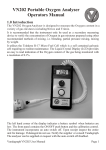
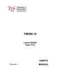
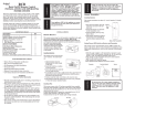
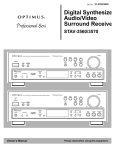
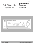
AN20MA-2 20mA Current-Voltage Interface Board
PLC’s Power
Supply
+24V
0V
AN20MA-2
DAC #1 (0-20mA)
DAC #2 (0-20mA)
DAC #3 (0-5V, buffered)
DAC #4 (0-5V, buffered)
Analog Reference (Buffered)
Analog Ground (0V)
ADC
ADC
ADC
ADC
DB15 cable
#1 (0-20mA if DIPSW-1=ON)
#2 (0-20mA if DIPSW-2=ON)
#3 (0-20mA if DIPSW-3=ON)
#4 (0-20mA if DIPSW-4=ON)
ADC #5 (0-20mA, always)
ADC #6 (0-20mA, always)
ADC #7 (0-20mA, always)
ADC #8 (0-20mA, always)
Detachable screw
terminal block.
2 Mounting Holes
(fits 1/2 DIN-KIT-2)
Figure 1 - AN20MA-2 – 2/8 channels Analog Current loop Interface Board
1. Introduction
The AN20MA-2 is designed to connect easily to a FMD or F-series PLC and converts
up to 2 channels of 0-5V analog output voltage from the PLC to 0-20mA current loop
for controlling external 0-20mA or 4-20mA devices.
AN20MA-2 also converts up to 8 channels of 0-20mA or 4-20mA analog signals from
field devices, remote sensors or other controllers into 0-5V analog input signals that
the FMD or F-series PLC accepts.
2. Physical Mounting & Wiring
Each AN20MA-2 board has two 1/8” (3mm) diameter mounting holes which allow it to
be easily mounted on copper or Nylon standoffs. Note that the two mounting holes
are spaced 4.200 inches apart, which is identical to that found on the FMD and Fseries PLCs. This means that the AN20MA-2 can be mounted readily on a DIN-Rail
using ½ pack of DIN-KIT-2 (http://www.tri-plc.com/DINkit.htm) or 1/3 pack of DIN-KIT-3.
1
AN20MA-2 Current-Voltage Interface
Installation Guide
It is easier to mount the AN20MA-2 on the left hand side of any FMD or F-series PLCs
and connect it to the PLC’s analog interface connector (DB15 female) using the 1foot (30cm) long DB15 male-to-female connecting cable (included). Once the DB15
cable is connected, the analog inputs and output signals from the PLC become
available on two detachable screw terminal blocks, making connection to field
devices much easier.
Each block of screw terminals can easily be detached from the controller body,
enabling easy replacement of the controller board when necessary. Since the
terminal block for digital I/O is inserted vertically to the board surface, you need to
remove the terminal block before you can start wiring. Use a small flat-head screwdriver and insert it underneath the terminal block, applying even pressure to raise the
terminal block until it becomes loosened from the connecting-pin strip, as shown
below:
Insulated crimp
ferrules
Tightening
screw
Connecting-pin strip
Flat-head
screw driver
Figure 2 - Removing Screw Terminal block
Although you can connect a single or multi strand wire directly to the screw terminal,
we strongly recommend using the insulated crimp ferrules to provide a good end
termination to multi-stranded wires. Using ferrules reduces the possibility of stray wirestrands short-circuiting adjacent terminals and their use is therefore highly
recommended.
3. Power Supply
The AN20MA-2 requires a 12 to 24V DC power supply to power its 20mA current loop
outputs. Please use only industrial grade linear or switching regulated power supply
from established manufacturers for best results.
You may connect it to the SAME 12 to 24V power supply as the PLC if the PLC power
supply is well regulated and provides clean current to the devices. The power supply
is to be connected to the detachable screw terminal as shown in Figure 1.
Note: the DC power supply voltage affects the maximum compliant voltage that the
20mA current loop can deliver.
2
AN20MA-2 Current-Voltage Interface
Installation Guide
Always place the power supply as close to the PLC and the interface board as
possible and use separate wires to connect the power to I/O. Keep the power supply
wire as short as possible and avoid running it alongside high-current cables in the
same cable conduit.
4. Analog Output Interface
DAC #
1&2
3&4
Analog
Ref.
Type
Voltage-to-current loop converter
Buffered voltage-follower
Buffered voltage-follower
Output Signal
0-20mA current loop
0-5V or 0-10V (same as PLC)
5V or 10V (same as PLC)
Voltage-To-Current Loop Converter Outputs
The 0-5V analog output #1 & #2 from the FMD or F-series PLCs is converted to 020mA current loop output. To interface to other types of devices that expect 4-20mA,
you simply program the DAC to output 1V to 5V.
Notes:
•
When connecting to FMD88-10 or FMD1616-10, ensure that the DAC #1 & 2
are configured for 0-5V and not 0-10V outputs.
•
When connecting to F1616-BA, the value used by SETDAC command for DAC
#1 & 2 should be limited to 0 to 2048, which will limit the output to 0-5V (since
F1616-BA can only output 0-10V DAC)
Buffered Voltage-Follower Output
AN20MA-2 provides 3 x unity-gain buffered amplifiers (aka voltage-follower) for DAC
#3, DAC #4 as well as the analog reference AVcc signal from the PLC.
Since the output voltage of a unity-gain buffered amplifier is exactly the same as the
input voltage, DAC#3 and #4 on the screw terminal follow the same voltage as the
signal output from the PLC via the DB15 connector.
However, the buffered amplifier has the advantage of providing low impedance
outputs to the screw terminal and the ability to source up to 30mA per output. This is
particularly useful for the DAC#3 and #4 from the FMD88-10 and FMD1616-10 PLCs
since these two DACs are high impedance outputs. The AN20MA-2 provides these two
analog outputs with a low impedance buffer and offers protected interface to the
fragile analog output pins of the PLC.
3
AN20MA-2 Current-Voltage Interface
Installation Guide
5. Analog Input Interface
ADC #
1– 4
5–8
Type
250 Ohm resistor, or
pass through
Signal Conversion
DIPSW 1-4 ON : 0–20mA –> 0–5V
DIPSW 1-4 OFF : no change
250 Ohm resistor
0–20mA –> 0–5V
Current Loop-to-Voltage Conversion
The simplest means of converting a 0-20mA (or 4-20mA) current loop signal to 0-5V
range is to connect a 250 ohm load to the current loop and then measure the
voltage drop across the load (20mA x 250 ohm = 5V) using the PLC’s analog input.
On the AN20MA-2 interface board, 8 x 250 ohm resistive loads are provided to
convert 8 channels of 20mA current loop input signals to voltage signals. Of these,
analog inputs #1 to #4 can optionally be disconnected from the 250 ohm resistors
by pushing the respective DIP Switch to the OFF position. E.g. if you wish to disconnect
ADC input #3 from the screw terminal block to the 250 ohm resistor, then just turn DIP
switch #3 to the OFF position. When the DIP switch is OFF the corresponding signal
from the screw terminal is directly passed through to the DB15 connector.
ADC #5 to #8, on the other hand, are hard-wired to the 250 ohm resistors and
therefore cannot be disabled (except by de-soldering the resistors). However, a low
impedance voltage source that can source more than 20mA current can still be
connected to ADC #5 to #8 even with the 250 ohm resistors in place.
Recalibration of Analog Input
Note that some of the analog inputs (e.g. ADC 7 & 8 on FMD PLCs, ADC5-8 on F2424
and ADC 1-8 on F1616-BA) are of low impedance type (20K Ohm or 40K ohm). When
a 20mA current loop is converted to 5V signal as described above, the 250 ohm
resistor is effectively connected in parallel to the input impedance. This can affect the
accuracy of the analog reading since the resulting resistance is slightly lower than 250
ohm and the converted voltage will be lower than the correct voltage.
You can correct the error by re-calibrating the analog input using the “Ethernet & ADC
Configuration Tool” and following the procedure described in the PLC User’s Manual.
4