1
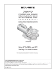
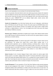
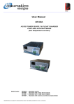
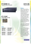
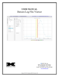
User Manual
IEXT / IEHR
70- 150 Watt DC-DC Converter
Specifications are subject to change without prior notice.
www.innovative.co.nz
09/06/15
DC>DC converters
•
•
•
•
•
•
•
•
•
Isolated input- output - chassis
Designed for industrial use
Output over voltage protection (IEXT)
Constant current limit for charging (IEXT)
Input transient/surge suppression
Short circuit protection
Reverse polarity protection
External trim pot for output voltage adjustment
Output decoupling diode and dc fail alarm
standard
♦ 24 Month Warranty
SPECIFICATIONS All specifications are typical at nominal input, full load and at 20°C unless otherwise stated.
ELECTRICAL
DC Input (nominal)
12, 24, 36, 48V
Protection - input
All models: Input fuse
PHYSICAL
Connections - In/Out
IEXT: Plug-in screw terminal block
IEHR: 'Barrier' type screw terminal
Enclosure
IEXT: Overload: constant current limit
Severe overload: shuts down when
output < 5V, power off to reset
IEHR: Hiccup mode current limit
Base: anodised aluminium
Cover: black powder coated mild steel
Indicators
Green LED for Power On
Weight
IEXT: 450g
Reverse Polarity
IEXT/LV & IEHR: input fuse
IEXT/MV & IEXT/HV: not polarity sensitive
Mounting
Transient Protection
Input varistor
Isolation
1KV DC input - output - chassis
IEXT: M5 Ø holes 164 x 46 mm, and/or:
M3 threaded inserts 164 x 66 mm
IEHR: To flat surface with brackets supplied,
M4 Ø holes.
Side mounting centres 140 x 78 mm,
End mounting centres 216 x 78 mm
Efficiency
LV: 72-80%, MV/24/48: 80-87%, HV: 85-87%
•
output
Overvoltage Protection Operates at 25% above nominal output voltage (converter shuts down - reset by power
(IEXT only)
off)
IEHR: 1.25Kg
OPTIONS
Rack mount
Converter fitted into 19” x 2U subrack
Add : +RM2U plus +REARHR6.1
Soft Start
1 second typical
DIN Rail Mount
Using DIN rail clips, code DINKIT
Output Power
IEXT: 70W continuous
IEHR: 150W continuous
Fork Hoist Use
Please contact our sales office, add option:
+FORKHOIST
Output Voltages
Refer to model table - other voltages available, please ask our sales staff
Low Temperature
Operation to -20°C, add sufix -LT
Conformal Coating
Voltage Adj. Range
Approx. ±10%, refer to model table
For harsh environments, add option:
+CONFORMAL COATING
Line Regulation
< 0.5% over input range
Load Regulation
< 0.7% open circuit to full load
Battery Charging
* Please specify output
voltage on ordering
Ripple
Typically 1% Peak-Peak
The IEXT has a constant output current limit
and is suitable for battery charging.
The IEHR does not have a constant current
limit but may be used for battery charging for
some applications.
EMC
To CISPR22:1985
Undervoltage lockout
Available on IEXT/LV models, Lockout at
10.2V, auto reset at 12.4V, add suffix -UV
Operating
Temperature
0 to 40°C; linearly derate to 50% output at
50°C
Use with laptops
Alarm contacts
Changeover, 1A 30VDC
Some laptops require a ‘SENSE’ terminal the diode is replaced with a resistor and the
D+ terminal becomes the “SENSE’ terminal.
Specifications are subject to change without prior notice.
www.innovative.co.nz
2
70-150W
Isolated DC-DC Converter
STANDARD MODEL TABLE - IEXT - 70 Watt
DC Input
MODELS*
DC Output
1
4
Voltage
Range
Voltage*
Amps
Voltage
Range
11-16
5
10
4.5 - 5.5
IEXT/LV-12P
11-16
13.8
5.0
11 - 14
IEXT/LV-18P
11-16
18
3.8
16 -20
IEXT/LV-24P
11-16
24
2.9
22-28
IEXT/LV-48P
11-16
48
1.5
43-55.2
21 - 60
8
6.5
7.6 - 9.5
IEXT/MV-12P
21 - 60
13.8
5.0
11 - 14
IEXT/MV-18P
21 - 60
18
3.8
16.6 - 20.3
IEXT/MV-24P
21 - 60
24
3.0
22-28
IEXT/MV-48P
21 - 60
48
1.5
43-55.2
IEXT/HV-12P
60 - 132
13.8
5.0
11-14
IEXT/HV-24P
60 - 132
24
3.0
22-28
IEXT/HV-48P
60 - 132
48
1.5
43-55.2
IEXT/LV-05P
*2
IEXT/MV-08P
*3
*1 Model codes without
the -P suffix do not have
diode and alarm relay fitted
*2 No overvoltage protection
*3 No input rectifier bridge
*4 Refer to terminal connections below. Output
voltage is set at +D output
except for 12V models
where the ‘+’ output is set
to 13.8V
STANDARD MODEL TABLE - IEHR - 150 Watt
DC Input
MODELS*
DC Output
1
4
Voltage
Range
Voltage *
Amps
Voltage
Range
IEHR/LV-12P
10.5-16
13.8
11.2
11-14
IEHR/LV-24P
10.5-16
24
6.2
22-28
IEHR/LV-36P
10.5-16
36
4.2
32-41.4
IEHR/LV-48P
10.5-16
48
3.2
43-55.2
IEHR/24-12P
21-40
13.8
11.2
11-14
IEHR/24-24P
21-40
24
6.2
22-28
IEHR/24-36P
21-40
36
4
32-41
IEHR/24-48P
21-40
48
3.2
43-55.2
IEHR/48-12P
40-60
13.8
11.2
11-14
IEHR/48-24P
40-60
24
6.2
22-28
IEHR/48-36P
40-60
36
4
32-41
IEHR/48-48
40-60
48
3.2
43-55.2
IEHR/HV-12P
60 - 132
13.8
11.2
11-14
IEHR/HV-24P
60 - 132
24
6.2
22-28
IEHR/HV-36P
60 - 132
36
4.2
32-41.4
IEHR/HV-48P
60 - 132
48
3.2
43-55.2
Dimensions: IEXT
180L x 82W x 37H
Dimensions: IEHR
207L x 130W x 60H
TERMINAL LAYOUTS
IEXT
IEHR
Green LED indicates output present
O
- +
NO COM NC
INPUT
ALARM CONTACTS
+D
+
-
OUTPUT
Specifications are subject to change without prior notice.
www.innovative.co.nz
3
Safety
The user is responsible for ensuring that input and output wiring segregation complies with local standards and that in
the use of the equipment, access is confined to operators and service personnel. A low resistance earth connection is
essential to ensure safety and additionally, satisfactory EMI suppression (see below).
HAZARDOUS VOLTAGES EXIST WITHIN A POWER SUPPLY ENCLOSURE AND ANY REPAIRS MUST
BE CARRIED OUT BY A QUALIFIED SERVICEPERSON.
Electrical Strength Tests
Components within the power supply responsible for providing the safety barrier between input and output are constructed to provide electrical isolation as required by the relevant standard. However EMI filtering components could be damaged as result of excessively long high voltage tests between input, output and ground. Please contact our technicians
for advice regarding electric strength tests.
Earth Leakage
Where fitted, EMI suppression circuits cause earth leakage currents which may be to a maximum of 3.5mA.
Ventilation
High operating temperature is a major cause of power supply failures, for example, a 10oC rise in the operating temperature of a component will halve its expected life. Therefore always ensure that there is adequate ventilation for the
equipment. Batteries in particular suffer shortened lifetimes if subjected to high ambient temperatures.
Water / Dust
Every effort must be made in the installation to minimise the risk of ingress of water or dust. Water will almost always
cause instant failure. The effects of dust are slower in causing failure of electronic equipment but all electrical equipment should be cleaned free of any dust accumulation at regular intervals.
Electromagnetic Interference (EMI)
Switching power supplies and converters inherently generate electrical noise. All wiring should be as short as practicable and segregated from all equipment wiring which is sensitive to EMI. Residual noise can be reduced by looping DC
wiring through ferrite cores (sleeves). These are most effective as close to the power supply as possible and as many
turns of the wire taken through the core (+ and - in the same direction) as the core will accommodate.
External fuse protection
Fuses or circuit breakers must be used in all battery circuits to protect against short circuits. External fuses should be
used for power supplies/ chargers even though they are usually internally protected.
Connection polarity
It is critical to check the polarity carefully when connecting DC devices. Some Innovative Energies models have nondestructive reverse polarity protection but usually a reverse polarity connection will result in a blown fuse or serious
damage to the device.
WARRANTY
Innovative Energies Ltd warrants its power supplies for 24 months (two years) from date of shipment against material
and workmanship defects.
Innovative Energies' liability under this warranty is limited to the replacement or repair of the defective product as long
as the product has not been damaged through misapplication, negligence, or unauthorized modification or repair.
Specifications are subject to change without prior notice.
www.innovative.co.nz
4