1
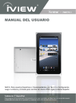
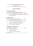
OWNER’S MANUAL
GROUP EXERCISE BIKE
Table of Contents
Important Safety Instructions……………………………………………………….…………3
Guidelines for Safe Operation…………………………………………………….…………..4
Hardware Assembly Pack……………………………………………………………………..5
Adjusting the Bike for a Proper Fit………………………………………………….………...10
Dual Function pedal……………………….………………………………..………….………11
Basic Operation / Maintenance Guidelines……………………………………….……..…..12
Parts list………………………………………………………………………………………….13
Exploded View Drawing..………………………………………………………………………16
SB702GS_1204(SL)B
2
IMPORTANT SAFETY INSTRUCTIONS
1.
READ ALL INSTRUCTIONS BEFORE USING THIS EXERCISE EQUIPENT
Use this equipment only for its intended use as described in this manual. Do not attempt
to ride this bike at high pedal speeds until you have ridden the bike for some time and
are comfortable riding at slower pedal speeds.
2.
The bike is NOT equipped with a freewheel system which means that when the flywheel
is in motion, the pedals will be in motion. Do not attempt to stop the unit by applying
backward pressure to pedals while they are turning as knee injury may occur. Do not
attempt to remove your feet from pedals while they are moving.
3.
Wait for flywheel to coast to a stop before dismounting the bike. If you want to stop the
flywheel, push down on the brake knob.
Serious injury or death may occur from over-training. Consult a medical doctor or
qualified fitness instructor to determine an exercise program appropriate for your level
4.
5.
6.
7.
8.
of fitness.
Do not attempt to turn the pedal cranks by hand. Do not touch any driving mechanism
while it is in motion as possible injury could occur.
In a home setting, keep children away from the bike when it is not in use. Keep children
and pets away from the unit while it is in use.
Do not attempt to perform dip movements on handlebars.
Never drop or insert any object into any opening of the bike.
9.
10.
Only use the bike on a stable, level floor.
Follow instructions for safe use of the equipment including proper seat position,
handlebar position, and use of foot positioning system of pedals. Do not attempt to pull
up handlebar post and seat post over the ‘MAX.’ graduation.
11.
For safe operation, allow for at least 1foot (30cm) of free space to either side of the unit
and 2 feet (60cm) of free space to the rear of the unit.
Regularly examine the bike for damage and wear. Inoperable components should be replaced
immediately or the equipment should not be used until it is repaired.
Failure to follow all guidelines may compromise the effectiveness of the exercise experience,
expose yourself (and possibly others) to injury, and reduce the longevity of the equipment.
3
GUIDELINES FOR SAFE OPERATION
WARNING!
AS THE OWNER OF THIS EXERCISE EQUIPMENT, YOU SHOULD INSIST THAT ALL
USERS FOLLOW THE SAME GUIDELINES: YOU SHOULD MAKE THIS MANUAL
AVAILABLE TO ALL USERS.
1.
Obtain a complete physical examination from your medical doctor and enlist a
health/fitness professional’s aid in developing an exercise program suitable for your
current health status.
2.
When working out for the first time, start out slowly for a minimum of five minutes. After
your muscles are warmed up, gradually increase the pedaling rate zone.
The speed and duration of your exercise program should always be subject to how you
feel. Never permit peer pressure to exceed your personal judgment while exercising.
3.
4.
5.
Overweight or severely de-conditioned individuals should be particularly cautious when
using the equipment for the first time. Even thought such individuals may not have
histories of serious physical problems, they may perceive the exercise to be far less
intense than it really is, resulting in the possibility of overexertion or injury.
Proper installation and regular maintenance are required to ensure user’s safety.
Maintenance is the sole responsibility of the owner.
4
Hardware Assembly Pack
#49. 5/16" × 1.5T_
Split Washer (4pcs)
#88. 5/16" × 5/8"_
Button Head Socket Bolt (4pcs)
#48. 5/16" × 16 × 1T_
Flat Washer (4pcs)
#91. M5 × 10m/m_
Phillips Head Screw (2pcs)
#82. 3/8"
Cap Nut (4pcs)
#83. 3/8" × 23 × 1.5T_
Curved Washer(4pcs)
#81.3/8" × 3-1/2"_
Carriage Bolt (4pcs)
#85.14/15m/m_Wrench(1pc)
#86. M5_Combination M5 Allen Wrench
& Phillips Head Screw Driver(1pc)
5
STEP 1
•
Stabilizer Assembly
Install the front and rear stabilizers with four 3/8"×3-1/2" carriage bolts (81), four 3/8" curved
washers(83) and four 3/8" cap nuts(82). The front and rear stabilizer are different. Be sure to
assemble the stabilizer with the wheels onto the front of the bike.
6
STEP 2
•
Rear Cover
Install the rear stabilizer cover with two M5 x 10mm screws (91).
7
STEP 3
Handlebar and Drink Holder
•
Install the handlebars with four 5/16" x 15mm bolts (88), 5/16" split washers (49) and four
5/16” flat washers (48). Tighten the bolts securely.
•
Install the drink holder to the handlebars by loosening the thumb screw, clamp to the
handlebars and re-tighten the thumb screw.
8
STEP 4
•
Pedal Assembly
Install the Left (25L) and Right (25R) pedals to the crank arms. Please note that the Left pedal
has a reverse threaded bolt and needs to be tightened in a counterclockwise direction. The
pedals are identified by either an R or L stamped into the end of the bolt.
Right Pedal
Left Pedal
9
ADJUSTING THE BIKE FOR A PROPER FIT
Take some time to learn how to properly adjust the bike to your body; it will make your workouts
more pleasant and a safer experience too. Riding the bike when it is incorrectly adjusted can result
in discomfort and increase your risk of injury.
Adjustment of Seat Position:
Seat Height Adjustment
1. Standing next to the bike, adjust seat until it is about hip height.
2. Rotate crank arms until the pedals are in the vertical position: 12 and 6
o’clock.
3. Place your foot in toe cage of pedal closest to the floor and mount the
bike. Ensure that the ball of your foot is over the center of pedal. Your leg
should be slightly bent at the knee, about 5 degrees.
4. If your leg is too straight or your foot cannot touch pedal you will need to
lower seat height. If your leg is bent too much you will need to raise seat
height.
5. Dismount the bike. Loosen the quick release lever on seat post and adjust up or down as
necessary.
6. When seat is in the desired position, tighten the quick release to secure the seat post.
7. Note the final position mark on the seat post for future reference.
Seat Forward/Aft Adjustment
1. Sit on bike with crank arms in the 3 and 9 o’clock positions. For road bike
training, a proper forward/aft position of the seat is achieved when small
bump at the top of the shin is above pedal axle.
2. Dismount the bike. Loosen the quick release under the seat and slide the
seat forward or backward as desired; then tighten the quick release.
Handlebar Adjustment:
Handlebar Height Adjustment
1. The Handlebar height is a matter of preference. Start with a handlebar height that is the same
as the seat’s height. Adjusting the handlebar higher will give the rider a more upright position;
lower will result in a more crouched position.
2. Raise or lower the handlebar by loosening quick release on handlebar
post and adjust by sliding the handlebar mount up or down as desired.
Then tighten the quick release to secure the handlebar post. Note the
final position mark on handlebar post for future reference.
Adjustment of Handlebar’s Forward/Aft Position
1. Loosen the quick release under the handlebar and slide the handlebar
forward or backward as desired. Suitable forward/aft position should allow the rider to
comfortably grasp the handlebar with a slight bend at the elbow.
2. Tighten the quick release to secure the handlebar assembly.
10
DUAL FUNCTION PEDAL
ADJUSTING THE PEDAL STRAPS
Place your feet in between the aluminum surface of the pedal and the nylon foot strap that
wraps around it. If the opening is too narrow, depress the spring loaded clasp with one hand
and pull on the nylon strap with the other to increase the opening area. If it is too loose or to
tighten the strap, depress the spring loaded clasp, then pull on the open end of the nylon
strap until the strap is snug around each foot.
11
BASIC OPERATION
Now that you have established a proper riding position, take a few minutes to ride the bike and
determine that your position is comfortable. Start pedaling at a slow pace with your toes and
knees pointed directly forward. Hold the handlebar lightly and in a position that allows your
shoulders and upper body to relax. Pedal easily, at a low resistance until you feel confident that
you could ride in that position for the duration of your workout.
WARNING!
IF AT ANY TIME DURING YOUR WORKOUT, YOU FEEL CHEST PAIN, EXPERIENCE SEVERE
MUSCULAR DISCOMFORT, FEEL FAINT, OR ARE SHORT OF BREATH, STOP EXERCISING AT
ONCE. IF THE CONDITION PERSISTS, YOU SHOULD CONSULT YOUR MEDICAL DOCTOR
IMMEDIATELY.
1.
2.
3.
Pedaling resistance is controlled by the tension knob. Resistance can be changed at any
time by turning tension knob: clock-wise for more resistance; counterclockwise for less
resistance.
To apply the brake, press down on the tension knob.
Before dismounting, apply the brake to stop flywheel, or increase resistance and let
flywheel come to a stop.
MAINTENANCE GUIDELINES
MAINTENANCE SCHEDULE
LUBRICANT
PART
RECOMMENDED ACTION
FREQUENCY
CLEANER
Pedals
Ensure that pedals are tight in Before each use
N/A
N/A
crank arms; that all screws on
pedals are tight; and that the
pedal straps are not frayed
Frame
Wipe down by using a soft
Daily
Water
N/A
damp clean cloth
Flywheel
Wipe down by spraying on a
Weekly
WD-40
N/A
rag and applying a light coat
spray.
to sides of the flywheel
Brake Pad Inspect for excessive wear or
Weekly
N/A
3-IN-ONE Oil or
a dry leather brake pad
10W oil. Do not
use silicone-based
lubricants
1. Do not service internal parts of pedals. If they are found to be worn internally, we recommend
replacing the pedal.
2. Use of lubricants or cleaning solutions other than those so specified will result in diminished
performance and a shorter life span for that part.
12
PARTS LIST
No.
Description
Qty
1
Main Frame
1
2
Front Stabilizer
1
3
Rear Stabilizer
1
4
Handlebar Post
1
5
Seat Post
1
6
Handlebar
1
7
Sliding Seat Mount
1
8
Sliding Handlebar Mount
1
9
Brake Pad Bracket
1
10
Brake Pad - Wool Felt
1
11
Bushing
1
12
Nut
1
14
Spring
2
16
Brake Tension Knob
1
18
M6 × 15mm_Phillips Head Screw
4
19
8 × 40m/m_Quick Release lever
2
20
8 × 25m/m_Quick Release Lever
2
21
Aluminum Locking V-Blocks
4
22
5/16" × 35 × 3.0T_Flat Washer
1
25
Pedal Set
1
26
Anti-Rotation Washer
1
27
Seat
1
29
5 × 16m/m_Tapping Screw
2
30
3.5 × 12m/m_Sheet Metal Screw
3
31
Flywheel
1
32
Bearing Housing
2
33
Flywheel Axle
1
34
Woodruff Key
1
35
Flywheel Pulley
1
36
5/16" × 3/4"_Button Head Socket Bolt
1
37
5/16" × 20 × 3.0T_Flat Washer
1
38
5/16" × 3/4"_Button Head Socket Bolt
6
39
M6 × 10L_Phillips Head Screw
6
40
Belt
1
41
Drive Pulley
42
Crank Arm
1
43
(L)
Crank Arm(R)
1
44
Crank Arm Dust Cap
2
(25L.25R)
1
13
No.
Description
Qty
45
Crank Axle
1
46
5/16" × 1/2"_Button Head Socket Bolt
5
48
5/16" × 16 × 1T_Flat Washer
4
49
5/16" × 1.5T_Split Washer
4
50
Transportation Wheel
2
53
Rubber Foot
4
54
3/8"_Nut
4
55
Stabilizer End Cap
4
56
End Cap, Eye Tube
2
57
Plastic Slide Insert, Eye Tube
2
58
Bottom End Cap, Eye Tube
2
59
Rear Stabilizer Cover
60
Chain Cover
1
61
(Outer)
Chain Cover(Inner)
1
62
Flywheel Fender
1
63
Pulley Cover
1
64
6004_Bearing (NSK)
2
65
6203_Bearing
2
66
6004_Bearing (TMT)
2
67
Ø17_C Ring
1
68
Ø20_C Ring
3
69
1/4" × 3"_Hex Head Bolt
1
70
1/4"_Hex Head Bolt
1
71
1/4" × 5.5T_Nyloc Nut
1
72
3/8" × 2"_Flat Head Socket Bolt
2
73
25.5 × Ø16_Star Washer
1
74
Idler Axle
1
75
Idler Adjustment Carriage Bolt
1
76
Console Assembly
1
77
Foam Stop, Handlebar Eye Tube
1
78
Ø5/16" × 23 × 2.0T_Flat Washer
1
79
3/8" × 19 × 1.5T_Flat Washer
2
80
M10 ×
P1.25_Nut
2
81
3/8" × 3-1/2"_Carriage Bolt
4
82
3/8"_Cap Nut
4
83
3/8" × 23 × 1.5T_Curved Washer
4
84
M5 × 12m/m_Tapping Screw
2
85
14/15m/m_Wrench
1
86
M5_Combination M5 Allen Wrench & Phillips Head Screw Driver
1
1
14
No.
Description
Qty
87
Drink Bottle(Optional)
1
88
5/16" × 5/8"_Button Head Socket Bolt
4
89
M5 × 10m/m_Socket Head Cap Screw
2
90
Ø5 × 10m/m_Tapping Screw
4
91
M5 × 10m/m_Phillips Head Screw
2
92
M5_Speed Nut Clip
2
93
M5 × 10m/m_Tapping Screw
7
94
Spring
1
95
Fixing Pin
1
96
Safety Sleeve
1
97
5/16" × 1"_Button Head Socket Bolt
1
98
Sleeve Bushing
1
99
3/8" × 3/4"_Button Head Socket Bolt
2
100
3/8" × 21 × 2T_Flat Washer
2
107
Ø8 × Ø12 × 1.0T_Flat Washer
1
15
Exploded View Drawing
16