1
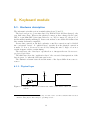
A microcontroller-based temperature
regulation
Digital interfacing and software
∗
Jochen Ott
I20/2943/05
July 2006
Supervisor: Dr. Dmitry Zaroslov
∗ This
is a revised edition to account for some last-minute changes in the software which
have not been documented in the original version.
Contents
1. Introduction
1.1. Microcontroller usage in control engineering . . . . . . . . . . . . .
1.2. This project . . . . . . . . . . . . . . . . . . . . . . . . . . . . . . .
1.3. About this report . . . . . . . . . . . . . . . . . . . . . . . . . . . .
2. Software architecture
2.1. Modularization . . .
2.2. Interrupts . . . . . .
2.2.1. Interrupts and
2.3. Module overview . .
. . . . . . . . .
. . . . . . . . .
the Z8Encore!
. . . . . . . . .
3. Timer module
3.1. Hardware description . . . . . .
3.2. Implementation . . . . . . . . .
3.2.1. Disabled interrupts . . .
3.2.2. Race conditions . . . . .
3.2.3. Timer counter behaviour
3.3. Summary . . . . . . . . . . . .
.
.
.
.
.
.
.
.
.
.
.
.
.
.
.
.
.
.
.
.
.
.
.
.
.
.
.
.
.
.
.
.
.
.
.
.
.
.
.
.
.
.
.
.
.
.
.
.
.
.
.
.
.
.
.
.
.
.
.
.
.
.
.
.
.
.
.
.
.
.
.
.
.
.
.
.
.
.
.
.
.
.
.
.
.
.
.
.
.
.
.
.
.
.
.
.
.
.
.
.
.
.
.
.
.
.
.
.
.
.
.
.
.
.
.
.
.
.
.
.
.
.
.
.
.
.
.
.
.
.
.
.
.
.
.
.
.
.
.
.
.
.
.
.
.
.
.
.
.
.
.
.
.
.
.
.
.
.
.
.
.
.
.
.
.
.
.
.
.
.
.
.
.
.
.
.
.
.
5
5
6
6
.
.
.
.
7
7
8
9
10
.
.
.
.
.
.
12
12
12
15
16
17
18
4. Callback module
4.1. Usage . . . . . . . . . . . . . . . . . . . . . . .
4.2. Implementation . . . . . . . . . . . . . . . . . .
4.2.1. Timer wrap-round . . . . . . . . . . . .
4.2.2. Multiple deadlines . . . . . . . . . . . .
4.2.3. Adding callbacks . . . . . . . . . . . . .
4.2.4. Adding callbacks from within a callback
4.2.5. Callback behaviour after blocking . . . .
4.2.6. Module initialization . . . . . . . . . . .
.
.
.
.
.
.
.
.
.
.
.
.
.
.
.
.
.
.
.
.
.
.
.
.
.
.
.
.
.
.
.
.
.
.
.
.
.
.
.
.
.
.
.
.
.
.
.
.
.
.
.
.
.
.
.
.
.
.
.
.
.
.
.
.
.
.
.
.
.
.
.
.
.
.
.
.
.
.
.
.
.
.
.
.
.
.
.
.
19
20
20
24
25
26
29
29
30
5. Display module
5.1. Hardware . . . . . . . . . . . .
5.1.1. The seven-segment digits
5.1.2. Multiplexing . . . . . . .
5.1.3. Digit patterns . . . . . .
.
.
.
.
.
.
.
.
.
.
.
.
.
.
.
.
.
.
.
.
.
.
.
.
.
.
.
.
.
.
.
.
.
.
.
.
.
.
.
.
.
.
.
.
31
31
31
32
32
2
.
.
.
.
.
.
.
.
.
.
.
.
.
.
.
.
.
.
.
.
.
.
.
.
.
.
.
.
.
.
.
.
.
.
.
.
Contents
5.2. Software . . . . . . . . . . .
5.2.1. Digit updating . . .
5.2.2. Setting the display .
5.2.3. Module initialization
5.2.4. Blinking . . . . . . .
.
.
.
.
.
.
.
.
.
.
.
.
.
.
.
.
.
.
.
.
.
.
.
.
.
.
.
.
.
.
.
.
.
.
.
.
.
.
.
.
.
.
.
.
.
.
.
.
.
.
.
.
.
.
.
.
.
.
.
.
.
.
.
.
.
.
.
.
.
.
.
.
.
.
.
.
.
.
.
.
.
.
.
.
.
.
.
.
.
.
.
.
.
.
.
.
.
.
.
.
.
.
.
.
.
.
.
.
.
.
34
34
35
36
37
6. Keyboard module
6.1. Hardware description . . . . . . .
6.1.1. Physical layer . . . . . . .
6.1.2. Data layer . . . . . . . . .
6.1.3. Application layer . . . . .
6.2. Implementation . . . . . . . . . .
6.2.1. Making infinite loops finite
.
.
.
.
.
.
.
.
.
.
.
.
.
.
.
.
.
.
.
.
.
.
.
.
.
.
.
.
.
.
.
.
.
.
.
.
.
.
.
.
.
.
.
.
.
.
.
.
.
.
.
.
.
.
.
.
.
.
.
.
.
.
.
.
.
.
.
.
.
.
.
.
.
.
.
.
.
.
.
.
.
.
.
.
.
.
.
.
.
.
.
.
.
.
.
.
.
.
.
.
.
.
.
.
.
.
.
.
.
.
.
.
.
.
39
39
39
42
42
43
46
7. Temperature module
7.1. Hardware description . . . . . . . . . . . . . . . . . . . . . . . . . .
7.2. Implementation . . . . . . . . . . . . . . . . . . . . . . . . . . . . .
48
48
48
8. Heater module
8.1. High power switching with triacs . . . . . . . . . . . . . . . . . . .
8.2. From two to many . . . . . . . . . . . . . . . . . . . . . . . . . . .
8.3. Implementation . . . . . . . . . . . . . . . . . . . . . . . . . . . . .
50
50
51
52
9. Controller module
54
10.User Interface module
10.1. UI description . . . . . . . . . . . . . . . . . . . . . . . . . . . . . .
10.2. Implementation . . . . . . . . . . . . . . . . . . . . . . . . . . . . .
56
56
56
11.Main module
11.1. Failure checking . . . . . . . . . . . . . . . . . . . . . . . . . . . . .
11.1.1. Watchdog . . . . . . . . . . . . . . . . . . . . . . . . . . . .
11.1.2. Temperature checking . . . . . . . . . . . . . . . . . . . . .
60
61
61
62
A. A mathematical model for the heater-sample-system
A.1. Proportional heating . . . . . . . . . . . . . . . . . . . . . . . . . .
A.2. Computer simulation . . . . . . . . . . . . . . . . . . . . . . . . . .
65
66
67
B. Additional timer information
B.1. Bugs . . . . . . . . . . . . . . . . . . . . . . . . . . . . . . . . . . .
B.2. Beware of traps . . . . . . . . . . . . . . . . . . . . . . . . . . . . .
70
70
72
C. The static-frames bug
74
3
Contents
D. Keyboard scancodes
78
E. Reducing code size
E.1. Code size measurements . . . . . . . . . . . . . . . . . . . . . . . .
E.2. Example: timer module optimization . . . . . . . . . . . . . . . . .
79
80
80
F. Single bit techniques
F.1. Bit-shifting . . . . . . .
F.2. Bit-wise logical operators
F.3. Bit-wise reading . . . . .
F.4. Bit-wise writing . . . . .
.
.
.
.
83
83
84
84
84
.
.
.
.
.
.
.
.
.
.
.
.
.
.
.
.
.
.
.
.
.
.
.
.
.
86
86
87
87
87
88
88
88
90
90
90
91
91
91
92
92
92
93
93
93
93
93
93
94
94
95
G. Code listings
G.1. common.h . . . . . . .
G.2. Timer module . . . . .
G.2.1. timer.h . . . . .
G.2.2. timer.c . . . . .
G.3. Callback module . . .
G.3.1. callback.h . . .
G.3.2. callback.c . . .
G.4. Display module . . . .
G.4.1. display.h . . . .
G.4.2. display.c . . . .
G.5. Keyboard module . . .
G.5.1. keyboard.h . .
G.5.2. keyboard.c . . .
G.6. Temperature module .
G.6.1. temp.h . . . . .
G.6.2. temp.c . . . . .
G.7. Controller module . . .
G.7.1. controller.h . .
G.7.2. controller.c . .
G.8. User interface module .
G.8.1. ui.h . . . . . . .
G.8.2. ui.c . . . . . . .
G.9. Main module . . . . .
G.9.1. main.h . . . . .
G.9.2. main.c . . . . .
.
.
.
.
.
.
.
.
.
.
.
.
.
.
.
.
.
.
.
.
.
.
.
.
.
.
.
.
.
.
.
.
.
.
.
.
.
.
.
.
.
.
.
.
.
.
.
.
.
.
.
.
.
.
.
.
.
.
.
.
.
.
.
.
.
.
.
.
.
.
.
.
.
.
.
.
.
.
.
.
.
.
.
.
.
.
.
.
.
.
.
.
.
.
.
.
.
.
.
.
.
.
.
.
.
.
.
.
.
.
.
.
.
.
.
.
.
.
.
.
.
.
.
.
.
.
.
.
.
.
.
.
.
.
.
.
.
.
.
.
.
4
.
.
.
.
.
.
.
.
.
.
.
.
.
.
.
.
.
.
.
.
.
.
.
.
.
.
.
.
.
.
.
.
.
.
.
.
.
.
.
.
.
.
.
.
.
.
.
.
.
.
.
.
.
.
.
.
.
.
.
.
.
.
.
.
.
.
.
.
.
.
.
.
.
.
.
.
.
.
.
.
.
.
.
.
.
.
.
.
.
.
.
.
.
.
.
.
.
.
.
.
.
.
.
.
.
.
.
.
.
.
.
.
.
.
.
.
.
.
.
.
.
.
.
.
.
.
.
.
.
.
.
.
.
.
.
.
.
.
.
.
.
.
.
.
.
.
.
.
.
.
.
.
.
.
.
.
.
.
.
.
.
.
.
.
.
.
.
.
.
.
.
.
.
.
.
.
.
.
.
.
.
.
.
.
.
.
.
.
.
.
.
.
.
.
.
.
.
.
.
.
.
.
.
.
.
.
.
.
.
.
.
.
.
.
.
.
.
.
.
.
.
.
.
.
.
.
.
.
.
.
.
.
.
.
.
.
.
.
.
.
.
.
.
.
.
.
.
.
.
.
.
.
.
.
.
.
.
.
.
.
.
.
.
.
.
.
.
.
.
.
.
.
.
.
.
.
.
.
.
.
.
.
.
.
.
.
.
.
.
.
.
.
.
.
.
.
.
.
.
.
.
.
.
.
.
.
.
.
.
.
.
.
.
.
.
.
.
.
.
.
.
.
.
.
.
.
.
.
.
.
.
.
.
.
.
.
.
.
.
.
.
.
.
.
.
.
.
.
.
.
.
.
.
.
.
.
.
.
.
.
.
.
.
.
.
.
.
.
.
.
.
.
.
.
.
.
.
.
.
.
.
.
.
.
.
.
.
.
.
.
.
.
.
.
.
.
.
.
.
.
.
.
.
.
.
.
.
.
.
.
.
.
.
.
.
.
.
.
.
.
.
.
.
.
.
.
.
.
.
.
.
.
.
.
.
.
.
.
.
.
.
.
.
.
.
.
.
.
.
.
.
.
.
.
.
.
.
.
.
.
.
.
.
.
.
.
.
.
.
.
.
.
.
.
.
.
.
.
.
.
.
.
.
.
.
.
.
.
.
.
.
.
.
.
.
.
.
.
.
.
.
.
.
.
.
.
.
.
.
.
.
.
.
.
.
.
.
.
.
.
.
.
.
.
.
.
.
.
.
.
.
.
.
.
.
.
.
.
.
.
.
.
.
.
.
.
.
.
.
.
.
1. Introduction
1.1. Microcontroller usage in control engineering
Microcontrollers are widely used to solve many different control engineering problems in industry. With “control engineering problem”, I mean the problem to vary
certain system parameters (such as pressure, temperature, humidity, rotation frequency, concentration of a chemical,. . . ) in a desired way (keeping them constant,
for example).
The solution involves measurement of those parameters via sensors and a decision
for the values of some output parameters which are passed to some actuator (such
as pumps, heaters or coolers, valves) that change the system parameters in the
desired way.
Microcontrollers have two major advantages over traditional (purely analog) circuits:
Complex problems involving many sensors and actuators are very difficult to
solve with an analog circuit. As microcontrollers are programmable, they can
perform almost arbitrary complex calculations to yield the desired result.
Using a micorcontroller is very flexible for future changes: whereas a analog
circuit would have to be redesigned (and re-implemented) in most cases if the
system is changed (for example, more sensors and actuators, or a modified
system behaviour to actuator parameters), in a microcontroller-based system,
often only very little hardware has to be changed and the major changes are
to be done in the software of the microcontroller.
Mainly the second point is important, as it leads to faster development time and is
often cheaper.
Of course, there are also some new problems when using a microcontroller:
Analog-digital interfacing:
As the sensor and actuator parameters will be
analog in most applications, this “analog part” of the problem has to be
interfaced with the microcontroller, the “digital part”. In some cases, this
is not easy, but many standard and well-tested solutions for most common
problems exist.
Software: Whereas there will most likely be much less hardware to design,
software has to be written for the microcontroller for which the main requirement is reliability. Writing reliable software is not as trivial as it might seem,
5
1. Introduction
even in simple projects like this (as will become clear in the ongoing of the
report).
1.2. This project
In this project, the control task is to keep a constant, user-defined temperature at
a certain area in space. As sensor, a temperature sensor (placed just at that point)
is used, the only actuator is a heater at some distance from the sensor.
Both the temperature sensor and the heater are connected to the microcontroller.
The user should be able to set a target temperature and to view the current temperature. Fur this purpose, a display and a keyboard are connected to the controller.
Whereas display and keyboard can be considered as digital devices, the connection
of the other devices falls under the mentioned problem of “analog-digital interfacing”.
This report mainly discusses the “digital part”: the display, the keyboard and
the software for the microcontroller. Analog hardware issues are only covered as far
as they are necessary for a general understanding of the rest. They are discussed in
detail in two other project reports referring to the same overall project in [3] and
[4].
1.3. About this report
If reading the most recent version of the code, it might often seem much more
complicated than necessary and the solutions sometimes used might seem arbitrary
and not logical at all, especially if the reader has only little programming experience.
I have tried to keep things simple and to use the best solution to problems if there
is more than one. To make those points clear, I did not only describe the code in
its most recent version but also the development process itself that led to it: from
the first ideas of how the code could look like — which does not always work as
desired — via the problems, corrections and refinements to the result as seen in the
code listings in section G.
I tried to keep my thought general where it makes sense: Some of the modules
are generic in the sense that they do not provide a solution to problems specific to
this project but can be useful in other microcontroller projects as well.
I have tried to explain the ideas and the code in great detail but I do not cover
all implementation details, such as the precise use of configurations bits of microcontroller hardware. This is documented in [6]. Therefore, if this report is used as
basis for other projects, that document should be read. But keep in mind that it
is incomplete or unclear in many points, and contains some severe errors of which
the ones detected while working on this project are mentioned in this report.
6
2. Software architecture
2.1. Modularization
Writing programs (whether for microcontroller or for another purpose), one often
starts by writing a small parts — implementing only a small set of features — and
extending it step by step until all desired features are implemented. If done with
care, that can lead to reasonable results but more often the result is a program that
is hard to understand, hard to find errors and re-use of parts of the code for other
projects is almost impossible.
To address those issues, common programming practice1 is to split up the program
into smaller parts, called modules, each having a well-defined task (a sub-problem to
solve). Those modules can be accessed by other modules through a set of functions
called interfaces of the module.
Benefits of this modularization are:
Reducing complexity: The individual modules are small and each having a
well-defined behaviour and interface. By defining these during design, some
problems and traps can be identified and addressed at an very early stage of
software development.
Easier testing: As each module has a well-defined behaviour, it is possible to
write small test programs which test the behaviour and functionality of only
one module. If the modules are independent enough (and do not access the
same hardware), testing and correcting individual modules eliminates the vast
majority of bugs.
Reusability: When splitting up the problem into sub-problems one often notices that some sub-problems (which are addressed in the modules) are very
common and arise for very different original problems. Therefore, some modules can be re-used for other projects.
Maintainability: Suppose, a piece of hardware has to be changed in the setup
(the temperature seonsor, for instance). Having only one module which does
the interaction with it (along with a reasonable interface), all what has to be
changed in the program is only one module. With one large program, it is
common that the hardware is accessed at many different places, making such
changes much more difficult and error-prone.
1
indeed so common that hardly anyone ever writes about that subject in this generality
7
2. Software architecture
Those benefits can also be understood as goals of modularization: The concept
of modularization itself does not dictate how exactly to split up a program into
modules (it just suggests to do it at all). Therefore, when deciding for a specific
modularization, it is important to keep those goals in mind. For example, the
reusability is only given if the interface defined is general enough for other (future)
programs as well and not too special for the single problem to be solved here.
There are not many disadvantages to this concept. One disadvantage that should
be considered here is that modularization often produces an overhead but if carefully
taken into consideration, this is very small or even can be totally avoided in most
cases.
2.2. Interrupts
Interrupts are a common way for hardware devices (and for different software modules) to communicate to the processor that some event has occured. They provide
a way of interrupting the normal program flow of the processor and executes a
special routine, called interrupt routine. As interrupts are actively signalled to the
processor (rather than the processor has to check regularly if some external event
has occured), this concept allows the processor to react very fast to some conditions
which require immediate handling. For example, the keyboard driver has to react
to a falling clock signal (which is connected to an input pin) in under 30 s. Such
timing restrictions would be very hard to fulfil if the processor/the main program
itself had to check this input pin regularly.
If the interrupt routine can interrupt the program flow at any point, even within
other interrupt handling code (probably handling the very same interrupt), race
conditions can occur, that is, the routine accesses the same data as an interrupt
routine leaving the data in an inconsistent state which — when read by the other
routine — can have undesired effects. Therefore, it is important to design the
interrupt routines carefully keeping that in mind: one should check every data access
in an interrupt routine on whether this data could be manipulated by the “normal
(interrupted) program”2 and check those concurrent access for possible problems.
Whenever a variable is accessed (that is, it is read from or written to) from within
an interrupt, one should keep in mind the problem that the interrupt might have
occured during the variable is currently used (i.e. just before or after the interrupt)
during the normal program and the variable might represent an inconsisent state
in either the interrupt routine or the normal program.
To solve this problem at least for some cases, it is possible to globally disable3 (or
µ
2
In the text, the term “normal program” is used to denote the interrupted program as opposed
to the “interrupt routine”. Note that in general it is not possible to say from a piece of code
whether it belongs to the one or the other type as some routines could be used in both contexts
and even interrupts can be interrupted, creating a hierarchy of “normal programs”
3
that is, interrupt processing is disabled for all interrupts as opposed to disable or enable par-
8
2. Software architecture
delay) interrupts. That can be used if an interrupt would have access to inconsistent
data (or it would make inconsistent changes). In most implementations, interrupts
are globally disabled at the beginning of an interrupt routine thus preventing interrupt routines from getting interrupted again (what can lead to race conditions
pretty easily).
If interrupt processing is re-enabled (for example, at the end of an interrupt
routine), any interrupt which occured in the meantime is processed immediately (if
any).
Considering the potential problems with data access in interrupt routines, it is a
good idea to keep the interrupt routines as small and simple as possible, avoiding
both race conditions and further interrupt processing (as no further interrupts are
being processed within an interrupt).
2.2.1. Interrupts and the Z8Encore!
Interrupts are managed by an external interrupt controller, the IRQ controller
which keeps track of interrupts to be processed: For each possible interrupt, it
saves one bit (in the IRQx registers) indicating whether the interrupt routine for
this interrupt should be processed (the interrupt is then said to be pending), or not.
During typical operation, interrupt processing is enabled and interrupts are processed immediately. Therefore, IRQx normally is zero. If an interrupt occurs if
interrupt processing is disabled, the corresponding IRQx-bit is set to 1 and as soon
as interrupt processing is enabled again, the pending interrupts are processed.
The IRQ controller supports three different interrupt priorities: if two interrupts
are pending at the same time, the interrupt of higher priority is processed first.
Interrupt processing can be thought of the following way4 :
1. Set the pending-bit for this interrupt.
2. Lookup whether interrupt processing is enabled for this interrupt (in the special registers IRQxENH and IRQxENL) and abort processing if not.
3. Clear the pending-status for the interrupt.
4. Disable interrupt processing.
5. Call the installed interrupt routine (looking up the interrupt vector table
which resides at a fixed memory location).
6. On returning from the interrupt routine, enable interrupt processing.
7. Execute the normal program from where it was interrupted.
4
ticular interrupts
Some details (as saving the instruction pointer) are left out as they are not necessary for an
general understanding.
9
2. Software architecture
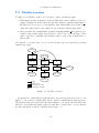
2.3. Module overview
To improve readability of the code, following coding conventions apply:
1. Each function name is prefixed by the module name and an underscore (for example, all functions in the timer module have names beginning with timer ).
In that way, it is easy to see in which module which function is defined and
using the same name for two functions by accident is almost impossible.
2. Every module has an initialization function <modulename> init (with no parameter and return value) that should be called once at the startup of the
microcontroller to initialize the hardware and to restore the default state of
the module.
If a variable or another piece of code is cited in the text, it is typeset in a fixed
width font type.
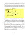
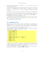
sensor
temp
display
controller
display
ui
heater
callback
keyboard
heater
timer
keyboard
timer1
timer0
uses
calls back
software module
hardware module
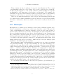
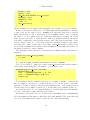
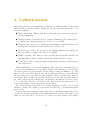
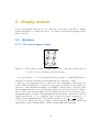
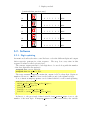
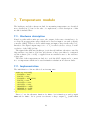
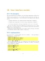
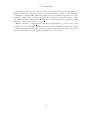
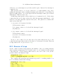
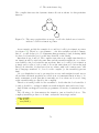
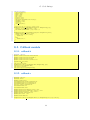
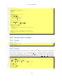
Figure 2.1.: Module overview.
A general idea of what the program should do was already given in section 1.2. In
figure 2.1, an overview of all modules, their connection and hardware usage is given.
The main module is not shown as its task is simply to set up all other modules and
therefore very small and simple (but it would have connections to every software
module and therefore hard to include in the figure. . . ).
10
2. Software architecture
The task of each module is given briefly here. A complete description is found in
the sections 3–11.
The timer module provides a 32-bit tickcount value which reflects the time
passed since start of the microcontroller and can be used by other modules
for timing information.
The callback module provides an easy way for other modules to call back cer-
tain functions either once after a given time or regularly at a certain frequency.
This provides some decentralization: instead of the main module calling the
different modules, they get called from the callback module – with predictable
timing.
The display module allows easy usage of the display for other modules that
only need to specify the number to output.
The keyboard module reads data sent by the keyboard.
The temperature module reads the voltage from the A/D converter and converts it to a temperature.
The controller module reads the temperature and calculates (using the userset target temperature) an appropriate new value for the heater level which
is passed to the heater module.
The heater module takes the current heater level and creates an appropriate
output for the triac driver at an output pin.
The user interface module displays reads keys pressed by the user and updates
the display and the target temperature accordingly.
The main module sets up all other modules and ensures that they are executed
regularly. It also contains some measures limiting damage in case of software
or hardware failures.
11
3. Timer module
For many problems, it is necessary to know how much time has passed between two
events E1 and E2 . For example, one could want to measure a low frequency at an
input pin by measuring the time between two consecutive falling edges.
In this project, the main application for the timer module is the callback module
that is described in section 4.
3.1. Hardware description
The microprocessor used for this project has two built-in timers (referred to as
timer0 and timer1 ) with a variety of running modes which makes it suitable for this
task.
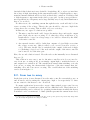
Each timer has a 16-bit counter C and a 16-bit reload value RL which each are
stored as two bytes: one of them representing the highest 8 bits, the other the
lowest 8 bits of the 16-bit values. In the operation mode used here, the continuous
mode, the timer increments the counter by one at each system clock period. If the
counter reaches the reload value, an interrupt is fired, the counter is reset to the
value 1 and incrementing continues.
As the system clock is too fast for many purposes — using a system clock of 5MHz
directly would produce an interrupt after a maximum of 0.013s — it is possible, to
prescale this frequency by a factor of 2p where 0 ≤ p ≤ 7, that is, to divide the
system clock frequency by 2p and use the result as the timer incrementing frequency.
SC
where
The frequency in which an interrupt is fired is therefore given by RL×P
S
SC is the system clock frequency, and P S is the prescale factor. The amount of
time to the first interrupt depends on the initial value of C.
3.2. Implementation
Before discussing the implementation in detail, see sections B for additional information on how to use the timer from within a program. The essential results
are
Care has to be taken if reading or writing the timer counter (or writing the
reload value) while the timer is running. Reading the counter is only possible
by reading the high byte first (even if the timer is not running). The same is
true for writing the reload value.
12
3. Timer module
The simulator has many bugs regarding the behaviour of the timer which
makes it almost impossible to test the software before loading the final program to the microcontroller.
The original problem to be solved was mesuring the time passed between two
events E1 and E2 , or — to be more specific — between two lines of code.
To do that, one could configure a timer to zero at E1 and enable the counting.
Reading the value at E2 then gives the time passed (considering the prescale value
and system clock frequency). However, there are two major problems with this
implementation:
1. Only short intervals of time can be measured before the counter reaches the
maximum value of 0xFFFF and starts counting from 0x0001 again: If the
system clock is around 5MHz, this occurs about every 13ms (if a pre-scale of
1 is used). This is too short for many applications.
2. In general, one may wish to measure time intervals at the same time, which is
not possible with the explained setup: if one wants to measure both the time
passed between E1 and E2 and between F1 and F2 and F1 occurs between E1
and E2 , the timer is reset at F1 and the time interval calculated at E2 leads
to a wrong result.
To address point 2., we define the function timer gettickcount (which can be
called by other modules) passed since an arbitrary point in the code; this is enough
to measure time intervals.
The other issue can be solved by introducing a 16-bit-variable rounds which
counts how often the counter already hit the reload value. The reload value is set
to 0x0000 to have the maximum time between two hits: according to [8],1 each
round then lasts for 65536 clock ticks, and therefore, the total number of ticks is
calculated by rounds * 65536 + counter where counter is the current value of
the timer counter. The result of this calculation will be a 32-bit-value which I call
the tickcount or T .
T will wrap around after about 859s (if prescale is set to 1). As the number of
rounds is to be counted, the timer should be configured to fire an interrupt if the
counter reaches the reload value. The timer is configured in continuous mode, and
an interrupt routine for the timer interrupt is installed at the initialization of the
timer module:
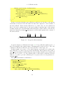
void timer init(void){
timer disabletimer() ;
T0RH = 0x00;
T0RL = 0x00;
T0H = 0x00;
T0L = 0x01;
1
2
3
4
5
6
1
Strange enough, that is not documented in [6]
13
3. Timer module
T0CTL0 = 0x00;
T0CTL1 = 0x11;
SET VECTOR(TIMER0, timer interrupt);
IRQ0ENL |= 0x20;
IRQ0ENH |= 0x20;
rounds = 0;
timer enabletimer();
7
8
9
10
11
12
13
14
}
where rounds has been defined with unsigned int rounds; as a global variable.
In line 2, the timer is disabled to avoid interrupts during initialization. In lines
3 and 4, the reload value is set to 0x0000 (note that the high byte is written
first!) and in lines 5–6 the counter value is set to 0x0001. Lines 7 and 8 configure
the timer to be in continuous mode, enable the interrupt at reaching the reload
value and set a prescale of 4 (the prescale value is somewhat arbitrary but this a
reasonable compromise between high accuracy and long wrap-around time of the
32-bit-counter). Lines 9 to 11 set and enable the interrupt routine for the timer:
each time the counter reaches the reload value, timer interrupt is called. Line
12 resets the rounds-variable which counts the number of interrupts and in line 13,
the timer is enabled to start counting.
The interrupt routine just has to increment the rounds-variable and therefore
simply is:
void interrupt timer interrupt(void){
++rounds;
}
Note that if rounds is 0xFFFF, incrementation leads to 0x0000.
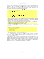
Now, it is possible to define the routine timer gettickcount which returns a
32-bit-value representing the total number of clock ticks so far:
1
2
3
4
5
6
unsigned long timer gettickcount(void){
unsigned long result;
result = ((unsigned int)T0H << 8) | T0L;
result += (unsigned long)rounds*65536;
return result;
}
T is calculated via the formula derived above: rounds * 65536 + counter. In
line 4, rounds is converted to a 32-bit-value in order to fit the result of the multiplication. If this is omitted, only the least significant byte of the result is stored
(for the same reason, T0H is converted to a 16-bit-value before shifting in line 3).
As stated in section B.2, it is important first to read the high byte and then the
low byte of the timer counter which is done in line 3.
If calculated as described above, T will reach a maximum value of 0xFFFFFFFF
(if both rounds and the timer counter have the value 0xFFFF). The next value will
be 0 as both rounds and the timer counter are zero after incrementing.
14
3. Timer module
Note that all functions work on clock ticks and not on actual time passed. To
convert clock ticks to microseconds, one has (given the prescale value of 4 and the
System clock of 5.5296MHz) to multiply by 0.7234. As floating point arithmetics
uses much time and much (code) space, it is easier to code this fixed multiplication “by hand” by using addition and multiplication. In order to do that, express
the value to be multiplied by, as binary number: (0.723)10 = (0.1011100100)2 (to
conserve accuracy of a 3-digit decimal value, one should compute 10 binary digits).
Multiplying by (0.1)2 is the same as bit-shifting the value to the right by one; multiplying by (0.01)2 is the same as right-shifting by two and so on. Keeping that in
mind, one just has to add up the bits:
#define TIMER TICKS TO MICRO(a) (((a) >> 1) + ((a) >> 3) + \
((a)>>4) + ((a)>>5) + ((a)>>8))
#define TIMER MICROS TO TICKS(a) ((a) + ((a)>>2) + ((a)>>3) + ((a)
>>7))
The second macro is the other way round: it converts microseconds to a T -value.
Those macros are defined in timer.h and can be used in other modules.
3.2.1. Disabled interrupts
Incrementation of rounds is done via an interrupt routine. Therefore, if interrupts
are globally disabled, rounds is not incremented and measuring time intervals by
calling timer gettickcount can lead to wrong results.
There are three possible workarounds for that:
1. Do not measure time intervals with interrupts disabled (in particular not
within interrupts).
2. In timer gettickcount, a small piece of code can be added which checks
whether an interrupt is pending and increment rounds if necessary.
3. Do not disable all interrupts: If processing interrupts, for example, enable the
processing of the timer0 interrupt.
Note that 1. does not prevent another problem: if interrupts are globally disabled
for a longer period of time (longer than the duration of one round), an interrupt
can get lost (as the timer elapses twice during that period of time, but only one
interrupt is processed) which leads to wrong counting and wrong results even if the
timer module is not used in that particular interrupt routine.
Workaround 2. only works if timer gettickcount is called with a time period
shorter than one full timer round. Therefore, this is only a solution for some special cases. This was implemented by inserting following code at the beginning of
timer gettickcount:
15
3. Timer module
1
2
3
4
if (IRQ0 & 0x20){
++rounds;
asm(”ANDX %FC0,#%DF”);
}
In line 1, it is checked whether an interrupt for timer0 is pending. If this is the
case, rounds is incremented (just as it would have been if processing the interrupt
directly) and the interrupt-pending flag is cleared to prevent another incrementation
because of the same interrupt.
Considering the limitations of the other workarounds, only 3. can be called a
solution and that is the preferred way to deal with this problem. Therefore, if an
interrupt is entered, it should re-enable the timer interrupt (no matter whether it
uses the timer or not). This step can only be skipped if the interrupt routine has a
maximal runtime that does not exceed the duration of one full timer round.
3.2.2. Race conditions
There is still another problem to address: During reading the timer counter and
rounds to calculate T in timer gettickcount, the timer interrupt could be fired.
That can lead to problems if the timer counter has a value c close to its maximal
value (0xFFFF) whereas rounds has some arbitrary value r: If first c is read, then
an interrupt is fired (where r is incremented) and then the (incremented) rounds
variable is read, it results in r + 1 and the result is wrong by about 65536 ticks.
This should be prevented.
A first idea might be to disable interrupts for the time T is calculated:
1
2
3
4
5
6
7
8
unsigned long timer gettickcount(void){
unsigned long result;
DI();
result = ((unsigned int)T0H << 8) | T0L;
result += (unsigned long)rounds*65536;
EI();
return result;
}
But that doesn’t solve the problem: if the timer counter wraps around between
lines 3 and 4, rounds is not incremented and in line 5, the wrong value is used.
A refinement of this solution could be to test after line 5, whether a timer interrupt would have occured in the meantime (by checking the corresponding interrupt
pending flag) and correct the result by adding 65536. However, this is not a good
solution as the timer might have elapsed just after line 5 (thus, result would have
a correct value to which is added 65536, making it totally wrong. . . ).
A better solution for this problem is to disable interrupts at the beginning of the
routine, calculate T and check whether an interrupt would have been fired in the
meantime (by testing whether the corresponding bit is set in IRQx). If this is the
16
3. Timer module
case, rounds is incremented, the interrupt-pending bit is cleared and the calculation
of T is repeated:
1
2
3
4
5
6
7
8
9
10
11
12
13
14
15
16
17
18
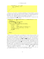
unsigned long timer gettickcount(void){
unsigned long result;
unsigned char irqctl save = IRQCTL;
DI();
while(true){
result = ((unsigned int)T0H << 8) | T0L;
result |= (unsigned long)rounds << 16;
if (IRQ0 & 0x20){
++rounds;
//clear the flag (IRQ0 is at address %FC0)
asm(”ANDX %FC0,#%DF”);
}
else{
IRQCTL = irqctl save;
return result;
}
}
}
In line 4, interrupts are globally disabled. In line 6 and 7, T is calculated just as
before (multiplying by 65536 is the same as shifting to the left by 16 bits). In line
8, the interrupt-pending-bit is tested and if it was set, rounds is incremented and
the interrupt-pending-bit is cleared (to avoid double incrementation of rounds). If
it was not set, no interrupt has occured in the meantime and rounds and the timer
counter had consistent values during calculation, and the result can be returned.
As it would be undesireable to change the status of whether interrupts are disabled
or enabled after executing the function, interrupts are not enabled at the end of
the function via EI() but rather the original state (as saved at the beginning of the
function in line 3) is restored just before exiting the function in line 14.
3.2.3. Timer counter behaviour
As mentioned in section B.1, it is not clear from the documentation how long the
timer counter has value 0, if the reload value is set to 0: either the interrupt is
fired immediately if the counter reaches 0 (by wrapping around from 0xFFFF) or
it remains 0 for P S system clock periods. The latter can result in wrong return
values from timer gettickcount: if the timer counter is 0 at when it is read, no
interrupt is fired and the value of rounds is too small, giving a wrong result.
But if prescale values are small, an interrupt will be fired between reading the
counter value in line 6 and checking the interrupt status in line 8. “Small” means
that the prescale value must be less than the execution time of line 7. As the
prescale value is only 4 and line 7 needs at least two 8-bit-moving instructions of
17
3. Timer module
which each takes at least 3 System clocks2 , that is guaranteed in this case but the
problem should be kept in mind when changing the prescale value or when changing
the code checking for interrupts.
3.3. Summary
It can be seen that even a problem as simple as measuring time with a timer is
not trivial to implement at all: Due to documentation bugs, a lot of testing was
needed and a good solution — which is time efficient, space efficient and simple —
for the race condition between the timer interrupt, timer incrementation (which is
independent from code execution) and timer gettickcount had to be found.
The timer could be further improved by rewriting the (presumably often used)
function timer gettickcount in assembly as bit-shifting by multiples of 8 is poorly
optimized in the compiler. This is done as an example of code optimizations in
section E.
2
an analysis of the assembler file shows that line 7 is encoded very unefficiently with an loop
executed 16 times, each doing four additions of which each takes 3 cycles so line 7 takes a more
than 192 System clock cycles
18
4. Callback module
Many microprocessor programming problems involve different tasks (or modules)
which should be run at parallel. In this project, the following parts have to be
executed regularly:
Keyboard module: This module has to watch the pins connected to the keyboard continuously.
Display module: even is the value to display is unchanged, the display has to
be update its output frequently (see section 5.1 for details).
Heater module: has to set a output pin alternatingly to high and (after some
specific time determined by the current heater level) to low.
User interface: Once a key is pressed, the display might need an update (if
the user wants to display other data, for example)
Failure checking: The microprocessor should check frequently whether an
internal failure condition applies and switch off the system for safety
Controller module: reading measured temperature, calculation and setting a
new heater level.
All this tasks have to be executed “simultaneously”. Of course, as having only one
processor true simultaneity is not possible. Rather, the tasks have to be executed
one after another in a fast sequence. In the main program, an infinite loop could
therefore call one module after another, the modules would have to make sure that
the time they need to perform their task is small so that no module has to wait for
a long time. However, the response time of the keyboard module (the time between
two calls of the keyboard routine) has to lie under about 30 s (see section 6.1) not
to loose any data. Therefore, at least for the keyboard, the invocation has to be
done via interrupt to ensure such short response times.
The heater module would have to be called frequently enough to let it check
whether to update the output port (it should be called more often than 100 times
per second).
Some modules take much more time than others: reading the temperature alone
can take about 1ms (depending on the implementation). On the other hand, some
tasks are very fast and do not need to be called very often (such as the display
µ
19
4. Callback module
update) and some tasks (like the heater output module) just have to wait for a
certain time (which is relatively long) to perform the next action.
Those are the issues the callback module tries to address: it allows for modules
to register a callback function of that module that is then called either regularly
at a certain frequency or only once after a defined amount of time. This idea of
executing different functions one after another in a fast sequence is similar to a
scheduler in multi-tasking operating system, which executes all running tasks in
turn, according to their priority setting. However, there is one major difference: in
our case, just certain functions are called regularly (which should return as fast as
possible) whereas within an multi-tasking operating system, processes are actively
interrupted during execution, their state saved and another process is executed.
4.1. Usage
As already mentioned, the callback module should allow other modules to register
certain functions. To do that, a function callback add is introduced which has the
function head
unsigned char callback add(unsigned char mode, unsigned long micros, cfptr
callback);
The first parameter is either CALLBACK MODE CONTINUOUS if the callback function
should be called continuously or CALLBACK MODE ONCE if the callback function should
be called only once. The second parameter gives the timeout in microseconds (which
is the calling period in the continuous mode). The third parameter is a pointer to
the function to be called back. The type cfptr (abbrevation for “callback function
pointer”) is defined via
typedef void(*cfptr)(void);
that is, a pointer to a function with no arguments which does not return anything.
The return value of this function is a handle for the callback which can be used
with other functions to identify an installed callback. In this case, there is only one
function which makes use of that:
void callback delete (unsigned char handle);
which deletes the callback identified by the parameter handle.
As in all modules, there is an initialization function called callback init with
no parameters and no return value.
4.2. Implementation
After having discussed the outer view of the module — i.e. the functions and their
meaning — I will describe the internal module details in this section.
20
4. Callback module
The overall idea of implementation the described behaviour is that — for each
registered callback — the deadline is calculated and stored as a tickcount value
(see section 3 for meaning of this value). Then, the current tickcount is compared
regularly to the stored deadlines and if a deadline has elapsed, the callback function
is called and (if the callback is in continuous mode) the deadline is updated.
The comparison between the current tickcount value and the stored deadlines
is done in a routine callback poll which has to be called regularly in the main
loop (see section 11).
As the module has to keep track of all currently registered callbacks, their associated operation modes, callback function addresses, calling periods and deadlines,
the following four arrays are defined:
1
2
3
4
unsigned long deadlines[CALLBACK N];
unsigned long periods[CALLBACK N];
unsigned char modes[CALLBACK N];
cfptr callbacks [CALLBACK N];
where CALLBACK N is defined in callback.h and is 4 in our case. It should be set to a
low value which still allows to accomodate all callbacks ever needed simulatonuously
in the program.
A specific callback is identified by a number between 0 an CALLBACK N-1. This
number is used as an index to the arrays, which contain the information for this
callback. Therefore, this index can be used as the handle as explained in section
4.1.
A callback to be disabled (or an index currently not being used) can be implemented as an additional mode CALLBACK MODE DISABLED. So the callback deletefunction is just
void callback delete (unsigned char handle){
modes[handle] = CALLBACK MODE DISABLED;
}
The most important function in this module is the callback poll function which
calls the callback functions of the callbacks whose deadline has elapsed. As the
function is to be called in a fast sequence and most of the time no deadline will have
elapsed, a time efficient implementation should ensure that this function returns
very fast if no deadline has elapsed. To do that, a global variable next is introduced
which is the handle of the callback to be called next. Of course, next has to be
updated each time a callback function is called or a callback is added (how the
case of deletion is handled is discussed below). next has the special value 0xFF if
currently no callback is enabled. The updating of next is done in a function called
callback updatenext which will be discussed later.
A first version of the callback poll function could then be like this:
1
2
void callback poll (void){
if (next!=0xFF){
21
4. Callback module
if (timer gettickcount()>deadlines[next]){
callbacks [next]() ;
if (modes[next]==CALLBACK MODE ONCE)
modes[next] = CALLBACK MODE DISABLED;
else if (modes[next]==CALLBACK MODE CONTINUOUS)
deadlines [next] += periods[next];
callback updatenext();
}
3
4
5
6
7
8
9
10
}
11
12
}
In line 2 is checked whether any callback is enabled at all. In line 3, the current
tickcount is retrieved from the timer module and compared to the deadline of
the next callback. If the current callback is to be called only once it is disabled in
line 6, if it is in continuous mode, the new deadline is just the sum of the current
deadline and the period in which this callback should be called. In line 9, the already
mentioned function callback updatenext is called which updates the contents of
the next variable.
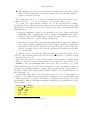
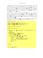
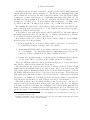
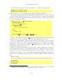
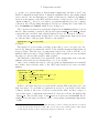
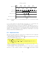
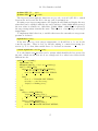
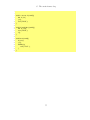
0 1 2
T = 0 now
0
d0 d1 d2
3
d3
T
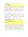
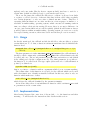
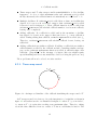
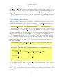
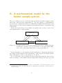
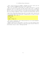
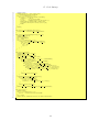
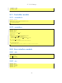
Figure 4.1.: A typical callback timeline.
A typical situation is illustrated in figure 4.1: Four callbacks, numbered 0 to 3
have been installed, the current values of deadlines[i] is denoted by di . The only
continuous callback is callback 0, all others should be called only once.
In this example, it is easy to follow what happens: next will be 0 as this is the
next callback to be called. As long as the current tickcount T (that is, the result of
timer gettickcount) is smaller than the next deadline (which is d0 ), nothing will
happen. As soon as T > d0 , the callback will be called and d0 will have the new
value d0 + p0 where p0 is the callback-period as given as the second parameter to
callback add.
The updatenext-function will then be
1
2
3
4
5
6
7
8
void callback updatenext(){
unsigned long min,now;
unsigned short i;
now = timer gettickcount();
min = 0xFFFFFFFF;
next = 0xFF;
for(i=0; i<CALLBACK N; ++i){
if (modes[i]!=CALLBACK MODE DISABLED){
22
4. Callback module
if (deadlines [ i ] − now < min){
min = deadlines[i] − now;
next = i;
}
9
10
11
12
}
13
}
14
15
}
In the for-loop from line 7 onwards, the minimum of the time difference between
now (which is the current tickcount T ) and the deadlines of all enabled callbacks is
determined. After running this method, next indicates the callback which is to be
called next. If no callback is enabled, next is 0xFF as it should be.
Now, only the callback add function is left. Its main task is to transfer the data
from its parameters to the four arrays:
1
2
3
4
5
6
7
8
9
10
11
12
13
14
15
unsigned char callback add(unsigned char mode, unsigned long micros, cfptr
callback){
unsigned char j;
j = CALLBACK INVALID HANDLE;
for(j=0; j<CALLBACK N; ++j){
if (modes[j]==CALLBACK MODE DISABLED){
callbacks [ j ] = callback;
modes[j]
= mode;
periods[ j ] = TIMER MICROS TO TICKS(micros);
deadlines [ j ] = timer gettickcount() + periods[j ];
callback updatenext();
break;
}
}
return j;
}
In the for-loop starting in line 4, an unused slot in the arrays is searched. If
one is found (that is, a disabled callback is found), it is used and all data given in
the parameters is transferred. As mentioned in section 3.2, microseconds can be
converted to timer ticks using the TIMER MICORS TO TICKS-macro. The deadline of
this callback, i.e. the tickcount-value when the callback function should be called
first is obviously the current tickcount plus the desired timeout (in ticks). As a new
callback has been installed, callback updatenext should be called which is done in
line 10. As an empty slot was found, the for-loop can be exited in line 11. In line 14,
the current value of j is just the index used for the callback data, i.e. j is what was
called the handle of the callback before which is returned. If no unused callback-slot
can be found, the function returns the value of CALLBACK INVALID HANDLE which
is defined to be 0xFF in callback.h.
The implementation so far was easy and straight-forward. However, there are
some situations where the code does not work as desired, namely:
23
4. Callback module
Timer wrap-round: T value wraps round from 0xFFFFFFFF to 0. If a deadline
happens to be close to that maximum value and callback poll is called
shortly afterwards, the callback function is mistakenly not called as T < di .
Multiple deadlines: If callback poll is called if more than one deadline has
elapsed, it does not work as desired: suppose that callback poll is called
between d1 and d2 in figure 4.1. Then, callback function 0 will be called but
callback updatenext will schedule callback number 2 as its next callback,
leaving out 1 completely.
Adding callbacks:
If a callback is added and in the meantime a deadline
has elapsed, it doesn’t work: suppose that just before d0 , a new callback is
added. During adding that callback, callback updatenext is called after d0 .
Therefore, callback updatenext will schedule callback 1 next, leaving out
callback 0.
Adding callbacks from within a callback: If adding a callback from within a
callback function called by the callback module, something similar can happen: as the callback updatenext function is called, it effectivly skips other
callbacks. (Depending on the attempt of solution, this case might require
special handling and is not automatically solved by solving the previous one.)
Those problems will now be solved one after another.
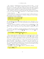
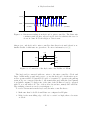
4.2.1. Timer wrap-round
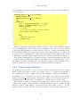
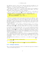
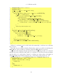
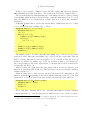
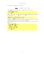
T =0
now
da
db
dc
dd
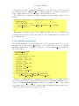
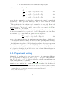
Figure 4.2.: An improved timeline of the callback visualizing the wrap-round of T
As T wraps around, it is better to drop the imagination of a timeline as drawn in
figure 4.1 and rather use the one illustrated in figure 4.2 where T “goes in circles”,
i.e. starts at T = 0 again after reaching some maximum value. Therefore, asking
about the time difference from two values of T has no well-defined solution: The
24
4. Callback module
time difference between dc and dd can be either the dashed line (in which case dd is
assumed to be in the relative future of dc ) or all the way from dd over T = 0 to dc
(in this case, dc would be in the relative future of dd ).
The discussion also shows how to solve the problem: with the a-priori assumption
which of the two T -values to be compared lies in the relative future of the other,
the distance in time between the two can be calculated.
This is done in the method timer getdiff which takes two 32-bit-values as
arguments of which the first is assumed to lie in the relative future of the second:
1
2
3
4
unsigned long timer getdiff(unsigned long future, unsigned long past){
if (future >= past) return (future − past);
else return (0xFFFFFFFF − past) + future + 1;
}
If T has not wrapped around between past and future, the difference of the
T values is returned (line 2), else the T has wrapped around and the time difference between the parameters is calculated by adding the time before wrap-around,
0xFFFFFFFF - past to the time since wrap-around, future. As T wraps around
from the maximum value 0xFFFFFFFF to 0, the function should return one more
than just mentioned.
The problem was to decide whether a deadline has elapsed or not at the beginning of callback poll. The following observation is helpful: If we assume
that deadlines[next] is in the future (what will be the case most of the times),
we should get an ever decreasing value. As soon as the deadline has elpased,
the value becomes suddenly very large. By restricting the allowed values of the
timeout for callback add it can always be assured that the difference between
deadlines[next] and now is normally under 0x7FFFFFFF. If the deadline elapses,
this difference will become some value near to 0xFFFFFFFF and start decreasing but
remain over 0x7FFFFFFF for a long time.
So a deadlines[next] has elapsed iff the difference is bigger than 0x7FFFFFFF.
That restricts the possible values for the timeout to 0–0x7FFFFFFF ticks or about
1553489000 s. That is a bit more than 25 minutes and enough for almost all
applications.
To implement the modification, one line has to be modified in callback poll:
The line
µ
3
if (timer gettickcount()>deadlines[next]){
is to be replaced by
3
if ( timer getdiff (deadlines [next ], timer gettickcount())>0x7FFFFFFF){
4.2.2. Multiple deadlines
The second problem was that if more than one deadline has elapsed, the calculation
of the next callback skips all those.
25
4. Callback module
The solution is to base the calculation of the next callback not on the real time
but on the value of deadlines[next], i.e. the relative time of the different deadlines. To make it easier to speak, I define deadlines[next] to be virtual now (if the
deadline has elapsed) and real now the most recent value of timer gettickcount.
All considerations for which only the relative values of the deadlines are important (as deciding which callback is next) should use the virtual now, whereas all
considerations for which the real time is important, should use real now.
After applying the changes, callback poll is:
1
2
3
4
5
6
7
8
9
10
11
12
13
14
15
void callback poll (void){
unsigned long virt now, real now;
real now = timer gettickcount();
if (next!=0xFF){
if ( timer getdiff (deadlines [next ], real now)>0x7FFFFFFF){
virt now = deadlines[next ];
callbacks [next]() ;
if (modes[next]==CALLBACK MODE ONCE)
modes[next] = CALLBACK MODE DISABLED;
else if (modes[next]==CALLBACK MODE CONTINUOUS)
deadlines [next] += periods[next];
callback updatenext(virt now);
}
}
}
The changes made affect lines 2, where the two newly introduced variables are
declared; 3 and 6 where they are assigned their value as defined before and line 12,
where code updatenext has now one parameter: the tickcount it should base its
decision for determine the next callback on.
callback updatenext has only minor changes: instead of declaring and assigning
now as a local variable, it is used as parameter. Everything else remains unchanged.
4.2.3. Adding callbacks
If adding a callback, callback updatenext must not be called directly. With the
terms from the last section, the problem can be formulated simply: we don’t know
the virtual now that has to be passed as parameter to callback updatenext.
Therefore, callback add only makes a new entry in the arrays but does not
call callback updatenext directly. Instead, it calls callback poll which can
first determine whether a deadline has elapsed before considering the newly added
callback in the calculation of next. callback poll has to be modified to call
callback updatenext every time to ensure that a newly added callback is taken
into consideration soon (it could be next. . . ). In that case, virtual now would have
the same value as real now if no deadline has elapsed.
26
4. Callback module
µ
If applying those changes, another problem arises: if the timeout of the added
callback is very small — say 1 s, its deadline as set in callback add will be “now
+ 1 s”. If then callback poll is called it calls timer gettickcount again to determine the virtual now which is used to determine next (assuming no deadline has
elapsed). But the time it takes from retrieving now in callback add to retrieving
virtual now in callback poll is more than that so the callback just added is not
called immediately as it should be.
The solution is to add the callback in callback add but not to calculate its
deadline. That is then done in callback poll. To let callback poll know for
which callbacks this should be done, the highest bit in the modes-array is set by
callback add and cleared by callback poll if done. To speed things up, a status
flag is set by callback add to indicate that a new callback is to be added which is
checked by callback poll.
The resulting code for callback add and callback poll and the status flag
handling (for more information about status flags see section F) is then
µ
1
unsigned char status;
2
3
4
5
#define STATUS FLAG SET(flag) (status |= flag)
#define STATUS FLAG CLEAR(flag) (status &= ˜(flag))
#define STATUS FLAG(flag) (status & (flag))
6
7
#define SF NEW CALLBACKS 0x01
8
9
#define MODE NEW 0x80
10
11
12
13
14
15
16
17
18
19
20
21
22
23
24
25
26
unsigned char callback add(unsigned char mode, unsigned long micros, cfptr
callback){
unsigned char j;
unsigned long now = timer gettickcount();
j = CALLBACK INVALID HANDLE;
for(j=0; j<CALLBACK N; ++j){
if (modes[j]==CALLBACK MODE DISABLED){
callbacks [ j ] = callback;
modes[j]
= mode | MODE NEW;
periods[ j ] = TIMER MICROS TO TICKS(micros);
STATUS FLAG SET(SF NEW CALLBACKS);
callback poll () ;
break;
}
}
return j;
}
27
28
void callback poll (void){
27
4. Callback module
unsigned long real now, virt now;
unsigned char i;
virt now = real now = timer gettickcount();
if (next!=0xFF){
if ( timer getdiff (deadlines [next ], real now) > 0x7FFFFFFF){
virt now = deadlines[next ];
if (modes[next]!=CALLBACK MODE DISABLED){
callbacks [next]() ;
if (modes[next]==CALLBACK MODE ONCE)
modes[next] = CALLBACK MODE DISABLED;
else if (modes[next]==CALLBACK MODE CONTINUOUS){
deadlines [next] = timer getsum(deadlines[next], periods[next]) ;
}
}
callback updatenext(virt now);
}
}
if (STATUS FLAG(SF NEW CALLBACKS)){
for(i=0; i<CALLBACK N; ++i){
if (modes[i] & MODE NEW){
modes[i] &= ˜MODE NEW;
deadlines [ i ] = timer getsum(virt now, periods[i]) ;
}
}
callback updatenext(virt now);
STATUS FLAG CLEAR(SF NEW CALLBACKS);
}
29
30
31
32
33
34
35
36
37
38
39
40
41
42
43
44
45
46
47
48
49
50
51
52
53
54
55
56
}
In line 21, callback poll is called after the status flag to indicate new callbacks
has been set.
From line 46, it is checked which callbacks have just been added by checking the
MODE NEW bit. The deadline is calculated and the MODE NEW bit is cleared.
Apart from the changes already described before the listing, in line 35 is checked
whether the next callback is still valid: it could have been deleted in the meantime
and should not be called then. Instead of adding two timer values, the function
timer getsum is used which can take care of the wrap-round behaviour of T :
1
2
3
4
5
6
7
8
unsigned long timer getsum(unsigned long time1, unsigned long time2){
unsigned long sum = time1 + time2;
if (sum > time1 && sum > time2){
return sum;
}
else{
return sum + 1;
}
28
4. Callback module
9
}
In line 2, the normal sum is calculated. If it is bigger than both the two parameters, no overflow has occured while adding. Otherwise, an overflow has occured
and 1 has to be added due to the wrap-around-behaviour of T .
4.2.4. Adding callbacks from within a callback
If adding callbacks from within a callback, callback poll is called twice: it is
active anyway because of the currently elapsed deadline and is called again by
callback add. This is unnecessary and can lead to undesired behaviour, especially
if static frames are used where all local variables of callback poll are at a fixed
memory location (for a more detailed description of static frames, see section C).
To prevent callback poll getting called twice, another flag is introduced which
indicates whether callback poll is currently active. Only if it is not active,
callback add calls callback poll. Define the new flag by
#define SF IN POLL
0x02
Insert the first line of the following listing at the very beginning of callback poll
and the second at the end:
1
2
STATUS FLAG SET(SF IN POLL);
STATUS FLAG CLEAR(SF IN POLL);
and in the last (large) listing, replace line 21 with
if (! STATUS FLAG(SF IN POLL))callback poll();
4.2.5. Callback behaviour after blocking
There is one more problem not mentioned before that can occur if the microprocessor is blocked for some time, for example by a callback function which has a
long runtime compared to the smallest period of a continuous callback installed. As
an example, let c be a continuous callback with a period of 1 s and d a callback
whose callback function has a running time of 10 s. If d is called, what will be the
behaviour of the callback module?
In the current implementation, d will get called as many times as it should have
been, i.e. about 10 times in the example. But the time between two consecutive
calls is very short, normally much shorter than the period set. In most applications,
this behaviour is not desired: a constant period between two calls is more important
than the number (or relative number) of callback calls (there might be exceptions,
of course), examples would be all continuous callbacks used in this project (there
are only two: the display callback and the controller callback).
Therefore, another change is applied: In callback poll, if callback i is called,
it is checked whether the next deadline of i lies in the (real) future. Normally, this
µ
29
µ
4. Callback module
should be the case. If not, the deadline is adjusted to lie periods[i] in the (real)
future:
else if (modes[next]==CALLBACK MODE CONTINUOUS){
deadlines [next] = timer getsum(deadlines[next], periods[next]) ;
if ( timer getdiff (deadlines [next ], real now) > periods[next]){
deadlines [next] = timer getsum(real now, periods[next]);
}
}
4.2.6. Module initialization
The module initialization has to reset all callbacks in marking them as unused.
Furthermore, next is set to 0xFF to indicate that no callback is currently active
and the two flags used in this module are cleared:
void callback init (){
unsigned char i;
for(i=0; i<CALLBACK N; ++i){
modes[i] = CALLBACK MODE DISABLED;
}
next = 0xFF;
STATUS FLAG CLEAR(SF IN POLL | SF NEW CALLBACKS);
}
30
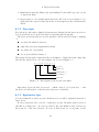
5. Display module
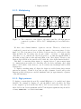
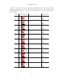
Four seven-segment digits are to be connected to the microcontroller to display
status information to enable the user to see what is currently happening in the
microcontroller.
5.1. Hardware
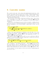
5.1.1. The seven-segment digits
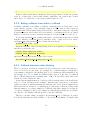
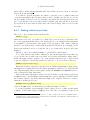
a
a
b
c
b
f
d
e
f
g
dp
g
e
c
d
dp
GND
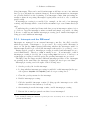
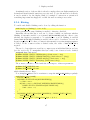
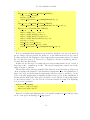
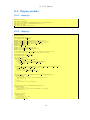
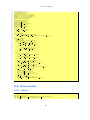
Figure 5.1.: Every digits consists of eight LEDs: seven composing a digit (labeled
a–g) and one for a decimal point (labeled dp).
As seen in figure 5.1, a seven-segment-display consists of eight LEDs that are
enabled if a current is flowing from an input pin (a–g and dp) to GND.
Therefore, the input pins can be connected to the output pins of the microcontroller, GND should then be connected to the same ground level as the MCU. To
prevent too high currents and damage of the LEDs, a resistor has to be used to limit
the maximum current to a reasonable value (which can be retrieved in the documentation of the seven-segment digits). For the digits used here, the data sheets give a
maximum current of 30 mA. The maximum allowed current for the microcontroller
output pins has also to be considered, up to 25mA are allowed according to [6].
3.3V
Therefore, the minimum value of the resistors should be R = UI = 25mA
= 132 .
Now, if an output pin is set to high, a current can flow from the output pin
through the resistor and the LED to GND and the LED will emit light.
W
31
5. Display module
5.1.2. Multiplexing
Z8 Encore! XP
PC0
PC1
PC2
PC3
PC4
PC5
PC6
PC7
PA3 PA2 PA1 PA0
a
a
a
b
c
b
f
d
e
f
g
dp
f
g
c
d
GND
b
f
d
e
g
e
a
a
b
c
dp
dp
f
g
c
d
GND
b
f
d
e
g
e
a
a
b
c
dp
dp
f
g
c
d
GND
b
f
d
e
g
e
a
b
c
dp
dp
g
e
c
d
dp
GND
Figure 5.2.: The connection of the digits to the microcontroller: All digit pins are
connected together to PC0 to PC7. Multiplexing is done with PA0 to
PA3.
We have only a limited number of pins we can use. Therefore, a little more
complicated connection is chosen to reduce the number of necessary pins to 12 (see
figure 5.2). The four pins at Port A (PA0 to PA3) are used to select which of the
digits should be lit: by setting only one pin of PAx — say PA0 – to high and the
other three to low, current can only flow from PC to ground through the LEDs of
the leftmost digit (but not through any LEDs of the other digits). Therefore, the
leftmost digit will show the pattern at PC while the other digits remain disabled.
This kind of connecting many input (or output) devices to just as many input
(or output) pins as necessary for connecting only one device and using other ouput
pins to select which of the devices to use is a widely used technique and is called
multiplexing.
To display something using all digits, the digits are enabled using their current
pattern in sequence. If this is done fast enough, a human observer will get the
impression that all digits are enabled simultaneously (at approximately a quarter
of the full intensity).
5.1.3. Digit patterns
To display a certain digit (from 0–F), certain LEDs have to be enabled and others
disabled. For example, to display a 1, only the LEDs b and c should be lit. That
is, the output for port C (if the bits PC0 to PC7 are seen as bits of the byte PC,
where PC0 is the lowest significant and PC7 the highest significant bit) should be
a binary 00000110b or a hexadecimal 0x06.
32
5. Display module
In the following table, the output bits for the input pins of the digits and the
resulting output byte for PC for all hexadecimal digits from 0–F are listed. It is
assumed that the digits are connected as shown in figure 5.2. The decimal point is
never enabled.
Digit
Desired pattern a
b
c
d
e
f
g
resulting PC
1
1
1 1
1
1 0
0x3F
0
1
1 0
0
0 0
0x06
1
1
0 1
1
0 1
0x5B
1
1
1 1
0
0 1
0x4F
0
1
1 0
0
1 1
0x66
1
0
1 1
0
1 1
0x6D
1
0
1 1
1
1 1
0x7D
1
1
1 0
0
0 0
0x07
1
1
1 1
1
1 1
0x7F
1
1
1 1
0
1 1
0x6F
A
1
(continued on next page)
1
1 0
1
1 1
0x77
a
b
f
g
e
c
d
0
a
b
f
g
e
c
d
1
a
b
f
g
e
c
d
2
a
b
f
g
e
c
d
3
a
b
f
g
e
c
d
4
a
b
f
g
e
c
d
5
a
b
f
g
e
c
d
6
a
b
f
g
e
c
d
7
a
b
f
g
e
c
d
8
a
b
f
g
e
c
d
9
a
b
f
g
e
c
d
33
5. Display module
(continued from previous page)
a
b
f
g
e
c
d
B
0
0
1 1
1
1 1
0x7C
0
0
0 1
1
0 1
0x58
0
1
1 1
1
0 1
0x5E
1
0
0 1
1
1 1
0x79
1
0
0 0
1
1 1
0x71
a
b
f
g
e
c
d
C
a
b
f
g
e
c
d
D
a
b
f
g
e
c
d
E
a
b
f
g
e
F
c
d
5.2. Software
5.2.1. Digit updating
As mentioned earlier, the microcontroller has to select the different digits and output
their respective patterns in a fast sequence. The step done every time in this
sequence is what is called updating here.
The current output pattern for each digit has to be saved along with the number
of the last digit that was updated:
unsigned char current display[4];
unsigned char last updated digit;
The array current display contains the output for PC for that digit. Digits are
numbered from 0 to 3, while 0 denotes the leftmost and 3 the rightmost digit.
Now, a function display update can be defined which does the actual updating:
1
2
3
4
5
6
7
void display update(void){
if ( last updated digit <3)last updated digit++;
else last updated digit =0;
PAOUT &= 0xF0;
PAOUT |= 1 << last updated digit;
PCOUT = current display[last updated digit];
}
In lines 2–3, the previously defined variable last updated digit is set to the
number of the next digit. If display update is called several times, the variable
34
5. Display module
last updated digit will have values in the sequence 0,1,2,3,0,1,2,. . . In lines 4–5,
the selection of the right digit is done: after execution of those lines, exactly one of
the output ports PA0–PA3 is set to high (according to last updated digit), all
the others are set to low. In line 6, the currently set output pattern for this digit is
sent to PC.
If code display is called fast enough, the impression of a constantly lit display
is obtained.
5.2.2. Setting the display
Other modules should have the possibility to configure the display module to let it
display certain numeric values. Instead of writing to current display directly, a
new function is defined which allows much easier usage:
void display displaynumber dec(unsigned int number dec, unsigned char dp);
If this method is called, the number given in the first parameter is displayed as
a decimal number, i.e. if number dec is 6512, digit number 0 sould display 6, digit
number 1 should display 5 and so on. The second parameter gives the position of a
decimal point which can have the values 1 to 4 to indicate that it should be displayed
after digit 0 to 3. If the parameter dp is zero, no decimal point is displayed.
To implement the method, it is convenient to define an array which allows to
easily convert digits into output patterns: display number mask. Accessing the
array using index i gives the output pattern for PC which represents that digit. As
hexadecimal digits are allowed, 0 ≤ i ≤ 15. Using the patterns from section 5.1.3,
the array definition is
const unsigned char display number mask[16] = {0x3F, 0x06, 0x5B, 0x4F, 0x66,
0x6D, 0x7D, 0x07, 0x7F, 0x6F, 0x77, 0x7C, 0x58, 0x5E, 0x79, 0x71};
Now, display number dec is defined as follows:
1
2
3
4
5
6
7
8
9
10
void display displaynumber dec(unsigned int number dec, unsigned char dp){
unsigned char i;
for(i=3; i!=0xFF; −−i){
current display [ i ] = display number mask[number dec % 10];
number dec /= 10;
}
if (dp>0){
current display [dp−1] |= DISPLAY DP;
}
}
The for-loop from line 3 sets current display starting with digit number 3,
i.e. the rightmost digit down to digit 0. If i is decremented from 0, the result is
0xFF in which case the for-loop is terminated.
In line 4, the last digit to display is calculated, that is the remainder if dividing
number dec by 10. In line 5, the rest of what is to be displayed is calculated, that
35
5. Display module
is all but the last digit of number dec. In line 7–9, the bit for the decimal point is
set if dp was not zero. DISPLAY DP is a constant defined to be 0x80 in timer.h; it
is the output pattern for PC to display only the decimal point.
In a similar way, a function to display numbers in hexadecimal format can be
defined:
1
2
3
4
5
6
7
void display displaynumber hex(unsigned int number hex){
unsigned char i;
for(i=3; i!=0xFF; −−i){
current display [ i ] = display number mask[number hex & 0x0F];
number hex >>= 4;
}
}
This function is simpler as the one to display decimal values as no decimal point
is implemented and the modulo and division can be implemented in a shorter and
more efficient way.
5.2.3. Module initialization
The module initilization has to configure the all PC-pins and PA0 to PA3 as output pins and set the current display to a reasonable value (i.e. not to display
anything). Furthermore, it installs a callback to call the display update function
after every 4ms.
1
2
3
4
5
6
7
8
9
10
11
12
13
14
15
void display init (void){
unsigned char i;
for(i=0; i<4; ++i)
current display [ i ] = 0x00;
last updated digit = 0;
PCADDR = ALT FUNC;
PCCTL = 0x00;
PCADDR = DATA DIR;
PCCTL = 0x00;
PAADDR = ALT FUNC;
PACTL &= 0xF0;
PAADDR = DATA DIR;
PACTL &= 0xF0;
callback add(CALLBACK MODE CONTINUOUS,
DISPLAY UPDATE PERIOD, &display update);
}
In lines 6–9, all PC-pins are configured as general purpose output pins. In lines
10–13, the same is done for PA0–PA3. For the usage of callback add in line 14 see
section 4.1; DISPLAY UPDATE PERIOD is defined to be 4000 s, i.e. 4ms. That results
in a update period for all digits of 16ms giving an update frequency just above
50Hz below which flickering is getting noticeable.
µ
36
5. Display module
A minimal version of the module is already complete that can display numbers in
decimal and hexadecimal format in a very easy way. To give the user more feedback,
it can be useful to let the display blink, for example to attract more attention if
something important has happend or while the user is setting a new value.
5.2.4. Blinking
To enable and disable blinking can be done by calling the function
void display set blinking (boolean onoff) ;
If the parameter is true, blinking is enabled, otherwise, disabled.
Internally, the module has to save two booleans of which one indicates whether
blinking is currently enabled or not (named BSF BLINKING) and the other to save
whether the display is currently to be switched on or not if blinking is enabled
(named BSF BLINK ON). If blinking is enabled, the second boolean has to be set to its
negation regularly. To do that, a counter is incremented every time display update
is called. If the counter reaches a defined value, the value of BSF BLINK ON is
negated.
The two boolean values are saved in a compact way as individual bits in one byte
(see also section F). To manipulate this byte easily, a set of macros is also defined:
unsigned char blink status;
#define BLINK STATUS SETFLAG(flag) (blink status |= flag)
#define BLINK STATUS CLEARFLAG(flag) (blink status &= ˜(flag))
#define BLINK STATUS SWAPFLAG(flag) (blink status ˆ= flag)
#define BLINK STATUS FLAG(flag) (blink status & flag)
Those macros should be called with the following two values as parameter:
#define BSF BLINKING 0x01
#define BSF BLINK ON 0x02
which identify the two flags.
Now, display update can be rewritten to swap the BSF BLINK ON-flag regularly:
1
2
3
4
5
6
7
8
9
10
11
void display update(void){
PCOUT = 0x00;
if (BLINK STATUS FLAG(BSF BLINKING)){
++blink counter;
if (blink counter==DISPLAY BLINKING HALFPERIOD){
BLINK STATUS SWAPFLAG(BSF BLINK ON);
blink counter = 0;
}
}
if (! BLINK STATUS FLAG(BSF BLINKING) || BLINK STATUS FLAG(
BSF BLINK ON)){
last updated digit = (last updated digit + 1) & 3;
37
5. Display module
PAOUT &= 0xF0;
PAOUT |= 1 << last updated digit;
PCOUT = current display[last updated digit];
12
13
14
}
15
16
}
In lines 3–9, blink counter is incremented once per function call. Whenever it
reaches DISPLAY BLINKING HALFPERIOD, the flag BSF BLINK ON is swapped (i.e. its
value is negated) and the counter is reset. Lines 11–14 implement the functionality
of the previous version of this function to update the next digit. They are only
executed if either blinking is off or blinking is on and at the same time BSF BLINK ON
is set. Otherwise, the output on PC is 0 as set in line 2 and the display remains
disabled.
DISPLAY BLINKING HALFPERIOD is the half of the blinking period, measured in
units of DISPLAY UPDATE PERIOD and defined as
#define DISPLAY BLINKING HALFPERIOD 50
which results in a blinking period of 400ms.
The function display set blinking whose behaviour has been already described
is then implemented as
1
2
3
4
5
void display set blinking (boolean onoff){
if (onoff) BLINK STATUS SETFLAG(BSF BLINKING);
else BLINK STATUS CLEARFLAG(BSF BLINKING);
blink counter=0;
}
which just sets or clears the BSF BLINKING-flag according to the parameter and
resets the counter.
38
6. Keyboard module
6.1. Hardware description
The information in this section is mainly taken from [1] and [2].
The keyboard protocol was introduced by IBM in 1984 and has changed only
very little since then. Whereas the physical connectors have changed from 5-pinDIN to 6-pin Mini-DIN (often just referred to as “PS/2 connector”), the protocol
itself remained mainly unchanged. Later versions have some additional features but
they remain backward-compatible.
As any data connection, the keyboard-microcontroller connection can be divided
into conceptual “layers”: A “physical layer” specifies how the physical connection
is made, i.e. how a bit-stream is encoded by setting the wire to high or low in a
certain sequence with a certain timing.
The next layer, the “data layer” specifies how to interpret the raw bit-stream to
get logical byte data.
The third layer, here the “application layer”, the semantical interpretation of the
data is given, i.e. what the data just sent means.
The distinction drawn between and the name of the layers differ from source to
source1 .
6.1.1. Physical layer
+5V
Rp
A
Ro
1
0
OUT
B
IN
F
Figure 6.1.: Physical connection between two microcontrollers to use for communication.
1
this labelling and distinction is actually my own and I don’t even know whether this is treated
elsewhere using layers. But it helps to get things sorted. . .
39
6. Keyboard module
Sending data from one microcontroller to another can be done by using input and
output pins in the way outlined in figure 6.1. The IN-pin is a high-impedance pins
whose status can be read by the microcontroller software. The OUT-pin is either
connected to ground or in tri-state, i.e. a high-impedance-state with resistor Ro . In
the first case, the potential at F is the one of ground: 0V. In the latter case, F is
at (almost) +5V as Ro Rp . Rp has a typical value in the range of 1–10k , while
Rp will be some M .2 In this project, a value of Rp = 4.7k has been used.
By building the same in the other direction (introducing INA and OUTB ), the
data connection is in both directions, i.e. both A and B can send and receive data,
having one bidirectional data line.
It is possible to save pins and connect both INA and OUTA to the same physical
pin which can act in both roles. As data is to be sent in both directions, roles have
to be changed if data is sent in the other direction.
If A wants to send a bit of data to B, it can set OUT to high or low accordingly.
However, there are some problems:
W
W
W
1. In most applications, A does not always want to send data. So there has to
be a distinction between “sending” and “not sending”.
2. Just setting OUT high and low according to the data to be send is not enough,
as — for example — two high bits cannot be distinguished from only one. So
some sort of more sophisticated encoding or timing is needed.
3. If using only one physical wire for both directions of commnunication, a change
of roles of the pins to act either as IN or OUT pin has to be initiated.
There are different solutions to those problems; in this case, a second data line is
introduced to address all problems, the Clock line.3
The first and second point is solved by the clock line: if the clock line is high
(pulled up by the pull-up resistor), no data is sent. As soon as data is sent, the
keyboard produces a alternating signal on the Clock line with a frequency of about
10–17kHz. Whenever Data is low, a bit can be read from Data. Clock then gets
high again and at the next low state of Clock, the next bit of data can be read from
Data and so on. During Clock is high, the keyboard changes Data to represent the
next bit in the bit-stream to be sent. This process can be seen in figure 6.2.
The third point is solved by giving the microcontroller all control over data direction: if the data direction is from keyboard to the microcontroller, it configures
both Data and Clock as IN-pins, they will then both be high. If the microntroller
wants to send data, it configures Data as OUT-pin and sets it to low. The keyboard
checks the status of Data regularly and changes the roles of its pins accordingly. In
2
Actually, Ro is the resistance of a transistor but thinking of a very high resistor is just as good
to understand how it works
3
If written capitalized, “Clock” and “Data” refer to the respective physical wires (the words with
a small letter preserve their original meaning)
40
6. Keyboard module
1
Clock
0
Data
1
0
(no data)
0
1
1
0
0
1
0
1
0
1
1
(no data)
ca. 30–50µs
time
Figure 6.2.: Bit-stream sending from keyboard to microcontroller: The Data wire
contains actual bit data only as long Clock is low which is the case for
about 30–50 s. If Clock is high, no data is sent.
µ
this project, only keyboard to microcontroller data direction is used, therefore no
further details on this issue are given here. For more information, see [1].
Z8 Encore! XP
Keyboard
+5V
5V
Rp
PA6
Data
PA7
Clock
GND
O
Figure 6.3.: Connection of the keyboard to the Z8 Encore! XP r .
The keyboard is connected with two wires to the microcontroller: Clock and
Data. Additionally, ground and power to power the keyboard. As the microncontroller operates with 3.3V but the PS/2 protocol requires 5V operation, the pull-up
resistors Rp are connected directly to the transformer used with the development
board which outputs 5V. Only some of the pins of the Z8 Encore! can be operated
with 5V, not only with 3.3V. Two of those were chosen here, namely PA7 and PA6.
The resulting connection can be seen in figure 6.3.
To read a bit-stream from the keyboard, the microcontroller has to:
1. Make sure that both Clock and Data are configured as IN-pins.
2. Wait for the next falling edge of Clock, i.e. wait for a high, then a low state
on Clock.
41
6. Keyboard module
3. Immediately after the falling edge (and during Clock is still low), read one bit
of data from Data.
4. Repeat steps 2–3 for all subsequent data bits. If Clock does not change to low
again after the expected time (from the clock frequency), the bit-stream has
ended.
6.1.2. Data layer
How the keyboard sends a (finite) bit-stream was discussed in the previous section.
Now is described how logical byte-data is sent using this bit-stream.
The keyboard sends data in one-byte packets, each in an 11-bit frame consisting
of
one start bit which is always 0
eight data bits (least significant bit first)
one parity bit (odd parity)
one stop bit which is always 1
The parity bit has such a value that the total number of high bits in the eight data
bits and the parity bit is odd. An example can be seen in figure 6.4.
0 1 1 0 0 1 0 1 0 1 1
stop bit
parity bit
high nibble: 5
low nibble: 3
start bit
Figure 6.4.: Bit sequence sent for the byte 0x53.
After that, eleven bit have been read — which compose one logical byte — and
the keyboard will start to send the next data byte as available.
6.1.3. Application layer
Now it is defined how bytes are sent. In this section, it will be explained what those
bytes mean.
If a key is pressed, the scancode of that key is sent. In many (but by far not
all) this is a single byte. If a key is released, the byte 0xFA is sent, followed by
the scancode of the key released. If a key is held down for a long time, it has
42
6. Keyboard module
the same effect as pressing it at a certain rate, i.e. more scancodes are sent to the
microcontroller at that rate.
Other data than scancodes as a key is pressed, held down or released is only sent
as response to commands sent by the microcontroller — which is not done in this
project — or to indicate an error — what does hopefully not happen and this case
is ignored.
As the scancodes of the keys are not always one byte long, one would normally
have a table of all keycodes in the program and look up the byte sequence sent
from the keyboard to determine which key has been pressed. Such processing is not
very difficult but uses much code space (or — depending on the implementation —
RAM) which is not left very much in this project.
As only seven keys are needed anyway (see section 10), we do not need to decode
all keys. Instead, only those keys are used which have a scancode that consists of
only one byte and “decoding” is trivial.
For a list of scancodes, see section D.
6.2. Implementation
Timing is very important: if the time between the first falling edge and starting the
reading process is too long, data bits can be lost. Therefore, receiving data from
the keyboard is done in an interrupt routine while other interrupts are disabled for
that time. The interrupt is fired at a falling edge of Clock.
At initialization, both Clock (PA7) and Data (PA6) are configured as input pins
and an interrupt is installed for a falling edge of Clock:
1
2
3
4
5
6
7
8
9
10
11
12
13
void keyboard init(void){
PAADDR = ALT FUNC;
PACTL &= 0x3F;
PAADDR = DATA DIR;
PACTL |= 0xC0;
PAADDR = OUT CTL;
PACTL |= 0xC0;
SET VECTOR(PA7 IVECT, keyboard interrupt);
IRQSS &= 0x7F;
IRQES &= 0x7F;
IRQ1ENH |= 0x80;
IRQ1ENL |= 0x80;
}
In lines 2–7, PA7 and PA6 are configured as digital input pins. In lines 9–10, the
interrupt installed in line 8 is configured to be fired at a falling edge at PA7. Lines
11–12 set the highest interrupt priority for this interrupt.
Whenever an interrupt occurs, keyboard interrupt is called. This routine handles the application layer, i.e. the interpretation of the bytes.
43
6. Keyboard module
To read the status of the Clock and Data line, two macros are introduced:
#define clock() (PAIN & 0x80)
#define data() (PAIN & 0x40)
which evaluate to a boolean true iff the respective inputs are high.
As already stated, this module assumes that only keys with a one-byte scancode
are pressed and that the keyboard does only send bytes to indicate pressing and
releasing of keys. The interrupt routine saves the scancode of the last pressed key
in a global variable lastkey:
void interrupt keyboard interrupt(void){
unsigned char byte;
byte = keyboard getbyte();
if (byte==0xF0){
while(clock()){}
byte = keyboard getbyte();
}
else{
lastkey = byte;
}
asm(”ANDX %FC3,#%7F ; IRQ1 &= 0x7F”);
}
1
2
3
4
5
6
7
8
9
10
11
12
In line 3, the function keyboard getbyte is called which handles the physical
and data layer, i.e. it receives the bit-stream and returns the byte sent.
The byte is either 0xF0 to indicate that a key has been released or the (one-byte)
scancode of a pressed key. In the first case, the next byte is read (in line 6) which is
the scancode of the released key. keyboard getbyte has to be called after the first
falling edge of Clock, therefore in line 5, this falling edge is waited for by looping
doing nothing until Clock is low.
During receiving, many falling clock edges have ocurred causing the pending-bit
for this interrupt getting set again which would call it immediately after exiting.
As this is not desired, the interrupt pending bit is cleared in line 11. This is done in
assembler in according to the recommendation manipulating IRQ bytes given in [6]
to avoid loss of interrupts: it is not known how the C compiler compiles a statement
like
IRQ1 &= 0x7F;
For the C-Compiler, it would be absolutely valid to produce assembler like4
LD R0,IRQ1
AND R0,#%7F
LD IRQ1,R0
1
2
3
4
If you type and try to compile the example, it will not work, as I have omitted some specialities
of Z8 Encore! assembler that are not important to make the point here.
44
6. Keyboard module
In line 1, the contents of IRQ1 is loaded into the register R0, where an bit-wise
AND with 0x7F is calculated in line 2. The result is moved back to IRQ1 in line 3.5
The problem is that another interrupt can occur during execution of line 2, setting
a bit in IRQ1 which is then be deleted in line 3 and the interrupt is lost. To avoid
that, the AND has to be calculated in a single step as is done by the assembler
instruction.
keyboard getbyte has to receive the bit-stream as outlined in section 6.1.1, that
is, to read the bits after a falling edge of Clock:
unsigned char keyboard getbyte(){
unsigned char byte, i;
byte = 0;
for(i=0; i<8; ++i){
while(!clock()){} while(clock()){}
if (data()){
byte |= 1 << i;
}
}
while(!clock()){} while(clock()){}
while(!clock()){} while(clock()){}
return byte;
}
1
2
3
4
5
6
7
8
9
10
11
12
13
The function has to be called after the first falling edge of Clock as long as the
start bit is valid. After the next falling edge of the clock, the lowest value data bit
will be on Data, then the second lowest and so on. To read those bits, the for-loop
in lines 4–9 waits for a falling edge on Clock. If Data is high, a 1 is inserted at
the corresponding position into byte in line 7: the first bit received is inserted as
lowest value bit and so on.
After receiving the eight data bits, the parity and stop bits are waited for in
lines 10–11 but their value is ignored. The data byte is now saved in byte which is
returned in line 12.
Other modules have to have access to the key last pressed. For this purpose, the
function keyboard getlastkey is provided which retuns the scancode of the last
pressed key or 0 if no key has been pressed since the last call of the function:
unsigned int keyboard getlastkey(void){
unsigned int res = lastkey;
lastkey=0;
return res;
}
1
2
3
4
5
Most of the time, lastkey will be zero. After the interrupt is executed, lastkey
contains the scancode of the key last pressed which is reset to zero in line 3. Subse5
This move-to-register/manipulate/move-to-memory scheme is very commonly used in most architectures, including the x86 Desktop processor architecture
45
6. Keyboard module
quent calls to keyboard getlastkey will only return a non-zero value if a key has
been sent in the meantime.
Note that no special measures are taken to prevent a race condition that can
occur if an interrupt is fired between lines 2 and 3. In this case, the key is lost. As
the probability for that is very low and this only affects the user-interaction in very
rare occasions where an easy work-around is available (the user just has to press the
key again if he notices that it didn’t have the desired effect), that does not seems
necessary.
6.2.1. Making infinite loops finite
The code so far contains many statement like
while(clock()){}
which wait for Clock to get either low or high. If for some reason (e.g. hardware failure or wrongly implemented keyboard driver), this does not happen, that statement
is an infinite loop preventing other parts of the program to run. Such conditions
should be avoided as they could result in undesired behaviour (for example, if the
heater was switched on before going into the loop, it just stays on and could cause
damage).
Therefore, those (potentially) infinite loops should be made finite.
To do that, timer1 is used and configured to fire an interrupt after some timeout,
i.e. in one-shot mode with some reasonable reload value and initial counter value.6
In the interrupt routine of timer1 , a boolean variable timeout is set to true and all
loops are adapted to check this variable as well; the loop above then would read
while(clock() && !timeout){}
But as the reading of the keyboard data is done within an interrupt routine, where
interrupts are normally disabled, the timer1 interrupt would have to be enabled (and
only this interrupt) what would require saving all IRQxENH and IRQxENL bytes to
restore them later what takes time.
Instead, the timer interrupt routine is disabled but the corresponding pending-bit
in IRQx is read to check whether an interrupt has occured: this bit is set if the timer
has reached elapsed even if the timer interrupt is not enabled. Therefore, a macro
timeout is defined as follows:
#define timeout() (IRQ0 & 0x40)
as bit 6 in IRQ0 is the one indicating a pending interrupt for timer1 .
So at the beginning of the interrupt routine, timer1 is set to a timeout and starts
counting. If the timer elapses, IRQ0[6] is set and all loops waiting for the Clock
6
for more information on timers, see section 3.1. The one-shot mode is not explained there,
but this mode operates just as the continuous mode with the only difference that the timer is
switched off after the first interrupt.
46
6. Keyboard module
µ
signal are exited immediately. keyboard getbyte receives 11 bit with an interval
between two bits of about 100 s. Two bytes are received if a key has been released.
Therefore, a timeout of about 3ms seems appropriate. Setting the timeout and
enabling the timer is done in keyboard timer start:
1
2
3
4
5
6
7
8
void keyboard timer start(void){
keyboard timer disable();
T1RH = 0x10;
T1RL = 0;
T1L = T1H = 0x00;
asm(”ANDX %FC0,#%BF ; IRQ0 &= ˜0x40”);
keyboard timer enable();
}
The reload value of timer1 is set to 0x1000 in lines 3–4 (which results in a timeout
of about 2.96ms), the initial counter value is reset in line 5. As an timer-interrupt
could have ocurred before, the pending-bit is cleared in line 6.
The macros to enable and disable timer1 used in lines 2 and 7 are defined as
#define keyboard timer disable() T1CTL1 &= 0x7F
#define keyboard timer enable() T1CTL1 |= 0x80
At module initialization, the timer has to be initialized to work in one-shot mode,
prescale 4:
void keyboard timer init(void){
keyboard timer disable();
T1CTL0 = 0x00;
T1CTL1 = 0x10;
}
This function is called once from keyboard init.
Now, keyboard timer start has to be called once at the beginning of the interrupt routine. At the end of the interrupt, timer1 can be disabled again (see section
G.5.2 for the resulting code).
The solution does not address all potential hardware problems: if the keyboard
interrupt is fired with at a very high frequency, the microcontroller will only execute
the keyboard interrupt and nothing else which can lead to the same problems as the
infinte loops before. Such a condition could not even be handled by the Watchdog
timer (see section 11.1.1) but this is very unlikely to happen.
47
7. Temperature module
The hardware and the software module for measuring temperature are described
more detailed in [3] but for the sake of completeness, a brief description of this
module is included here.
7.1. Hardware description
If used together with a microprocessor, the output of the sensor circuit has to be
a voltage in an appropriate range which can be used as input to an analog-digitalconverter (ADC). This is a device which maps an input voltage in the range 0–Vr
linearly to the digital output range 0–2n − 1. Vr is called reference voltage, n is the
resolution of the ADC, in bits.
The sigma-delta-ADC used in this project is already built into the microcontroller
chip and has a resolution of 10 bits, its reference voltage can either be configured
via the software (1.0 or 2.0V) or applied from an external source to the reference
voltage pin.
The task of the temperature module is to read the ADC output and to convert
it to a temperature which can be used in further calculations in other modules.
7.2. Implementation
The initialization of the module is done in temp init:
1
2
3
4
5
6
7
8
9
10
11
void temp init(void){
PBADDR = 0x07;
PBCTL |= 0x21;
PBADDR = ALT FUNC;
PBCTL |= 0x21;
ADCCTL0 = 0x70;
ADCCTL1 = 0x80;
IRQ0ENH &= 0xFE;
IRQ0ENL &= 0xFE;
ADCCTL0 |= 0x80;
}
Lines 2–5 set the alternate function for PB0 to let it function as analog input
ANA0 and for PB6 to let it operate as reference voltage output Vref (rather than
48
7. Temperature module
to operate as a general purpose digital input/output pin). In lines 6 and 7, the
ADC is configured in single-ended, continuous, unbuffered mode; the alarms (which
can be used to fire an interrupt at certain conditions) are disabled and ANA0 is
selected as the input for the ADC and the reference voltage is set to 2.0V which is
output at PB6/Vref . As we do not want to get an interrupt fired at every complete
conversion, the corresponding interrupt is disabled by clearing the lowest value bit
in both IRQ0ENH and IRQ0ENL which is done in lines 8–9.
The conversion is started by setting the highest bit in ADCCTL0 which is done in
line 10. After starting conversion, the special registers ADCD H and ADCD L always
contain the last converted value which is updated every 256 system clock cycles.
In the end, the temperature module has to read a temperature that can be used
by other modules of the program. Therefore, the method
signed int temp gettemp(void);
is defined.
The method does not return a floating point value to save code space (see also
section E). Instead, it returns the tenfold of the actually measured temperature in
degrees celcius. That allows for a temperature range from −3276.8–3276.7 to be
handled with an accuracy of 0.1 which is more than enough in our case as neither
the range nor the resolution will be fully required.
The internals of this method are dependent on the temperature sensor and amplification used and are not discussed here; see [3] for details.
Just to have a functional version of the program, an implementation is included
here which only reads the value of the ADC and devides it by some resonable
number:
signed int temp gettemp(void){
signed int data raw;
data raw = ((unsigned int)ADCD H << 8);
data raw |= ADCD L & 0xE0;
//TODO: convert raw value to temperature!
return data raw / 20;
}
1
2
3
4
5
6
7
In line 3, the high data byte is read from the current ADC value (here also, the
high byte has to be read first as explained in section B.2 in detail for the timer
counter). In line 4, the lower 3 bits are read from the ADC. As they compose a
signed value in two-complement representation1 , they are read into the highest bits
of data raw. The absolute value of raw data is now between 0 and 0xEFE0. By dividing it by 20, the range is redued to 3070, corresponding a maximum temperature
of 307 .
1
Here, 11 bit are read. Normally, the value should be positive, reducing the effective resolution
to the 10 bit aleady mentioned. But offset errors can produce small negative values which
would appear as large positive values if the sign is not taken into account.
49
8. Heater module
This module — including the hardware — is explained much more detailed in [4].
It is only discussed very briefly here.
8.1. High power switching with triacs
The heater is a high-power device. When switching high powers with small currents
(as is the case here), a triac can be used. This is a device similar to a transistor
in that it has three pins, two terminals (terminal 1 and terminal 2) the gate and
allows to switch a current to flow from one terminal to another if a positive voltage
is applied at the gate.
If comparing a triac to a transistor, the main differences are
1. The currents that can be switched with a triac can be much higher than for
the transistor.
2. Current in a triac can flow in both directions, i.e. both from terminal 1 to
terminal 2 and vice versa.
3. The triac becomes conductive (between the terminals) if either the gate is
high or the current flowing from one terminal to the other is higher than
some triac specific holding current (which is typically low compared to the
current to be switched).
The first two point allow the triac to be used to switch high alternating currents
as used for the heater in our case. To do that, the gate is connected to an digital
output pin of the microcontroller. If it is set to high, the current is already enough
to make the triac conductive (if the right triac type is chosen).1
Point 3. means that if using a triac, current can only be switched off at a zerocrossing of the voltage.2 One might think that is too unflexible for many applications
1
In real applications, one would not connect the microcontroller output directly to the triac gate
but seperate the high voltage (heater) circuit from the low-voltage (microcontroller) circuit
electrically to avoid damage. Connection between the cicuits can be done optically with an
optocoupler.
2
There are some problems if switching inductive or capacitive loads as then current and voltage
are not in phase. Then the triac becomes non-conductive if the current has a zero-crossing
while the voltage switched off can still be high. That is undesirable for reasons which are
explained in the text. The heater can be assumed to be a purely resistive load, thus current
and voltage are always in phase and those problems are not important here.
50
8. Heater module
but indeed this behaviour is very desirable: if switching off (or on) at a point where
the voltage is high, fast change in the current will result, i.e. high frequency components in currents which should be avoided as this leads to emission of radiation and
to high frequency components in the whole power grid. As the power grid has to
meet specifications of frequency and voltage stability very closely, such disturbances
have to be avoided.3
For this reason, also switching current through the triac on should only be done
at zero-crossing of the voltage. That is, the gate should be only set to high if the
voltage has a zero-crossing. This is called zero-cross switching.
In this case, two types of solutions are possible:
1. The microcontroller itself could observe the main voltage and set the output
pin to high only at a zero-crossing. To do that, the voltage would have to be
transformed to a very low voltage range so it could be converted by the ADC
of the microcontroller.
2. An external circuit could be built that outputs a logical high every time
the voltage crosses zero (this is called a zero crossing detection circuits or
zcdc). The triac should only be switched if the output of this zcdc is high,
so calculating a logical and of the zcdc and the output of the microcontroller
can be used to feed the triac gate.
Here, the second solution is used. How the zcdc works internally is not discussed
here; see [4].
This solution is very easy to use for the microcontroller as it does not need to
care about zero crossing at all: it can simply output high to switch the heater on
and output low to switch it off. The external zcdc ensures that switching on is only
done at zero crossing, the characteristic behaviour of the triac ensures that also
switching off is only done at zero crossing. The overall behaviour of the switching
can be seen in figure 8.1.
8.2. From two to many
In the last section, it was discussed, how the microcontroller can switch power on
and off savely only by setting the output pin to high or low respectively. So there
are two states for the heater so far: on and off.
For many applications however the concept of fine-grained power-control is very
useful, allowing to set much more than only two different levels. That behaviour of
gradual switching can be achieved by operating in time-frames in which the heater
is switched on for a certain ratio l of time (which represents the current heater level,
3
For this reason, authorities regulating the use of the power grid even prohibit any usage that
produces high frequencies in voltage or current
51
8. Heater module
Main voltage
t
zcdc output
t
MCU output
t
Triac gate current
t
Triac switched current
t
Figure 8.1.: Example for zero-crossed switching with a zero-cross detection circuit
(zcdc).
0 ≤ l ≤ 1) and off the rest of the time frame. If averaging over one time frame, the
power for the heater is l × P where P is the maximum heater power.
The time frame should be chosen short compared to other affected parameters of
the system (the heat transfer from the heater to the sample, for instance) but long
enough to have many levels (as zero-cross switching is done, the heater can only be
switched on or off 100 times per second). In this case, a time frame of one second
is chosen which allows 100 different levels.
8.3. Implementation
The heater module should take a heater level l as input and set the output pin
(l × 1)s to high followed by ((1 − l) × 1)s to low.
This functionality is implemented by heater startsecond which should be called
every second with the level to be set:
1
2
3
4
void heater startsecond(unsigned char level){
heater setOn();
callback add(CALLBACK MODE ONCE, (unsigned long)level * 3921, &
heater switchoff);
}
Instead of passing l as floating point value, it is passed as byte where l = 0 is
encoded as level=0 and l = 1 as level=255.
At the beginning of each time frame, the function is called and line 2 switches
the heater on. Line 3 installs a callback to the heater switchoff function which
52
8. Heater module
is called (only once) after l seconds, that is
µ
µ
level
× 1.000.000 s = level × 3921 s
255
heater switchoff is then defined to simply switch off the heater:
void heater switchoff(void){
heater setOff () ;
}
Where the macros to heater setOn and heater setOff used in the two functions
are defined as follows:
#define heater setOff() (PBOUT &= ˜0x10)
#define heater setOn() (PBOUT |= 0x10)
The macros output high or low at pin PB4, the pin where the triac is connected
to, while leaving all other output pins of port B unaffected.
The initialization function for this module configures PB4 as output pin and
outputs a low:
void heater init (void){
PBADDR = ALT FUNC;
PBCTL &= ˜0x10;
PBADDR = DATA DIR;
PBCTL &= ˜0x10;
heater setOff () ;
}
53
9. Controller module
The controller is the part of the software that implements the main logic of the
program: the setting of the new heater level. Details of different implementation
can be found in [4]. Here, the simple method of linear control is used — where
the heater level is proportional to the difference of the target temperature and the
current (measured) temperature.
The new heater level is passed to the heater module as a byte, level, from 0
to 255 representing “off” to “full”. This is done by calling heater startsecond
every second with the calculated level as parameter, see section 8 for details of
this function.
As the level is only changed once per second, it is enough to calculate the new
heater level once per second which is then passed to the heater module. For doing
that, the initialization of the module installs a callback that is called once per
second:
1
2
3
4
void controller init (void){
controller ttemp = 0;
callback add(CALLBACK MODE CONTINUOUS, 1000000, &
controller callback);
}
In line 2, the target temperature is initialized to have the value of 0 to avoid
full heating after startup. controller ttemp has been declared as signed int
controller ttemp before and is the tenfold of the temperature in
(see 7 for
details of temperature representation).
The function controller callback is called once per second after module initialization. It reads the currently measured temperature, calculates the new heater
level and passes it to the heater module:
void controller callback (void){
heater startsecond( controller heaterlevel (temp gettemp()));
}
The calculation of the new heater level is done in controller heaterlevel which
takes one argument — the current temperature — and returns the heater level as
byte value between 0 and 255. The function has to use the currently set target
temperature which is saved in the global variable controller ttemp. This is the
function which implements the actual algorithm for temperaure regulation. Here,
only the principle of how the function works at all is given by implementing the
proportional control:
54
9. Controller module
unsigned char controller heaterlevel(signed int temp){
if (temp>=controller ttemp)return 0;
if (controller ttemp−temp>=T1) return 255;
return (unsigned char)((controller ttemp−temp)*255/T1);
}
The function returns 0 if the measured temperature is already higher than the
target temperature, otherwise a level is returned that is proportional to the difference of the target and the measured temperature, controller ttemp−temp. The
hits the maximum heater level at a
linear control with factor of proportionality 255
K
temperature difference of T1 from which on the maximum heater level is used.
The algorithm can be tuned by adjusting the value of T1. A larger T1 will result
in sooner decrease of the heater level, making the overshooting smaller but the time
to reach Tt larger. A smaller value of T1 will make oscillations of the temperature
larger but the target temperature is reached faster. The optimal value for T1 also
depends on the characteristics of the heater used and has to be found through
experiments.
55
10. User Interface module
10.1. UI description
The user should have the possibility to set a new target temperature as well as view
different system parameters as the currently measured temperature and the currently set target temperature, so the user interface module supports three different
modes:
1. Display temperature: the currently measured temperature is displayed.
2. Display target temperature: the last set target temperature is displayed.
3. Set target temperature: the target temperature can be set to a new value.
The user can change between the different modes with the keyboard. To make
things easy, for every mode there is one key; if this key is pressed, the user interface
changes to the corresponding mode.
Setting the new target temperature is done using four keys, allowing to increment
or decrement the value by either a small or a large step.
10.2. Implementation
To save the mode, a global variable and some constants — each representing a
different mode — are introduced:
unsigned char ui mode;
#define UI MODE DISPLAY MTEMP 0
#define UI MODE DISPLAY TTEMP 1
#define UI MODE SET TTEMP 2
All in all, seven keys are needed: one to change into each of the three modes and
four for adjusting the target temperature. To make the code easier to read, the key
codes are defined as constants:
#define KEY MTEMP 0x05
#define KEY TTEMP 0x06
#define KEY SET 0x04
#define KEY FAST DOWN 0x03
#define KEY DOWN 0x0B
56
10. User Interface module
#define KEY UP
0x83
#define KEY FAST UP 0x0A
The keys associated with the functions are (see also section D) F1–F3 to switch
between the modes and F4–F8 for the up- and down-functions.
If setting a new target temperature, the display should blink and display the new
value that can be adjusted with the up- and down-keys. Only if KEY SET is pressed,
the new value is actually set. Otherwise (if KEY TTEMP or KEY MTEMP is pressed),
the target temperature remains the same. This allows to abort setting a new target
temperature.
To implement this behaviour, a variable that saves the currently set target temperature is declared:
signed int ui ttemp;
If the user has set a new target temperature, it should has to be set in the
controller module. That is done by directly writing to controller ttemp (see
section 9). To do that, this variable has to be declared as extern:
extern signed int controller ttemp;
Now, the function ui process can be written which handles the key pressed by
the user, which sets the new mode accordingly and does what is necessary in the
different modes:
1
2
3
4
5
6
7
8
9
10
11
12
13
14
15
16
17
18
19
20
21
22
23
void ui process(void){
signed int temp;
unsigned char key = keyboard getlastkey();
if (key==KEY SET){
if (ui mode==UI MODE SET TTEMP){
controller ttemp = ui ttemp;
ui mode=UI MODE DISPLAY TTEMP;
}
else{
ui mode = UI MODE SET TTEMP;
ui ttemp = controller ttemp;
display set blinking (true) ;
}
}
else{
if (key==KEY TTEMP){
display set blinking ( false ) ;
ui mode = UI MODE DISPLAY TTEMP;
}
if (key==KEY MTEMP){
display set blinking ( false ) ;
ui mode = UI MODE DISPLAY MTEMP;
}
57
10. User Interface module
}
if (ui mode==UI MODE DISPLAY MTEMP){
temp = temp gettemp();
if (temp<0)temp=0;
display displaynumber dec((unsigned int)temp, 3);
}
if (ui mode==UI MODE DISPLAY TTEMP){
display displaynumber dec((unsigned int)controller ttemp, 3);
}
if (ui mode==UI MODE SET TTEMP){
temp=0;
if (key==KEY UP)
temp= 1;
if (key==KEY DOWN) temp=−1;
if (key==KEY FAST UP) temp= 10;
if (key==KEY FAST DOWN) temp=−10;
ui ttemp += temp;
if (ui ttemp<0) ui ttemp=0;
if (ui ttemp>2000) ui ttemp = 2000;
display displaynumber dec((unsigned int)ui ttemp, 3);
}
24
25
26
27
28
29
30
31
32
33
34
35
36
37
38
39
40
41
42
43
44
}
It does essentially what just has been described: In lines 2–24, the new mode is
set according to the key pressed. From line 25 on, the different modes are processed.
For lines 28 and 31 the definition of the temperature representation has to be taken
into account (see section 7). Therefore, to display it correctly, a decimal point is to
be used after the third digit.
In lines 34–42, the keys for setting the new target temperature are processed, a
large step is 1 , a small step is 0.1 . The target temperature cannot exceed the
range from 0.0 to 200.0 .
The module will work if programmed like that but as ui process is called very
often, it updates the display for the measured temperature very often (hundreds of
times a second). As the measured temperature will always have a variation of some
0.1 even if the temperature is unchanged (this is due to noise in the amplification
circuit and the ADC), the value gets very hard to read. Therefore, the temperature
is only retrieved twice a second. It is stored in the variable ui temp. The updating
is done by ui callback:
1
2
3
4
void ui callback(void){
ui temp = temp gettemp();
if (ui temp<0)ui temp=0;
}
Instead of reading and displaying the local variable temp in ui process (see lines
26–28 of the previous listing), ui temp is used.
58
10. User Interface module
The module initialization function has to initialize ui mode and ensure that
ui callback is called twice a second:
void ui init (void){
ui mode = UI MODE DISPLAY MTEMP;
callback add(CALLBACK MODE CONTINUOUS, 500000, &ui callback);
}
For an explanation of callback add, see section 4.
59
11. Main module
Almost all functionality has been shifted to the modules. What is left to the main
module is to initialize the other modules and to enter a main loop which ensures
that all modules are being executed correctly.
Most modules are very easy to handle with: once they are initialized, they only
need little or no further calls as they register themselves at the callback module.
This is true for all but the callback module itself and the user interface module.
Therefore, the main loop — the infinite loop that is executed after initilization —
is:
void main loop(void){
while(true){
callback poll () ;
ui process () ;
}
}
The initialization routine has to initialize all modules in the correct order (e.g. as
the display module uses the callback module, the callback module should be initialized as first of those two). At this stage, it is not desirable to be interrupted.
Therefore all interrupts are disabled at the beginning of initialization and enabled
again at the end:
void main reset(void){
DI();
timer init () ;
callback init () ;
display init () ;
keyboard init() ;
temp init() ;
heater init () ;
controller init () ;
ui init () ;
EI();
}
The main function (which is called only once after booting the microcontroller)
is then
void main(void){
main reset() ;
60
11. Main module
main loop();
}
11.1. Failure checking
Now, that all is implemented and has undergone many improvements, it should
work quite well. But there might be some bug in the software causing the whole
system to hang or to overheat the heater. A hardware failure could have the same
result. Therefore, there should be some measures to limit the damage in such
a failure condition. Here, two different and independent methods are discussed
and implemented. One of them — the Watchdog — addresses only software bugs
of a certain kind but also ensures the operation of the second, which checks the
temperature (which should not exceed a certain value as long as there is no hardware
failure).
11.1.1. Watchdog
In badly written software, it is possible that the program enters some infinite loop
that does nothing useful at all. For example, the keyboard driver (section 6) enters
a loop waiting for a falling edge of the clock signal (which — due to hardware failure
of the keyboard for instance — maybe never occurs). In that case, measures have
already been taken to prevent that the loop is truly infinite but in some cases that
can be very hard to implement.
The Watchdog is essentially a timer which can be configured to reset the system
after some timeout t0 . During normal operation, the watchdog timer is constantly
reconfigured to the timeout value t0 thus preventing a reset. If the system enters an
undesired infinite loop, the Watchdog timer is not reconfigured to t0 , the timeout
will eventually elapse and the system is rebooted.
The assumptions made by using the Watchdog is that as long as the Watchdog
timer is refreshed in intervals short enough, the software is still working correctly
and that a system reset leads to normal system operation again. Both has to be
ensured by the program.
The usefulness of the Watchdog is limited. As shown with the keyboard module,
careful programming within critical modules is possible and leads to better system behaviour than using a Watchdog (as rebooting the system resets — among
other things — the target temperature. Such a behaviour of “total reset” is often
not desired). Therefore, the Watchdog should not be used to compensate for bad
programming.
Refreshing the Watchdog is very easy: On the Z8 Encore! this is done by executing the assembler instruction WDT. In our case, a good place for that is the main
loop, so the function main loop becomes
61
11. Main module
void main loop(void){
while(true){
asm(”WDT”);
callback poll () ;
ui process () ;
}
}
The Watchdog has to be initialized at the beginning. That is done in the main
function. As described in [6], to configure the Watchdog timer, the reload counter
register has to be unlocked by writing a specific sequence to the Watchdog timer
control and reload registers. After writing to the three one-byte reload registers
(which compose the 24-bit unsigned reload value R) the timeout after which the
R
ms. A timeout of 30ms should be more than enough in any
system is rebiited is 10
situation in this project but still provides a relatively fast reset which should lead
to the immediate switch-off of the heater (as the initial target temperature is set to
0 ). This timeout is achieved with a reload value of 300 or — in hex — 0x12C.
So the following lines are inserted at the beginning of main:
WDTCTL = 0x55;
WDTCTL = 0xAA;
WDTU = 0x00;
WDTH = 0x01;
WDTL = 0x2C;
1
2
3
4
5
In lines 1–2, the unlock sequence is written to the Watchdog timer control registers. In lines 3–5, R is set to 0x12C.
11.1.2. Temperature checking
As long as the hardware and software is working normally, the temperature measured should not exceed some maximum value Tm .1
Failure checking and handling is implemented by checking regularly in the main
loop whether the system is in a failure state. If this is the case, the microcontroller
enters a safe mode where all output is reset to safe states, in this case, the heater
output pin is set to low to switch the heater off. As the checking should also guard
against software failures, the dependence on other modules should be kept low.
Therefore, the heater pin is set to low directly and not through some functions in
the heater module.
Checking for a failure state is done in the function main checkfailurestate, the
safe mode is enetered via main entersafemode. With this general architecture, it
is easy to implement other conditions which lead to a failure state and to implement
are more general safe mode.
1
The actual value of Tm is dependent on the setup and might need adaption. As an example, a
temperature of 80 is used, which will most likely be too low for practical purposes.
62
11. Main module
As main checkfailurestate only checks for the temperature in that case, it can
be implemented as
1
#define T M 800
2
3
4
5
boolean main failurestate(void){
return temp gettemp() > T M;
}
In line 1, Tm is defined to be 80 (for the representation of the temperature see
section 7). The failure state checking relies on the temperature module to work
correctly.
main entersafemode should switch off the heater, i.e. output a low on PB4. As
software failures could have led to the failure state, a total reconfiguration of the
pin should be done. main entersafemode is then
1
2
3
4
5
6
7
void main entersafemode(void){
PBADDR = ALT FUNC;
PBCTL &= ˜0x10;
PBADDR = DATA DIR;
PBCTL &= ˜0x10;
PBOUT &= ˜0x10;
}
In lines 2–5, PB4 is configured as general purpose digital output pin. In line 6,
PB4 is set to low which should disable the heater.
The checking is done regularly in main loop which is now:
1
2
3
4
5
6
7
8
9
10
11
12
13
14
15
16
17
void main loop(void){
while(true){
asm(”WDT”);
callback poll () ;
ui process () ;
if ( main failurestate ()){
DI();
main entersafemode();
display displaynumber hex(0xE001);
while(main failurestate()){
display update();
asm(”WDT”);
}
main reset() ;
}
}
}
The new lines are 6–14. If a failure state is detected in line 6, interrupts are
disabled to prevent interrupt routine execution (which is necessary as the software
63
11. Main module
is not trusted any more at that point and its execution should be prevented if a
failure is detected). After the safe mode has been entered in line 7, the display is
configured to display E001 until the system is not in a failure state any more. The
watchdog timer is also refreshed to prevent it from rebooting the system. After
recovering from the failure state, main reset is called in line 14 to put the system
back into a predictable state.
During execution of main reset, the target temperature Tt is also reset. But
a failure recovery that also preserves Tt can be more desirable in this case. That
could be implemented relatively easily but on the other hand, the system should be
put in a safe state and that includes setting Tt to a safe value.
64
A. A mathematical model for the
heater-sample-system
The goal of this project is to switch the heater in such a way that a sample reaches
and holds a user-set target temperature Tt . The development of a mathematical
model allows to analyze the behaviour of different algorithms and understand some
characteristics of such a heater-sample-system without having to experiment with
real systems.
The model described here is very simple, but still provides a basis to derive some
basic characteristics of such systems.
ambient: Ta
ksh
kse
khs
kes
keh
sample: Ts
heater: Th
khe
Figure A.1.: A simple model for the heater-sample-system. It is assumed that the
temperature exchange rate is proportional to the temperature difference of two components with a factor of proportionality kxy .
As show in figure A.1, the system is modeled using three components: the heater,
the sample and the ambient. The current state of the system is determined by the
three temperatures of those components, Ts , Th and Ta .
If one component of the system has another temperature than the other, energy
will be exchanged.1 It is assumed that the temperature exchange rate is proportional
1
This energy exchange will result in a decrease of temperature of one and an increase of temperature in the other component. Therefore, I will speak of temperature exchange instead of
energy exchange
65
A. A mathematical model for the heater-sample-system
to the temperature difference:2
dTh
= kah (Ta − Th ) + ksh (Ts − Th )
dt
dTs
= khs (Th − Ts ) + kas (Ta − Ts )
dt
dTa
= kha (Th − Ta ) + ksa (Ts − Ta )
dt
(A.1)
(A.2)
(A.3)
where the six constants kxy are dependent on the specific setup, for example the
specific heat of the components, surface (to emit or absorb radiation), relative
positions and many more.
The specific heat of the ambient can be assumed to be very high: Even if the
heater is heated up and cools down, the room temperature will remain approximately the same.3 Therefore, kha and ksa can be set to zero, equation A.3 reduces
a
to dT
= 0, that is Ta is constant.
dt
The heater can be switched to level l with 0 ≤ l ≤ 1. The electrical energy for
the heater is assumed to be proportional to l and as the specific heat of the heater
is constant to a good approximation, equation A.1 is adapted to
dTh
= kah (Ta − Th ) + ksh (Ts − Th ) + kl l
dt
(A.4)
where kl is a constant reflecting the maximum temperature change of the heater in
one second if it is switched to full power and losses (through temperature exchange)
are negligible.
As temperature is regulated, l will be adapted according to the target temperature
Tt and the (measured) temperature Ts : l = l(Tt , Ts ). In general, l is dependent not
only on the last value of Ts but on previously measured values as well. Therefore, the
set of equations describing the model is a set of two ordinary differential equations
of which one is generally non-linear.
A.1. Proportional heating
A first idea for regulation is to set l proportional to the temperature difference
Tt − Ts (and limit the range of l so that 0 ≤ l ≤ 1). The goal of the regulation is
s
that Ts = Tt and dT
= 0. We will now investigate whether an equilibrium state
dt
exists, which fulfils those conditions.
s
h
In an equilibrium state, the condition dT
= dT
= 0 has to be satisfied. Subdt
dt
stituting those conditions into equations A.4 and A.2 where l is calculated via
2
This is exact only for temperature exchange that is only based on radiation (if the specific heat
of the components are constant). In this case, convection can play a major role in temperature
exchange which does not have the simple linear characteristics used here.
3
at least, if the windows are open. . .
66
A. A mathematical model for the heater-sample-system
proportional control, i.e. l = k(Tt − Ts ) lead to the linear equation
−kah − ksh ksh − k
khs
−khs − kas
!
Th
Ts
!
=
4
−kTt − kah Ta
−kas Ta
!
Solving for Ts and calculating Ts − Tt leads to
Ts − Tt = (Ta − Tt )
khs kah + kas kah + ksh kas
khs kah + kas kah + kas ksh + khs k
(A.5)
As Tt > Ta and kxy > 0, this difference is always negative. Therefore, an equilibrium
exists, but does not coincide with the desired state Ts = Tt .
Whether or not the system converges to this equilibrium is another question and
a general answer to this question would require much more detailed analysis which
is not done here.
A.2. Computer simulation
To allow to experiment with different algorithms and set of parameters, the model
has been implemented in a computer program that solves the differential equations
numerically.
The source code of the C++-program that does that is:
1
2
3
4
5
6
7
8
9
10
11
12
13
14
15
16
17
18
19
20
21
22
23
24
25
26
27
28
29
30
31
32
33
34
35
36
37
#include <cstdlib>
#include <iostream>
using namespace std;
//time and current heater level :
float t , l ;
//time step and maximum time for the simulation:
#define dt 0.02f
#define tmax 250.0f
#define
#define
#define
#define
#define
#define
#define
#define
T t 40.0f
T a 21.0f
k hs 0.1f
k sh 0.1f
k as 0.1f
k ah 0.1f
k l 70.0f
k 0.1 f
//sets heaterlevel l to 0..1. Is called once per second.
void controller updateheaterlevel (float temp){
l= k*(T t−temp);
if ( l<0.0f)l=0.0f;
if ( l>1.0f)l=1.0f;
}
void main simulation(){
float T h, T s, T h1, T s1;
int i ;
//at the beginning , all temperatures are the same as the ambient temperature:
T h1 = T s1 = T h = T s = T a;
for(t=0, i=0; t<=tmax; t+=dt, ++i){
// call controller updateheterlevel every second:
if ( i%(int(1/dt))==0)
controller updateheaterlevel (T s);
// calculate T s1 = T s(t+dt) and T h1 = T h(t+dt) :
4
An equilibrium state for Ts ≥ Tt is not possible if Tt > Ta , so l ≥ 0 is guaranteed so only the
restriction l ≤ 1 has to be taken care of. But an equilibrium at l = 1 only occurs if Tt is very
high.
67
A. A mathematical model for the heater-sample-system
38
39
40
41
42
43
44
45
46
47
48
49
50
T s1 += (k hs*(T h − T s) + k as*(T a − T s))*dt;
T h1 += (k ah*(T a − T h) + k sh*(T s − T h) + l*k l)*dt;
//output results , but not every value :
if ( i%20==0) printf(”%f %f %f %f\n”,t,T h, T s,l);
T h = T h1;
T s = T s1;
}
}
int main(int argc, char
main simulation();
return 0;
}
*argv[]){
By adjusting the kxy constants, Tt and Ta , this program can be used to simulate
the time-behaviour of the system. A detailed discussion of the results is not possible here but to show the usefulness of this program, the result above (that the
equilibrium state is not the desired state) can be shown at least for a specific set of
parameters as shown in figure A.2 which is a visualization of the program output
for the constants set as in the listing above.
68
250
0
0.2
0.4
0.6
0
Ta = 21
Tt = 40
50
100
150
200
0
50
100
Time (s)
150
200
Heater level l
Heater temperature Th
Sample temperature Ts
Target temperature Tt
1
0.8
Heater level
Temperature (in ◦ C)
Figure A.2.: Example output of the model simulator with parameters as given in
the program source listing. After some oscillation, the system reaches
an equilibrium state with Ts 6= Tt .
B. Additional timer information
B.1. Bugs
Unfortunately, there are many bugs in the simulator regarding the timer and there
are also some important gaps in the specification for this microcontroller from
ZiLOG ([6]).
I did not have the opportunity to test those issues on the microcontroller itself,
so the bugs described here are bugs in the simulator that are not necessarily found
in the hardware.
Before I start writing about some specific bugs I found, I want to make clear
what I mean by the term “bug” in this context. A first attempt of defining the
term could be “any unexpected behaviour of the system” which is actually enough
for most purposes but becomes questionable if dealing with the very details of a
system where “unexpected” is not well-defined any more: Different implementations
can all lead to the desired behaviour so the chosen implementation is arbitrary to
some extend and the developer of the device might do that differently from what
the user expects. Therefore, a specification of the system is written to overcome this
issue. That is a document which describes completely and in detail the behaviour
of the system.1
Therefore, a much better definition of bug is “any behaviour not in accordance
with the specification”. But then, there is no a-priori distinction between “bugs in
the system” and “bugs in the specification”.2 Therefore, I will not try to distinguish
between those two.
While one can find some sort of warning about the simulator (from [7]):
The simulator is an instruction set simulator without special function
register support for performing input/output operations. Therefore the
SFR and their related debug windows may not contain accurate register
information.
But as nothing is said about timers and obviously (as can be seen if running
simple programs using the timer), the simulator tries to simulate those, one would
expect it to do that correctly. . .
1
At some reasonable level, of course: A specification of a microcontroller does not describe at
the level of logic gates but at the level of assembly language or higher
2
that whould only be possible with an additional criterion
70
B. Additional timer information
Timers are not handled as documented: the timeout for an timer interrupt is too
short by one timer-clock period (that is, the prescaled value of one system clock
period).
To see that, compile and run following program in the simulator:
1
#include <eZ8.h>
2
3
4
5
void interrupt timer interrupt(void){
asm(”NOP”);
}
6
7
8
9
10
11
12
13
14
15
16
17
18
19
20
void main(void){
T0RH = 0x00;
T0RL = 0x02;
T0CTL0 = 0x00;
T0CTL1 = 0x31;
SET VECTOR(TIMER0, timer interrupt);
IRQ0ENL |= 0x20;
IRQ0ENH |= 0x20;
T0CTL1 |= 0x80;
EI();
while(1){
asm(”NOP”);
}
}
The main function sets configures the timer0 : The reload value is set to 2 in
lines 8–9, the prescale value is set to 64, the timer is configured in continuous mode
and interrupt firing is enabled in lines 10–11. The interrupt routine is installed
and interrupt handling for timer0 is enabled in lines 12–14. In line 15, the timer is
enabled. Then, interrupts are enabled before entering in an infinite loop.
The specification ([6]) states that the time interval between two interrupts is given
S
where RL, P S and SC are the timer reload vale, prescale
by the formula RL×P
SC
value and the system clock frequency, respectively. In the program just listed,
one would therefore expect a time interval of 128 System clock cycles between two
interrupts. But the actually obtained value in the simulator is only 64 System clock
cycles. Further experiments with the simulator suggest that the difference between
the documented and the simulated interrupt period is always one timer clock period.
The documentation is also not consistent for the case RL = 0. Using the formula
from [6], the time between two interrupts should be close to zero. But according
S
to [8], the time period for interrupts is given by 65536×P
if RL = 0. Therefore, [6]
SC
clearly contains a documentation bug.
The third error in the simulator regarding timers occurs if a timer counter hits
the reload value during handling an interrupt (and interrupt processing is globally
disabled): According to the documentation, the timer interrupt routine should be
71
B. Additional timer information
called as soon as interrupts are globally enabled again. Instead, the interrupt is
completely lost.
This problem seems to be closely connected to a fourth simulator bug: If installing an interrupt routine, enabling interrupts and setting the corresponding bit
high in a IRQx register, one would expect that the interrupt routine gets executed
immediately. This is not the case.
A fifth important question arises which is not documented in [6]: If the timer
counter hits the reload value is then (1) called the interrupt immediately or (2)
delayed for another prescale system clock cycles. The question is, whether the
timer works either like
1. (a) wait for P S system clock ticks
(b) Increment counter
(c) compare counter to reload and fire interrupt if equal
(d) jump (a)
2. (a) compare counter to reload and fire interrupt if equal
(b) Increment counter
(c) wait for P S system clock ticks
(d) jump (a)
In case 1., the counter does not have the reload value whereas in case 2., the
counter has the same value as the reload value for P S system clock ticks. That can
be important if RL = 0 (see section 3.2.3).
B.2. Beware of traps
As the counter is always being updated, the runtime of the code dealing with the
timer can play an important role. Consider a piece of code which stores the current
count value into a 16-bit variable (T0L referes to the lower 8 bits of the (16-bit)counter, T0H to the highest 8 bits):
unsigned int counter;
counter = ((unsigned int)T0H << 8) | T0L;
The compiler will break that up in smaller steps and do something similar to as
if one would have written the following:
1
2
3
4
unsigned int counter, temp;
temp = T0H;
counter = temp << 8;
counter = counter | T0L;
72
B. Additional timer information
If the counter increments from 0x00FF to 0x0100 between line 2 and 4, the total
value for counter is 0x0000 which is far from the actual value.
There is no easy trick to prevent this race condition and therefore a special
temporary register T is built into the timer (this is really a piece of additional
hardware). As soon as is the high byte is read, the low byte is stored in T (that
those two steps are really performed at once is ensured by the hardware). Reading
the low byte always returns the contents of T (and not the current value of the low
counter byte!). Using this technique, always the correct value of the counter is read
if one reads the high byte first. Internally, something like the following is executed:
1
2
3
4
5
unsigned int counter, temp, T;
{temp = T0H;
T = T0L;}
counter = temp << 8;
counter = counter | T;
The bracket grouping line 2 and 3 indicates that those are executed simultaneously (ensured by the hardware).
Similar conditions can occur if writing to the timer reload value during the timer
is running. Here as well, the technique of a temporary register was used. Therefore,
it is necessary always to write to the high byte first.
73
C. The static-frames bug
For a definition of “bug” see section B.1.
To understand the problem, it is first necessary to understand how function calls
work.
If function f1 calls another function f2 , the program memory address from which
f2 has been called is saved on the stack and execution continues at the beginning
of f2 . If f2 completes, the previously stored address is read from the stack and
execution continues in f1 just after the point f2 has been called. Local variables
can either be stored on the stack or some special pseudo-global storing-system can
be used which always uses always the same memory address for a local variable.1
The first type of allocation is referred to as dynamic frames, the latter as static
frames.
Typically, dynamic frames are used as that allows the function to be called recursively, allocating every time called the necessary local variables on the stack,
whereas with static frames, every time the same pseudo-global variables is used
which is not desireable for recursion.
As some code is needed to manage the stack, code will normally be larger if
selecting dynamic frames. On the other hand, more RAM is needed for static
frames as every local variable is allocated globally rather than on the stack when
needed. In this project, far over 10% of code size can be saved by using static
instead of dynamic frames.
So selecting static frames leads to two problems:
1. Recursive functions (including indirect recursion) do not work any more as
they access the very same memory every time they are invoked.
2. With many functions and local variables, space in the RAM is wasted: instead
of using space on the stack (which can be re-used after exiting), a pseudoglobal variable has to be allocated for each local variable.
For 1., the programmer explicitly has to declare the function reentrant which
ensures that this particular function is called via dynamic frames (that is, with the
classical “local variables on the stack”-approach).
For 2., a partial solution exists: The compiler (or assembler) knows which functions are called from which function and can construct a usage graph for those
1
I call that pseudo-global as the allocation is the same as for global variables but they cannot be
accessed from other functions.
74
C. The static-frames bug
m
f1
f2
g1
Figure C.1.: Usage graph example. An arrow from a function a to a function b
means “a calls b”.
functions, i.e. make a list which function calls which other function. For example,
we have the main function m which calls f1 and f2 . f2 calls only g1 . From that,
one can see that f1 and f2 are never called at the same time (see figure C.1).
This allows to share the memory for the local variables between f1 and f2 , the
same applies for f1 and g1 .
But there is some lack of documentation regarding that: There is no information
about when this graph is constructed and how. The following is just from looking
and the assembler-files produced by the compiler and is therefore speculative (but
plausible).
There is a assembler .FRAME-directive which is effectively undocumented2 but
seems to precede the declaration of each set of local variables for a function to
define a new frame. In that section of the assembler file, another directive, .FCALL,
is used (which is not documented at all in [9], where it should be as all the rest of
the assembler instructions are documented there) which seems to tell the assembler
which other functions can be active simultaneously and the variables declared in
this frame must not be on the same memory location as the other frame.
Therefore, it seems that the assembler does the details of which local variables
of which functions can share the same memory locaiton based on the output of the
compiler which produces the .FCALL statements allowing to construct the usage
graph.
The main point of my critizism is the lack of documentation regarding the assembler directives.
The other one is much deeper and is a severe bug in the documentation which
leads to corrupt programs: If using function pointers, the compiler cannot know at
compile-time which function call which. It can therefore not reliably produce the
right .FCALL-statements for the assembler. In [9] ZiLOG suggests that in this case
all functions that are called via a function pointer should be declared as reentrant.
2
there is only one paragraph regarding that in [9] but it just explains syntax and implies even a
wrong usage
75
C. The static-frames bug
The compiler then uses the dynamic frames allocation scheme for this particular
function.
m
f1
f2
g1
Figure C.2.: The usage graph with a new type of call: the dashed arrow is used to
indicate a call via a function pointer
As an example, modify the example above and let f1 call f2 via a function pointer
(see figure C.2). Therefore, a programmer — who has carefully read the documentation — would declare f2 to be reentrant thus preventing f1 and f2 sharing RAM
for their local variables (as f2 would have them all on the stack).
But what about f1 and g1 ? The compiler cannot know at compile-time that those
two functions will be active the same time and the assembler might choose to share
some RAM for the local variables among them. But, as f1 calls f2 (via a function
pointer) and f2 calls g1 both g1 and f1 access the same memory locations through
their locale variables, a behaviour not in accordance with both common sense3 and
the C language standard. So, how does the compiler (or the assembler) prevent
that?
I do not think that it can be prevented in an easy and straight-forward way at
all and that all functions which are called from a reentrant function have to be
made reentrant as well (but this is currently not done what can be seen looking
at the assembler files produced by the compiler).
Therefore it is still possible for the assembler to decide that the local variables of
f1 and g1 should be overlapped which can result in hard-to-find and severe bugs.
And all that can happen even if the programmer follows the documentation very
closely.
The following code demonstrates the situation, just as described above. The
compiler/assembler produces code that overlays the array in g1 and f1.
void g1(void){
int i1 [40];
asm(”BRK”);
}
1
2
3
4
3
why are the variables called “local”?
76
C. The static-frames bug
5
6
7
8
9
10
11
void reentrant f2(void){
int i1 [40];
g1();
asm(”BRK”);
}
12
13
14
15
16
17
void f1(void (*a)(void)){
int i1 [100];
asm(”BRK”);
a() ;
}
18
19
20
21
22
23
24
25
void main(void){
f1(&f2);
g1();
while(1){
asm(”NOP”);
}
}
77
D. Keyboard scancodes
The following figures show the scancodes for a standard keyboards. Many scancodes
are only one byte long, but there is even one that is 8 bytes long (for the Pause/Brk
key).
Figure D.1.: Scancodes for a standard keyboard. Taken from [5].
78
E. Reducing code size
One aspect different in microcontroller programming from writing programs for a
PC is that many things are much more limited: The microcontroller we used has
4kB space for the program and 1kB RAM, i.e. space for program variables, some
microcontrollers even have less.
Following some general rules can reduce code size:
Use near keyword when possible (if possible, use it for all variables).
The
assembly language of the Z8 Encore! uses different methods to access data:
Using “extended addressing”, every memory address in RAM can be addressed
directly with a 12-bit address. But the machine language for accessing through
this method needs more space than accessing data only in the active register
file, which uses a 8-bit address what is done when using the near keyword.
Simplify implementation. Do things the easiest way possible and — for ex-
ample — don’t do the same calculations at different places in the code, try to
reduce code in defining functions that implement those calculations.
Dont’s use libraries you don’t need.
That is especially true for <stdio.h>
which provides functions for string manipulations which are rarely really
needed in the end in most cases.
Don’t use floating point arithmetics. Floating point arithmetics is slow and
needs much more code. In most cases, the program can be re-written not to
use any floating-point arithmetics even if using it seems appropriate at the
beginning (like in this project where you might have expected the temperature
or the heater level to be a floating point value).
Re-implement parts (or even all) using assembly. This should only be used for
small parts and as a last solution if everything else has failed. Do that only
if you have enough experience in assembly programming as it is more errorprone and be aware that in most cases the C-Compiler already creates pretty
good code. If deciding to do that, one should try to identify problematic code
parts first by looking at the assembler code produced by the compiler. One
part to begin in this project is timer gettickcount which is implemented
very unefficiently as discovered during development of the timer module (see
footnote 2 on page 18).
79
E. Reducing code size
E.1. Code size measurements
To measure whether code size has been saved with some change or not, it would be
great to know the size of the resulting program. Unfortunately, I didn’t find this
information anywhere in the development environment. The files created only give
a small hint as they are much larger than 4kB even if the program still fits into the
4kB microcontroller program memory.
But the linker issues a warning if the code size occupies memory addresses that
are configured to lie outside the code space. This can be abused to measure code-size
changes:
1. Increase the code size of your program until you get linker warnings about
the code size and add a few hundred bytes extra. The linker warning should
be something like
WARNING (747) --> ROM has an out of range address of C:108C
2. Apply your code changes.
3. Compiling the new code normally still displays the warning but with another
address (if not, you have to further increase the code size in step 1). The
difference between the address given in the new warning and the one in step
1 is the change in code size.
For step 1., it is necessary to increase code-size in an easy way which does not
change the rest of the program. For that, a macro called FIFTY CROM BYTES() is
defined which uses exactly fifty bytes codespace by executing the assembler code
NOP (no operation) fifty times. That instruction does — nothing (“NOP” is an
abbrevation for “no operation”). It just uses one byte of code space and takes two
clock cycles to execute.
E.2. Example: timer module optimization
The code presented in this report has already been reviewed and optimized regarding
size. As already mentioned, the compilation of timer gettickcount is far from
optimal as bit shiftings by multiple of eight are not optimized by the compiler. I
will show how optimizations can be done the easiest way “by hand”.
In many cases, the compiler produces code which is already pretty good. Therefore, a good starting point to rewrite the function in assembler is the assembler
code produced by the compiler. A look at this code also shows how variables are
accessed. The goal is not to rewrite the whole module in assembler. Rather, embedded assembler is used, where assembler instructions are embedded in normal C
code.
80
E. Reducing code size
How to access variables defined in C from assembler is documented in [9] or can
be derived from the assembler files produces by the compiler.
The assembler code has to be equivalent to the C code. the connection between
the C- and assembler-code, for each assembler line, the correspondig C line is written
above as comment.
1
2
3
4
5
6
7
8
9
10
11
12
13
14
15
16
17
18
19
20
21
22
23
24
25
26
27
28
29
30
31
//unsigned long result ;
//unsigned char irqctl save = IRQCTL;
asm(”PUSHX 4047”);
asm(”DI”);
//DI();
asm(”DI”);
//while(true){
asm(”while begin:”);
// result = ((unsigned int)T0H << 8) | T0L;
asm(”LDX R2,%F00”);
asm(”LDX R3,%F01”);
// result |= (unsigned long)rounds << 16;
asm(”LD R1, rounds+1”);
asm(”LD R0, rounds”);
//if (IRQ0 & 0x20){
asm(”TMX %FC0,#%20”);
asm(”JP Z,exit”);
//++rounds;
asm(”ADD rounds+1,#1”);
asm(”ADC rounds,#0”);
//asm(”ANDX %FC0,#%DF”);
asm(”ANDX %FC0,#%DF”);
//else{
//
IRQCTL = irqctl save;
//
return result ;
// }
//(was handled by ”JP Z,exit” above)
//} //while
asm(”JP while begin”);
asm(”exit:”);
asm(”POPX 4047”);
Instead of storing in a additional local variable, IRQCTL is saved on the stack at
the beginning of the routine (line 3) and restored at the end, just before exiting (line
31). The return value of this function is expected to be in registers R0–R3 where the
highest value byte is R0. The lower bytes of the result are just T0L, T0H, the upper
two bytes are the two bytes from the rounds variable. Variables defined in C can
be accessed from assembler by using the same name preceded by an underscore, in
this case rounds refers to the first (high value) byte of the 16-bit value rounds as
defined in the C code and the low value byte can be accessed via rounds+1.
81
E. Reducing code size
Reading those bytes into the result variable was done in C by shifting those bytes
to their correct position which was compiled very inefficiently by the compiler. Here,
the bytes are directly written to their correct position in lines 9–14.
The implementation uses 100 byte less code space and runs typically over 15
times faster: the body of the function runs in 30 System clock ticks whereas the
compiled C version needs over 500.1
In the final version as seen in the code listings in section G.2.2, the assembler
version can be activated by uncommenting the line
//#define USE ASSEMBLER GETTICKCOUNT
Otherwise, the C version is used.
1
if no timer interrupt has been fired and calculating the result from T0H, T0L and rounds has to
be done only once
82
F. Single bit techniques
As almost all options and settings for the microcontroller are set or controlled via
specific bits within a byte at a specific address, means are needed to read and write
only specific bits instead of whole bytes or words (as one normally does if accessing
data).
The approaches described here are neither specific to microcontrollers, nor to
the programming language C; indeed, they are a very common and a very general
programming technique to store boolean information in a byte: the value of a single
bit can be interpreted as a boolean value which only can take the values true or
false; commonly, a bit value of 1 is interpreted as true, a bit value of 0 means false.
From this point of view, it is possible to store 8 boolean values in one byte1 . If used
this way, single bits are often referred to as flags.
Prior to describing some specific techniques, some terms should be clearified:
Considering the above interpretation of a single bit as boolean, the words high
(low ), 1 (0) and true (false) are used to be totally equivalent.
The bits within a byte are numbered from 0 (the least significant bit or LSB )
to 7 (the most significant bit or MSB ). To refer to a single bit in a byte called
b, the notation b0 , b1 , . . . , b7 is used.
The bit-wise operators are written as used in C: Bit-wise and is denoted by
the ampersand symbol (&), bit-wise or by the pipe symbol (|) and bit-wise
not by the tilde symbol (~).
F.1. Bit-shifting
After shifting a byte b by s bits to the right (0 ≤ s ≤ 7) and storing the result in
byte r, the following statements are true:
r to r are set to zero
r is set to b for 0 ≤ i ≤ 7 − s + 1
7
i
7−s+1
i+s
Shifting to the left has the same effect in the other direction, i.e. the bits are
shifted to the left and filled up with zeros on the right.
1
for the ease of reading I always write byte but all applies also to larger data structures as well
83
F. Single bit techniques
In C, shifting byte b by s bits to the right is written as b >> s; left-shifting is
written as b s.
Shifting a byte b by s bits to the left has the same effect as multiplying b by 2s
(provided that the result still fits in one byte) and shifting to the right has the same
effect as an integer division by 2s (truncating the fractional part).
Bit-shifting is an easy way to contruct bytes that can be used as bitmasks for
reading and writing single bits (see below): Often, those bitmasks have only one
bit set (for example, bit j). To construct this mask, simply calculate 1 j.
F.2. Bit-wise logical operators
As already written in the introductory text, bits can be interpreted as boolean
values. Therefore boolean operators can be applied on bytes working on all bits at
once: calculating r = b ? c where ? is a bit-wise operator sets ri = bi ? ci for all i. ?
can be one of the logical operators and, or or exclusive or.
F.3. Bit-wise reading
To determine the value of the bit j of a byte b, one calculates a bit-wise and with
a mask where only the bit is set, which state should be tested. If the result is zero,
the bit was not set; if it is unzero, the bit was set.
To see that, consider the operations performed for the individual bits:
For i 6= j, the calculation b &0 is performed, which always results in 0.
For i = j, the calculation b &1 is performed, which is the same as b
i
j
j
Therefore, the result is zero iff the bit j was not set.
F.4. Bit-wise writing
To set bit j without affecting the other bits of the byte b, calculate a bit-wise or
with a mask where only bit j is 1.
To see that, consider the calculations performed for bit i:
For i 6= j, the caculation b |0 = b is performed
For i = j, b |1 = 1, the bit at position j is set to 1 (independently of its prior
i
i
j
value).
Therefore, the byte is reproduced for all bits but bit j, which is set to 1.
To unset bit j without affecting any other bit in the byte b, calculate a bit-wise
and with a mask where every bit is 1 except bit j (this is the inverse of the mask
for setting a bit):
84
F. Single bit techniques
For i 6= j, the caculation b &1 = b is performed
For i = j, b &0 = 0, the bit at position j is set to 0 (independently of its prior
i
i
j
value).
To swap bit j without affecting any other bit in the byte b, calculate a bit-wise
exclusive or with a mask where only bit j is 1.
85
G. Code listings
For sake of completeness and easier reference, the complete code of the program
is listed here. 1 The code is almost identical to the code cited in the respective
sections. Some deviations include minor enhancements like declaring all global
variables as near, a measure taken to reduce code size as mentioned in section E.
The C header files are listed as well.
All but very few code comments have been omitted to improve readability and
make the listings shorter. For code documentation, refer to the corresponding
section of this report.
Compilation should be done with following settings:
do not include the floating point library
use the small memory model
because of the static-frames bug (see section C), use dynamic frames
switch on size optimizations
If compiled with these options, the code takes up all but about 350 bytes of the
4kB space available for code space.
G.1. common.h
A file not mentioned earlier is common.h where some useful definitions are made
such a definition for boolean and the FIFTY CROM BYTES used in section E.1. This
file is included in every other header file.
1
2
3
4
5
6
7
8
9
10
11
12
13
14
15
16
17
#include <eZ8.h>
#define FIFTY CROM BYTES() asm(”NOP”);asm(”NOP”);asm(”NOP”);asm(”NOP”);\
asm(”NOP”);asm(”NOP”);asm(”NOP”);asm(”NOP”);asm(”NOP”);asm(”NOP”);\
asm(”NOP”);asm(”NOP”);asm(”NOP”);asm(”NOP”);asm(”NOP”);asm(”NOP”);\
asm(”NOP”);asm(”NOP”);asm(”NOP”);asm(”NOP”);asm(”NOP”);asm(”NOP”);\
asm(”NOP”);asm(”NOP”);asm(”NOP”);asm(”NOP”);asm(”NOP”);asm(”NOP”);\
asm(”NOP”);asm(”NOP”);asm(”NOP”);asm(”NOP”);asm(”NOP”);asm(”NOP”);\
asm(”NOP”);asm(”NOP”);asm(”NOP”);asm(”NOP”);asm(”NOP”);asm(”NOP”);\
asm(”NOP”);asm(”NOP”);asm(”NOP”);asm(”NOP”);asm(”NOP”);asm(”NOP”);\
asm(”NOP”);asm(”NOP”);asm(”NOP”);asm(”NOP”)
#define DATA DIR 0x01
#define ALT FUNC 0x02
#define OUT CTL 0x03
typedef unsigned char boolean;
1
If you are viewing this file in an pdf viewer supporting file annotations, the full source is included
here as attachment.
86
G. Code listings
18
19
20
#define true 1
#define false 0
G.2. Timer module
G.2.1. timer.h
1
2
3
4
5
6
7
8
9
10
11
12
13
#include ”common.h”
void interrupt timer interrupt(void);
unsigned long timer gettickcount(void);
void timer init(void);
unsigned long timer getdiff(unsigned long, unsigned long);
unsigned long timer getsum(unsigned long, unsigned long);
#define TIMER TICKS TO MICRO(a) (((a) >> 1) + ((a) >> 3) + \
((a)>>4) + ((a)>>5) + ((a)>>8))
#define TIMER MICROS TO TICKS(a) ((a) + ((a)>>2) + ((a)>>3) + ((a)>>7))
G.2.2. timer.c
1
2
3
4
5
6
7
8
9
10
11
12
13
14
15
16
17
18
19
20
21
22
23
24
25
26
27
28
29
30
31
32
33
34
35
36
37
38
39
40
41
42
43
44
45
46
47
48
49
50
#include ”timer.h”
#define timer enabletimer() T0CTL1 |= 0x80
#define timer disabletimer() T0CTL1 &= 0x7F
near unsigned int rounds;
void interrupt timer interrupt(void){
++rounds;
}
#define USE ASSEMBLER GETTICKCOUNT
unsigned long timer gettickcount(void){
#ifndef USE ASSEMBLER GETTICKCOUNT
unsigned long result;
unsigned char irqctl save = IRQCTL;
DI();
while(true){
result = ((unsigned int)T0H << 8) | T0L;
result |= (unsigned long)rounds << 16;
if (IRQ0 & 0x20){
++rounds;
// clear the flag (IRQ0 is at address %FC0)
asm(”ANDX %FC0,#%DF”);
}
else{
IRQCTL = irqctl save;
return result;
}
}
#else
asm(”PUSHX 4047”);
asm(”DI”);
asm(”while begin:”);
asm(”LDX R2,%F00”);
asm(”LDX R3,%F01”);
asm(”LD R1, rounds+1”);
asm(”LD R0, rounds”);‘
asm(”TMX %FC0,#%20”);
asm(”JP Z,exit”);
asm(”ADD rounds+1,#1”);
asm(”ADC rounds,#0”);
asm(”ANDX %FC0,#%DF”);
asm(”JP while begin”);
asm(”exit:”);
asm(”POPX 4047”);
#endif
}
87
G. Code listings
51
52
53
54
55
56
57
58
59
60
61
62
63
64
65
66
67
68
69
70
71
72
73
74
75
76
77
78
79
80
void timer init(void){
timer disabletimer() ;
T0RH = 0x00;
T0RL = 0x00;
T0H = 0x00;
T0L = 0x01;
T0CTL0 = 0x00;
T0CTL1 = 0x11;
SET VECTOR(TIMER0, timer interrupt);
IRQ0ENL |= 0x20;
IRQ0ENH |= 0x20;
rounds = 0;
timer enabletimer();
}
//implemented while developing the callback module:
unsigned long timer getdiff(unsigned long future, unsigned long past){
if (future >= past) return (future − past);
else return (0xFFFFFFFF − past) + future + 1;
}
unsigned long timer getsum(unsigned long time1, unsigned long time2){
unsigned long sum = time1 + time2;
if (sum > time1 && sum > time2){
return sum;
}
else{
return sum + 1;
}
}
G.3. Callback module
G.3.1. callback.h
1
2
3
4
5
6
7
8
9
10
11
12
13
14
#include ”common.h”
#define CALLBACK INVALID HANDLE 0xFF
#define CALLBACK MODE DISABLED 0
#define CALLBACK MODE ONCE 1
#define CALLBACK MODE CONTINUOUS 2
typedef void(*cfptr)(void);
void callback init (void);
unsigned char callback add(unsigned char, unsigned long, cfptr);
void callback delete (unsigned char);
void callback poll (void);
void callback updatenext(unsigned long);
G.3.2. callback.c
1
2
3
4
5
6
7
8
9
10
11
12
13
14
15
16
17
18
19
20
21
22
#include ”callback.h”
#include ”timer.h”
#define CALLBACK N 4
near unsigned long deadlines[CALLBACK N];
near unsigned long periods[CALLBACK N];
near unsigned char modes[CALLBACK N];
near cfptr callbacks [CALLBACK N];
near unsigned char next;
near unsigned char status;
#define STATUS FLAG SET(flag) (status |= flag)
#define STATUS FLAG CLEAR(flag) (status &= ˜(flag))
#define STATUS FLAG(flag) (status & (flag))
#define SF NEW CALLBACKS 0x01
#define SF IN POLL
0x02
#define MODE NEW 0x80
unsigned char callback add(unsigned char mode, unsigned long micros, cfptr callback){
88
G. Code listings
23
24
25
26
27
28
29
30
31
32
33
34
35
36
37
38
39
40
41
42
43
44
45
46
47
48
49
50
51
52
53
54
55
56
57
58
59
60
61
62
63
64
65
66
67
68
69
70
71
72
73
74
75
76
77
78
79
80
81
82
83
84
85
86
87
88
89
90
91
92
93
94
95
96
97
98
99
100
unsigned char j;
unsigned long now = timer gettickcount();
j = CALLBACK INVALID HANDLE;
for(j=0; j<CALLBACK N; ++j){
if (modes[j]==CALLBACK MODE DISABLED){
callbacks [ j ] = callback;
modes[j]
= mode | MODE NEW;
periods[ j ]
= TIMER MICROS TO TICKS(micros);
STATUS FLAG SET(SF NEW CALLBACKS);
if (! STATUS FLAG(SF IN POLL))callback poll();
break;
}
}
return j;
}
void callback delete (unsigned char handle){
modes[handle] = CALLBACK MODE DISABLED;
}
void callback updatenext(unsigned long virt now){
unsigned long min,diff;
unsigned short i;
min = 0xFFFFFFFF;
next = 0xFF;
for( i=0; i<CALLBACK N; ++i){
if (modes[i]!=CALLBACK MODE DISABLED){
diff = timer getdiff (deadlines [ i ], virt now);
if ( diff < min){
min = diff;
next = i;
}
}
}
}
void callback poll (void){
unsigned long real now, virt now;
unsigned char i;
STATUS FLAG SET(SF IN POLL);
virt now = real now = timer gettickcount();
if (next!=0xFF){
if ( timer getdiff (deadlines [next ], real now) > 0x7FFFFFFF){
virt now = deadlines[next ];
if (modes[next]!=CALLBACK MODE DISABLED){
callbacks [next]() ;
if (modes[next]==CALLBACK MODE ONCE)
modes[next] = CALLBACK MODE DISABLED;
else if (modes[next]==CALLBACK MODE CONTINUOUS){
deadlines [next] = timer getsum(deadlines[next], periods[next]) ;
if ( timer getdiff (deadlines [next ], real now) > periods[next]){
deadlines [next] = timer getsum(real now, periods[next]);
}
}
}
callback updatenext(virt now);
}
}
if (STATUS FLAG(SF NEW CALLBACKS)){
for( i=0; i<CALLBACK N; ++i){
if (modes[i] & MODE NEW){
modes[i] &= ˜MODE NEW;
deadlines [ i ] = timer getsum(virt now, periods[i]) ;
}
}
callback updatenext(virt now);
}
STATUS FLAG CLEAR(SF IN POLL | SF NEW CALLBACKS);
}
void callback init (){
unsigned char i;
for( i=0; i<CALLBACK N; ++i){
modes[i] = CALLBACK MODE DISABLED;
}
next = 0xFF;
STATUS FLAG CLEAR(SF IN POLL | SF NEW CALLBACKS);
}
89
G. Code listings
G.4. Display module
G.4.1. display.h
1
2
3
4
5
6
7
#include ”common.h”
void
void
void
void
void
display update(void);
display displaynumber dec(unsigned int number dec, unsigned char dp);
display displaynumber hex(unsigned int number hex);
display init (void);
display set blinking (boolean onoff) ;
G.4.2. display.c
1
2
3
4
5
6
7
8
9
10
11
12
13
14
15
16
17
18
19
20
21
22
23
24
25
26
27
28
29
30
31
32
33
34
35
36
37
38
39
40
41
42
43
44
45
46
47
48
49
50
51
52
53
54
55
56
57
58
59
60
61
62
63
64
65
#include ”display.h”
#include ”callback.h”
near unsigned char blink counter;
near unsigned char blink status;
#define
#define
#define
#define
#define
#define
BLINK STATUS
BLINK STATUS
BLINK STATUS
BLINK STATUS
BSF BLINKING
BSF BLINK ON
SETFLAG(flag) (blink status |= flag)
CLEARFLAG(flag) (blink status &= ˜(flag))
SWAPFLAG(flag) (blink status ˆ= flag)
FLAG(flag) (blink status & flag)
0x01
0x02
#define DISPLAY UPDATE PERIOD 4000
#define DISPLAY BLINKING HALFPERIOD 50
#define DISPLAY DP 0x80
const unsigned char display number mask[16] = {0x3F, 0x06, 0x5B, 0x4F, 0x66,
0x6D, 0x7D, 0x07, 0x7F, 0x6F, 0x77, 0x7C, 0x58, 0x5E, 0x79, 0x71};
near unsigned char last updated digit;
near unsigned char current display[4];
void display update(void){
PCOUT = 0x00;
if (BLINK STATUS FLAG(BSF BLINKING)){
++blink counter;
if (blink counter==DISPLAY BLINKING HALFPERIOD){
BLINK STATUS SWAPFLAG(BSF BLINK ON);
blink counter = 0;
}
}
if (! BLINK STATUS FLAG(BSF BLINKING) || BLINK STATUS FLAG(BSF BLINK ON)){
last updated digit = (last updated digit + 1) & 3;
PAOUT &= 0xF0;
PAOUT |= 1 << last updated digit;
PCOUT = current display[last updated digit];
}
}
void display displaynumber dec(unsigned int number dec, unsigned char dp){
unsigned char i;
for( i=3; i!=0xFF; −−i){
current display [ i ] = display number mask[number dec % 10];
number dec /= 10;
}
if (dp>0){
current display [dp−1] |= DISPLAY DP;
}
}
void display displaynumber hex(unsigned int number hex){
unsigned char i;
for( i=3; i!=0xFF; −−i){
current display [ i ] = display number mask[number hex & 0x0F];
number hex >>= 4;
}
}
void display init (void){
unsigned char i;
for( i=0; i<4; ++i)
current display [ i ] = 0x00;
last updated digit = 0;
PCADDR = ALT FUNC;
90
G. Code listings
66
67
68
69
70
71
72
73
74
75
76
77
78
79
80
PCCTL = 0x00;
PCADDR = DATA DIR;
PCCTL = 0x00;
PAADDR = ALT FUNC;
PACTL &= 0xF0;
PAADDR = DATA DIR;
PACTL &= 0xF0;
callback add(CALLBACK MODE CONTINUOUS, DISPLAY UPDATE PERIOD, &display update);
}
void display set blinking (boolean onoff){
if (onoff) BLINK STATUS SETFLAG(BSF BLINKING);
else BLINK STATUS CLEARFLAG(BSF BLINKING);
blink counter=0;
}
G.5. Keyboard module
G.5.1. keyboard.h
1
2
3
4
5
6
7
8
9
10
11
#include ”common.h”
void interrupt keyboard timer1 interrupt(void);
void keyboard init(void);
void keyboard timer1 settimeout(unsigned int ticks);
void keyboard timer1 prepare(void);
void keyboard timer1 init(void);
unsigned int keyboard getlastkey(void);
void keyboard test keyboardcomm(void);
void interrupt keyboard interrupt(void);
unsigned int keyboard getbyte();
G.5.2. keyboard.c
1
2
3
4
5
6
7
8
9
10
11
12
13
14
15
16
17
18
19
20
21
22
23
24
25
26
27
28
29
30
31
32
33
34
35
36
37
38
39
40
#include ”keyboard.h”
#include ”timer.h”
#define clock() (PAIN & 0x80)
#define data() (PAIN & 0x40)
#define keyboard timer disable() T1CTL1 &= 0x7F
#define keyboard timer enable() T1CTL1 |= 0x80
#define timeout() (IRQ0 & 0x40)
near unsigned char lastkey;
void keyboard init(void){
PAADDR = ALT FUNC;
PACTL &= 0x3F;
PAADDR = DATA DIR;
PACTL |= 0xC0;
PAADDR = OUT CTL;
PACTL |= 0xC0;
SET VECTOR(PA7 IVECT, keyboard interrupt);
IRQSS &= 0x7F;
IRQES &= 0x7F;
IRQ1ENH |= 0x80;
IRQ1ENL |= 0x80;
lastkey = 0;
keyboard timer init() ;
}
void keyboard timer start(void){
keyboard timer disable();
T1RH = 0x10;
T1RL = 0;
T1L = T1H = 0x00;
asm(”ANDX %FC0,#%BF ; IRQ0 &= ˜0x40”);
keyboard timer enable();
}
void keyboard timer init(void){
keyboard timer disable();
T1CTL0 = 0x00;
91
G. Code listings
41
42
43
44
45
46
47
48
49
50
51
52
53
54
55
56
57
58
59
60
61
62
63
64
65
66
67
68
69
70
71
72
73
74
75
76
77
T1CTL1 = 0x10;
}
unsigned int keyboard getlastkey(void){
unsigned int res = lastkey;
lastkey=0;
return res;
}
void interrupt keyboard interrupt(void){
unsigned char byte;
keyboard timer start();
byte = keyboard getbyte();
if (byte==0xF0){
while(clock() && !timeout()){}
byte = keyboard getbyte();
}
else{
if (! timeout())lastkey = byte;
}
keyboard timer disable();
asm(”ANDX %FC3,#%7F ; IRQ1 &= 0x7F”);
}
unsigned char keyboard getbyte(){
unsigned char byte, i;
byte = 0;
for( i=0; i<8; ++i){
while(!clock() && !timeout()){} while(clock() && !timeout()){}
if (data()){
byte |= 1 << i;
}
}
while(!clock() && !timeout()){} while(clock() && !timeout()){}
while(!clock() && !timeout()){} while(clock() && !timeout()){}
return byte;
}
G.6. Temperature module
G.6.1. temp.h
1
2
3
4
#include ”common.h”
signed int temp gettemp(void);
void temp init(void);
G.6.2. temp.c
The listing reflects the newest vesion of the program. Therefore, it is not exactly the
same described in section 7: it converts data raw to a temperature T by multiplying
by a value k and adding a offset o: T = k·data raw+o in line 7. The values of k and
o were obtained through experiments and are o = 180, k = 214 + 218 + 219 ≈ 0.06836.
1
2
3
4
5
6
7
8
9
10
11
12
13
14
15
16
#include ”temp.h”
signed int temp gettemp(void){
signed int data raw;
data raw = ((unsigned int)ADCD H << 8);
data raw |= ADCD L & 0xE0;
return (data raw>>4) + (data raw>>8) + (data raw >>9) + 180;
}
void temp init(void){
PBADDR = 0x07;
PBCTL |= 0x21;
PBADDR = ALT FUNC;
PBCTL |= 0x21;
ADCCTL0 = 0x70;
ADCCTL1 = 0x80;
92
G. Code listings
17
18
19
20
IRQ0ENH &= 0xFE;
IRQ0ENL &= 0xFE;
ADCCTL0 |= 0x80;
}
G.7. Controller module
G.7.1. controller.h
1
2
3
4
5
#include ”common.h”
unsigned char controller heaterlevel(signed int temp);
void controller callback (void);
void controller init (void);
G.7.2. controller.c
1
2
3
4
5
6
7
8
9
10
11
12
13
14
15
16
17
18
19
20
21
22
23
#include
#include
#include
#include
”controller.h”
”callback.h”
”heater.h”
”temp.h”
near signed int controller ttemp;
#define T1 300
unsigned char controller heaterlevel(signed int temp){
if (temp>=controller ttemp)return 0;
if (controller ttemp − temp >= T1) return 255;
return (unsigned char)((controller ttemp−temp)*255/T1);
}
void controller callback (void){
heater startsecond( controller heaterlevel (temp gettemp()));
}
void controller init (void){
controller ttemp = 0;
callback add(CALLBACK MODE CONTINUOUS, 1000000, &controller callback);
}
G.8. User interface module
G.8.1. ui.h
1
2
3
4
5
#include ”common.h”
void ui init (void);
void ui process(void);
void ui callback(void);
G.8.2. ui.c
1
2
3
4
5
6
7
#include
#include
#include
#include
#include
#include
”display.h”
”temp.h”
”keyboard.h”
”controller.h”
”callback.h”
”ui.h”
93
G. Code listings
8
9
10
11
12
13
14
15
16
17
18
19
20
21
22
23
24
25
26
27
28
29
30
31
32
33
34
35
36
37
38
39
40
41
42
43
44
45
46
47
48
49
50
51
52
53
54
55
56
57
58
59
60
61
62
63
64
65
66
67
68
69
70
71
72
73
74
75
76
near unsigned char ui mode;
near signed int ui ttemp;
near signed int ui temp;
near extern signed int controller ttemp;
#define UI MODE DISPLAY MTEMP 0
#define UI MODE DISPLAY TTEMP 1
#define UI MODE SET TTEMP 2
#define UI MODE DEFAULT 0
#define
#define
#define
#define
#define
#define
#define
KEY
KEY
KEY
KEY
KEY
KEY
KEY
MTEMP 0x05
TTEMP 0x06
SET 0x04
FAST DOWN 0x03
DOWN 0x0B
UP
0x83
FAST UP 0x0A
void ui callback(void){
ui temp = temp gettemp();
if (ui temp<0)ui temp=0;
}
void ui init (void){
ui mode = UI MODE DISPLAY MTEMP;
callback add(CALLBACK MODE CONTINUOUS, 500000, &ui callback);
}
void ui process(void){
signed int temp;
unsigned char key = keyboard getlastkey();
if (key==KEY SET){
if (ui mode==UI MODE SET TTEMP){
controller ttemp = ui ttemp;
ui mode=UI MODE DISPLAY TTEMP;
}
else{
display set blinking (true) ;
ui mode = UI MODE SET TTEMP;
ui ttemp = controller ttemp;
}
}
else{
if (key==KEY TTEMP){
ui mode = UI MODE DISPLAY TTEMP;
}
if (key==KEY MTEMP){
ui mode = UI MODE DISPLAY MTEMP;
}
}
if (ui mode==UI MODE DISPLAY MTEMP){
display set blinking ( false ) ;
display displaynumber dec((unsigned int)ui temp, 3);
}
if (ui mode==UI MODE DISPLAY TTEMP){
display set blinking ( false ) ;
display displaynumber dec((unsigned int)controller ttemp, 3);
}
if (ui mode==UI MODE SET TTEMP){
temp=0;
if (key==KEY UP)
temp= 1;
if (key==KEY DOWN) temp=−1;
if (key==KEY FAST UP) temp= 10;
if (key==KEY FAST DOWN) temp=−10;
ui ttemp += temp;
if (ui ttemp<0) ui ttemp=0;
if (ui ttemp>2000) ui ttemp = 2000;
display displaynumber dec((unsigned int)ui ttemp, 3);
}
}
G.9. Main module
G.9.1. main.h
1
2
3
4
5
#include ”common.h”
void display update(void);
void display displaynumber dec(unsigned int number dec, unsigned char dp);
void display displaynumber hex(unsigned int number hex);
94
G. Code listings
6
7
void display init (void);
void display set blinking (boolean onoff) ;
G.9.2. main.c
1
2
3
4
5
6
7
8
9
10
11
12
13
14
15
16
17
18
19
20
21
22
23
24
25
26
27
28
29
30
31
32
33
34
35
36
37
38
39
40
41
42
43
44
45
46
47
48
49
50
51
52
53
54
55
56
57
58
59
60
61
62
63
64
65
66
67
68
69
70
71
72
73
74
75
76
77
#include ”display.h”
#include ”callback.h”
near unsigned char blink counter;
near unsigned char blink status;
#define
#define
#define
#define
#define
#define
BLINK STATUS
BLINK STATUS
BLINK STATUS
BLINK STATUS
BSF BLINKING
BSF BLINK ON
SETFLAG(flag) (blink status |= flag)
CLEARFLAG(flag) (blink status &= ˜(flag))
SWAPFLAG(flag) (blink status ˆ= flag)
FLAG(flag) (blink status & flag)
0x01
0x02
#define DISPLAY UPDATE PERIOD 4000
#define DISPLAY BLINKING HALFPERIOD 50
#define DISPLAY DP 0x80
const unsigned char display number mask[16] = {0x3F, 0x06, 0x5B, 0x4F, 0x66,
0x6D, 0x7D, 0x07, 0x7F, 0x6F, 0x77, 0x7C, 0x58, 0x5E, 0x79, 0x71};
near unsigned char last updated digit;
near unsigned char current display[4];
void display update(void){
PCOUT = 0x00;
if (BLINK STATUS FLAG(BSF BLINKING)){
++blink counter;
if (blink counter==DISPLAY BLINKING HALFPERIOD){
BLINK STATUS SWAPFLAG(BSF BLINK ON);
blink counter = 0;
}
}
if (! BLINK STATUS FLAG(BSF BLINKING) || BLINK STATUS FLAG(BSF BLINK ON)){
last updated digit = (last updated digit + 1) & 3;
PAOUT &= 0xF0;
PAOUT |= 1 << last updated digit;
PCOUT = current display[last updated digit];
}
}
void display displaynumber dec(unsigned int number dec, unsigned char dp){
unsigned char i;
for( i=3; i!=0xFF; −−i){
current display [ i ] = display number mask[number dec % 10];
number dec /= 10;
}
if (dp>0){
current display [dp−1] |= DISPLAY DP;
}
}
void display displaynumber hex(unsigned int number hex){
unsigned char i;
for( i=3; i!=0xFF; −−i){
current display [ i ] = display number mask[number hex & 0x0F];
number hex >>= 4;
}
}
void display init (void){
unsigned char i;
for( i=0; i<4; ++i)
current display [ i ] = 0x00;
last updated digit = 0;
PCADDR = ALT FUNC;
PCCTL = 0x00;
PCADDR = DATA DIR;
PCCTL = 0x00;
PAADDR = ALT FUNC;
PACTL &= 0xF0;
PAADDR = DATA DIR;
PACTL &= 0xF0;
callback add(CALLBACK MODE CONTINUOUS, DISPLAY UPDATE PERIOD, &display update);
}
void display set blinking (boolean onoff){
if (onoff) BLINK STATUS SETFLAG(BSF BLINKING);
95
G. Code listings
78
79
80
else BLINK STATUS CLEARFLAG(BSF BLINKING);
blink counter=0;
}
96
Bibliography
[1] Adam Chapweske: PS/2 Mouse/Keyboard Protocol, http://www.computerengineering.org/ps2protocol/, 2003
[2] Adam Chapweske: The PS/2 Keyboard Interface, http://www.computerengineering.org/ps2keyboard/, 2003
[3] Gatonye Francis: ———, fourth-year project report, University of Nairobi,
2006 (title unknown)
[4] Jean-Marie Vianney Kinani: ———, fourth-year project report, University of
Nairobi, 2006 (title unknown)
[5] Craig
Peacock:
Interfacing
the
http://www.beyondlogic.org/keyboard/keybrd.htm, 2005
AT
keyboard,
O
[6] ZiLOG Inc.: Z8 Encore! XP r 4K Series – Product Specification – PS0228150206, 2004
O
[7] ZiLOG Inc.: zds2 z8encore496readme.txt, part of ZDS II - Z8 Encore! r
4.9.6, from http://zilog.com/software/zds2.asp
O
[8] ZiLOG Inc.: Using the Z8 Encore! r Timer – Application Note – AN0131030104, 2003
O
[9] ZiLOG Inc.: ZiLOG Developer Studio II—Z8 Encore! r – User Manual –
UM013025-1204, 2004
97