1
ire
He
rtf
or
d
sh
MASTER OF SCIENCE DEGREE/DEGREE WITH
HONOURS IN
Embedded Intelligent Systems
Final Year Project Report
Department of Electronic, Communication and Electrical
Engineering
University of Hertfordshire
of
INVERTED PENDULUM CONTROL
Un
ive
rsi
ty
Report by
SHAREEF MOHD ASLAM
Supervisor
DR. DAVID LEE
Date
SEPTEMBER-2007
DECLARATION STATEMENT
I certify that the work submitted is my own and that any material derived or quoted
ire
from the published or unpublished work of other persons has been duly acknowledged
(ref. UPR AS/C/6.1, Appendix I, Section 2 – Section on cheating and plagiarism)
or
d
He
rtf
Student Registration Number: 06144184
sh
Student Full Name: Mohd Aslam Shareef
Signed: …………………………………………………
Un
ive
rsi
ty
of
Date: 16 January 2008
Department of Electronic, Communication and Electrical Engineering
Msc. Final Year
University of Hertfordshire
Project Report
ire
ABSTRACT
Inverted pendulum is an application of a Mechatronics. Mechatronics means combination of
different department mechanical engineering, electronic engineering, computer science, control
sh
system and electrical engineering. The two challenging inverted pendulum are arm-driven and
rotational system, whose aim is to balance a pendulum on upright position using feedback
or
d
control.
This report mainly describes how to close the inverted pendulum hardware loop using encoder.
Detailed working principles of each part or component used in this project are discussed.
Solutions for technical problems are discussed in detail. How inverted pendulum hardware can
rtf
be closed without using encoders by choosing some other alternate options like timers, used to
generate a pulses which is quite similar to the Incremental encoder module output waveforms
He
for testing purposes.
A detailed description of how to configure and program a Z8 encore! MCU Development board
for a specific task like timers, interrupts and GPIO port initialization are discussed. The
of
objective has been achieved in hardware, the Z8 controller acts as a interface between host PC
and inverted pendulum hardware to balance a pendulum in dynamic state.
Also, this report focuses on the FIS logic controller, fuzzy sets, membership functions and fuzzy
ty
rules.
In the end, discussion on project time/budget management and project conclusions are made.
Un
ive
rsi
Some of the potential further works are highlighted in the report.
Shareef Mohd Aslam
Inverted Pendulum Control
i
Department of Electronic, Communication and Electrical Engineering
Msc. Final Year
University of Hertfordshire
Project Report
ire
ACKNOWLEDGEMENTS
All Praises to God Almighty for the benefactions of his mercy to me all the time I wish
to acknowledge the generosity and co-operation of my project supervisor, Dr. DAVID LEE for
sh
his continued assistance and guidance towards successful completion of the project. His superb
guidance has leaded me on the way of learning.
or
d
I would like to express my gratitude to Mr. John Wilmot from the university workshop (Lab
C460); He had been very friendly and helped me with all my components ordering and he
assisted me in building the project hardware. This project couldn’t be completed without him.
Also I would like to express my gratitude to my parents, and all others who have shown a great
rtf
deal of affection toward me through out my ordeals. Without their support I wouldn’t imagine
myself in this position.
He
I would also like to thanks my brother and sisters for there encouragements and support.
Lastly a special thanks to all my friends for their support and enthusiasm and also i like to thank
the following department and institutions:
of
1. Manufacturing Department, for there co-operation, University of Hertfordshire.
2. The department of Electrical Electronics and Communication Engineering, University of
Un
ive
rsi
ty
Hertfordshire, for their co-operation.
Shareef Mohd Aslam
Inverted Pendulum Control
ii
Department of Electronic, Communication and Electrical Engineering
Msc. Final Year
University of Hertfordshire
Project Report
ire
TABLE OF CONTENTS
ABSTRACT …………………………………………………………………… i
ACKNOWLEDGEMENTS ……………………………………………………… i
sh
GLOSSARY …………………………………………………………………… iv
or
d
CHAPTER 1 : INTRODUCTION ……………………………………………………………… 1
1.1 Project Background …………………………………………………………………...……..1
1.1.1 Inverted Pendulum System ……………………………………………..….………….1
2
rtf
1.1.2 Inverted Pendulum System Modelling metholology………………………….…….
1.2 Project Aims and Objectives ………………………………………………………………...2
He
1.3 Overview of the Project ……………………………………………………………….……..3
1.4 Organisation of Report ………………………………………………………………..……..4
CHAPTER 2 : INVERTED PENDULUM HARDWARE………………………………………5
of
2.1 Pole, Shaft and First Link ……………………………………………………………………5
2.2 Two-Phase bipolar stepper motar ………………………………………………………..….6
2.3 L298 Full-Bridge driver from National Semiconductor ……………………….………..….. 7
ty
2.4 HEDS-9140 Incremental Encoder From Hewlett-Packard ……………….………………..11
rsi
2.4.1 HEDS-9140 Incremental Encoder Characterstics………………………………..……….11
2.4.2 HEDS-5140 Code Wheel …………………………………………………….…...
15
CHAPTER 3 : Programming and configuration of the Z8 controller………………………..…17
ive
3.1 Overview and Configuration of the Zilog Z* Encore! MCU Conntroller…………..……. 17
3.2 Configuration of GPIO………………………………………………………………..….. 18
3.3 Configuration of Interrupt …………………………………………………...……………..23
Un
3.3.1 Interrupt port for Inilialization ………………………………………………….24
3.3.2 Set Interrupt Priority……………………………………………………….……..25
3.3.3 Interrupt Edge Selection Register ……………………………………….………26
3.3.4 Interrupt Port Select ………………………………………………………..…….27
3.4 Configuration of Timer……………………………………………………………….…… 27
CHAPTER4 : Fuzzy Interference System …………………………………………………… 31
4.1 FIS Introduction …………………………………………………………………………… 31
4.2 Design of Fuzzy Controller…………………………………………………………………32
Shareef Mohd Aslam
Inverted Pendulum Control
iii
Department of Electronic, Communication and Electrical Engineering
Msc. Final Year
University of Hertfordshire
Project Report
4.2.1 Fuzzification ……………………………………………………………………. 32
ire
4.2.2 Rule Evaluatioin ………………………………………………………………... 33
4.2.3 Defuzzification …………………………………………………………………..34
sh
CHAPTER 5: Implementation and Testing ………………………………………………….36
5.1 Incremental Encoder Module ……………………………………………………………... 36
or
d
5.2 Close Inverted Pendulum Hardware ………………………………………………………. 36
CHAPTER 6 : Project Management ……………………………………………………………39
6.1 Time Management…………………………………………………………………………..39
6.1.1 Extra time spend on selecting components and buillding inverted pendulum
rtf
hardware…………………………………………………………….…………………………..39
6.1.2 Extra time spend on programming, configuring the Z8 encore Microcontroler
He
development board ……………………………………………………………………………. 39
6.2 Budget Management ………………………………………………………………………. 40
6.3 Equipments and resources used in laboratory …………………………………………….. 41
of
CHAPTER 7: Conclusion and Further work …………………………………………………. 42
7.1 Conclusion ………………………………………………….……………………………... 42
7.2 Acheivements……………………………………………………………………….………42
ty
7.3 Overall Comment on this project…………………………………………………………..43
7.4 Potenial Further work………………………………………………………………….……44
rsi
7.4.1 Problems and difficulties………………………………………………………44
7.4.2 Further work…………………………………………………………………...44
ive
REFERENCES
Bibliography
Un
Appendix
Shareef Mohd Aslam
Inverted Pendulum Control
iv
Department of Electronic, Communication and Electrical Engineering
Msc. Final Year
University of Hertfordshire
Project Report
General Purpose Input Output
IC
Integrated Circuit
MCU
Micro-controller-unit
MF
Membership Function
PWM
Pulse Width Modulation
PID
Proportional Integral derivative
LED
Light Emitting Diode
PAOUT
Port A Output
PDIN
Port D Input
sh
GPIO
or
d
Fuzzy Interference System
Un
ive
rsi
ty
of
He
rtf
FIS
ire
GLOSSARY
Shareef Mohd Aslam
Inverted Pendulum Control
v
Department of Electronic, Communication and Electrical Engineering
Msc. Final Year
University of Hertfordshire
Project Report
ire
1. INTRODUCTION
In this chapter, discussions will be on project background, project overview, project aims and
1.1
sh
objectives
Project Background
or
d
1.1.1 Inverted Pendulum system
Inverted pendulum system is widely used in automatic control systems. Inverted Pendulum is
a non-linear, unstable and multi-variable system.
rtf
This project is mainly about rotational inverted pendulum hardware, design, control and fuzzy
interference system (FIS). An inverted pendulum system typically consists of two links
He
rotating about an axis. First link, driven by a stepper motor rotates in horizontal axis to
balance a second link (pendulum or pole) which rotates freely in vertical axis. The inverted
pendulum system typically consists of four inputs pole angle, pole position, angular velocity
and speed and single output torque. By monitoring the current input values the controller
of
generates an appropriate direction (Clockwise or Anti-clockwise) of torque to the first link
(Horizontal link) so that the second link (pole) can be balanced in the upright position as
Un
ive
rsi
ty
shown in figure 1.1.1 below.
Pole angle
Ө
Pole or second link
First link
T
2-phase bipolar
Stepper motor
Figure 1.1.1 Inverted Pendulum
Shareef Mohd Aslam
Inverted Pendulum Control
1
Department of Electronic, Communication and Electrical Engineering
Msc. Final Year
University of Hertfordshire
Project Report
1.1.2 Inverted pendulum system modelling methodology:
ire
Inverted pendulum system is one of the most common controlling methodologies in robotics,
industries and in control areas. The inverted pendulum is famous because many variations of
the system represent different kind of robotics arms and balancing. A lot of research on
sh
control of inverted pendulum system using different methodologies has been done. After
reading technical papers, I come to know that there are so many controllers to balance an
system and Adaptive Neuro-fuzzy interference system.
or
d
inverted pendulum like PID controllers, Fuzzy interference system, Neuro-fuzzy interference
In 2005, Ye Zhang build an Adaptive Neuro-fuzzy interference system controller that to
balance an inverted pendulum using cart and pole, But he did not succeed in applying
rtf
adaptive Neuro-fuzzy on real inverted pendulum hardware [1]. In 2006, Kok jiann Horng
continued the incomplete project by Ye Zhang and tried to close the inverted pendulum
He
hardware, but he did not succeed in closing the inverted pendulum hardware [2]. Yamakawa
designed a high speed fuzzy controller hardware system and used only seven fuzzy rules to
of
control the angle of an inverted pendulum [3].
1.2 Project aims and objectives
ty
The overall aim of the project is to design, build inverted pendulum hardware and develop a
controller using FIS algorithm to balance an inverted pendulum system in non-linear or multi-
rsi
variable state.
·
To achieve this aim, the following objectives must be accomplished
·
Do research and understand the basic components required by the inverted pendulum
·
ive
system
Study Zilog Z8 Encore!® Z8F64200100KIT MCU development board manual,
study the specification of Z8 Encore!® MCU and understand how to configure Z8
Un
Encore!® for this particular project
·
Design and build the inverted pendulum hardware and assemble all the components
·
Study and understand the fuzzy interference system (FIS), Learn how to create
membership functions, rules and construct the FIS controller under MATLAB using
FIS editor
Shareef Mohd Aslam
Inverted Pendulum Control
2
Department of Electronic, Communication and Electrical Engineering
Msc. Final Year
University of Hertfordshire
Project Report
·
Learn C language and try to interface between motor and Incremental encoder by
ire
writing the program in ZDS II software (C compiler provided by ZILOG Z8
Encore!® Z8F64200100KIT MCU software)
Do simulation in MATLAB to achieve a successful FIS controller
·
Apply the FIS controller to the inverted pendulum hardware
sh
·
Computer
Z8
Fuzzy
He
rtf
or
d
1.3 overview of the project
system using
Controller
FullBridge
2-phase
bipolar
Stepper
Motor
Inverted
pendulum
ty
of
interference
Encore!®
L298
Incremental
MATLAB
ive
rsi
encoder
Un
Figure 1.3 Inverted Pendulum Block Diagram
Inverted pendulum is an application of Mechatronics. Mechatronics means combination of
different department (mechanical engineering, electronic engineering, computer engineering,
control system and electrical engineering). Balancing of an inverted pendulum is a real-time
controlling. Z8 Encore!® Z8F64200100KIT MCU is used to interface between software and
the hardware. Pole angle and position will be measured using three channel optical
incremental encoder module; output of the incremental encoder module is three waveforms
(Channel A, Channel B and index Pulse). This generated output waveforms are send to the Z8
Shareef Mohd Aslam
Inverted Pendulum Control
3
Department of Electronic, Communication and Electrical Engineering
Msc. Final Year
University of Hertfordshire
Project Report
Encore!® Z8F64200100KIT MCU controller. Z8 Encore!® controller looks which channel
ire
is leading and which channel is lagging based on that it will generate a write sequence of 8binary data on its port for energizing the motor windings. A dual Full-bridge driver is used to
sh
change the direction of the stepper motor. Figure shows the block diagram of the system.
or
d
1.4 Organisation of report
This report consists of 6 chapters listed below:
Chapter 1: Introduction
format of the report organisation is presented.
Chapter 2: Inverted Pendulum Hardware
rtf
This chapter gives an overview of the project, project aims, objectives and a brief
He
In this chapter, all the major components of the inverted pendulum hardware will be
discussed in detail. Design the frame work of the inverted pendulum and assemble them into a
whole hardware structure. What are the specifications of the each component or parts?
of
Chapter 3: Programming and configuration of Z8 controller
In this chapter, discussions will be on Z8 controller programming and configuration.
Assign of GPIO Pins for data input and output. Set up of interrupts and timer are outlined in
ty
detail
Chapter 4: FIS controller design
rsi
Design Fuzzy interference controller system. Analyse the inverted pendulum hardware and
build the fuzzy set, membership functions and fuzzy rule to balance the inverted pendulum
ive
Chapter 5: Implementation and testing
In this chapter, the result of the output incremental encoder and how the Z8 controller
output is changing based on the output values of the encoder Results of the close loop
Un
inverted pendulum is shown in this chapter
Chapter 6: Power management
In this chapter, the time management, budget management and resources for the inverted
pendulum is discussed
Chapter 7: Conclusion and further discussions
This is the final chapter of the project report. This chapter includes project
conclusion, summarizing all the important findings and achievements of this project and
comments. Potential further work for this project is highlighted.
Shareef Mohd Aslam
Inverted Pendulum Control
4
Department of Electronic, Communication and Electrical Engineering
Msc. Final Year
University of Hertfordshire
Project Report
2. Inverted Pendulum Hardware
ire
In this chapter, all the major components of the inverted pendulum hardware are
discussed in detail. The major parts or components of the inverted pendulum hardware are:
sh
Pole (second link), Shaft and First Link
Motor
Dual full-bridge L298 motor driving IC
Opto-Coupler
HEDS-9140 Incremental Encoder
HEDS-5140 Code Wheel
or
d
·
·
·
·
·
·
2.1 Pole, Shaft and First Link
rtf
The First link on which Shaft is fixed is made of aluminium has a weight of 0.1Kg.
This link is mounted on the 2 phase bipolar stepper motor shaft and tightened with a screw.
He
The shaft to which the pendulum is attached is made of steel has a mass of 0.05Kg firmly
fixed on the first link, able to rotate freely but no axial movement with less friction. Therefore
two bearings are used to hold the shaft substantially with the first link. The pole on the shaft is
of
25cm in length and 0.03Kg in mass approximately; it is made of aluminium. The one end of
the pole is fixed on the shaft, which gives the pole a 2 degree freedom of rotation (either Left
or Right) rotates freely in vertical plane.
ty
Furthermore, there must be no movement between the shaft and the pole, because the pole
angle, position and direction of the pendulum is measured by the incremental encoder whose
rsi
code wheel is fixed on other end of the shaft. Therefore two circular rings with nut is used to
firmly fixed pole on the shaft. Figure 2.1 shows the diagram of the pole and the shaft (see
Shaft
Bearings
Encoder
Un
Circular Rings
ive
Appendix D for Mechanical Drawings).
CodeWheel
with nut
First link
Pole
Figure 2.1 Pole, Shaft and First Link
Shareef Mohd Aslam
Inverted Pendulum Control
5
Department of Electronic, Communication and Electrical Engineering
Msc. Final Year
University of Hertfordshire
Project Report
2.2 Two-Phase Bipolar Stepper Motor:
ire
2-phase bipolar stepper motor is the source of energy for the first link. From the data
sheet [4]. 2-phase bipolar stepper motor has the following characteristics (See Appendix B for
Crouzet stepper motor data sheet)
or
d
sh
Voltage at motor terminal : 6.6V
Current per phase : 0.75A
Resistance per phase : 9Ω
Step Angle : 7.5°
Absorbed Power : 10W
Holding Torque : 180mN.m
rtf
·
·
·
·
·
·
He
Motor shaft
of
Figure 2.2.1 Stepper Motor[4]
Figure 2.2.4 stepper motor connection
ty
2-phase bipolar Stepper motor either rotates in clockwise or in anti-clockwise based
on the command; that is energizing the various stepper motor coils in a particular sequence of
rsi
pattern. Each pattern causes the stepper motor to move in one step. The wiring connections
for the 2-phase bipolar stepper is shown in table 2.2.2 for clockwise and 2.2.3 for anti-
Step
1
ive
2
3
4
Step
1
2
3
4
Un
clockwise rotation.
1
-
+
-
+
1
+
-
-
+
2
-
+
+
-
2
+
-
+
-
3
+
-
+
-
3
-
+
+
-
4
+
-
-
+
4
-
+
-
+
Table2.2.3 Energizing Sequence
Shareef Mohd Aslam
Inverted Pendulum Control
Table 2.2.4 Energizing sequence
6
Department of Electronic, Communication and Electrical Engineering
Msc. Final Year
University of Hertfordshire
Project Report
For Clockwise
For anti-clockwise
ire
The above table’s 2.2.3 and 2.2.4 shows the configuration of each of the four wires
numbering from 1 to 4; and the two middle wires are Center-tapped as shown in figure 2.2.2.
sh
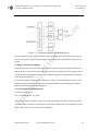
2.3 L298 Full-Bridge driver from National Semiconductor
or
d
L298 Dual Full-Bridge driver is a two H-bridge (back to back connected) IC used in
this project to change the direction of the 2-phase bipolar stepper motor. Direction of the
stepper motor is decided based on how the wirings or the terminals of the 2-phase stepper
motor are energized. From the data sheet [5] L298 Full-Bridge driver has the following
rtf
characteristics: (See Appendix C for electrical characteristics)
of
He
· Operating supply voltage up to 46V
· Total DC current up to 4A
· TTL compatible inputs
· Over temperature protection
· Low saturation voltage
· Logical 0 input voltage up to 1.5V (High noise immunity)
Based on the information from the date sheet [5], we briefly look into the function of the pins
Un
ive
rsi
ty
of the L298 Full-Bridge Driver IC. The pin layout of the L298 are shown in figure 2.3.1
Figure 2.3.1 Pin Connections of the L28 Full-Bridge IC
Pin Functions used in the project:
1. Vs: Supply voltage for the power output stages.
2. Input1and Input2: TTL compatible inputs of the bridge A
Shareef Mohd Aslam
Inverted Pendulum Control
7
Department of Electronic, Communication and Electrical Engineering
Msc. Final Year
University of Hertfordshire
Project Report
Input3 and input4: TTL compatible inputs of the bridge B
Output1 and Output2: Outputs of the bridge A
Outputs3 and Outputs4: Outputs of the bridge B
GND: Ground
SenseA and SenseB: Between this pin and ground is connected the sense resistor to
control the current of the load.
8. Enable A and Enable B: TTL compatible Enable input
9. VSS: Supply voltage for the logic Blocks. A 100nF capacitor must be connected
between the pin and the ground.
or
d
sh
ire
3.
4.
5.
6.
7.
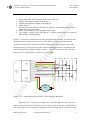
Figure 2.3.2 shows the connection between the L298 Full-bridge driver IC, Z8 controller and
the 2-phase bipolar stepper motor. PA0, PA1, PA2 and PA3 are the outputs from the Z8
controller of PortA are connected to the L298 full-bridge driver Input1, Input2, Input3 and
rtf
Input4 respectively. The four wiring of the 2-phase bipolar stepper motor is connected to the
L298 Full-bridge driver Outputs (output1, output2 …. output4) respectively. The L298 Full-
PA0
PA1 PA2
PA3
5V
12V
GND
Stepper
Motor
Un
ive
rsi
ty
of
He
bridge driver IC is powered by a separate 12V power supply.
Figure 2.3.2 Connection between L298 IC, Z8 Controller and Motor
Diodes D1, D2….D8 are used to protect the L298 full-bridge driver IC. Because in
inductive loads current flow from load to source when a motor accelerates or decelerates for
any reason. These reverse current can damage the L298 full-bridge driver IC. Hence 2A fast
Shareef Mohd Aslam
Inverted Pendulum Control
8
Department of Electronic, Communication and Electrical Engineering
Msc. Final Year
University of Hertfordshire
Project Report
diodes are used to protect the L298 IC from reverse current coming from the load to source by
ire
turning ON when the reverse current exceeds it limit.
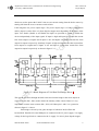
L298 integrates two power output stages. The power output stage is a bridge configuration
and its output is used to drive a 2-phase bipolar stepper motor depending on the states of the
sh
input. Two Enable (Enable A and Enable B) inputs are provided to enable or disable the
device independently of the input signals. If input1 is high and input2 is low then the current
or
d
flow from output1 to output2 and if input1 is low and input2 is high then current flow from
output2 to output1 respectively. Similarly if input3 is high and input4 is low then current flow
from output3 to output4 and if input3 is low and input 4 is high then current flow from
ive
rsi
ty
of
He
rtf
output4 to output3 respectively as shown in figure 2.3.2.
Un
Figure 2.3.2 Block Diagram of L298 Dual Full-Bridge Driver []
The current, that flows through the load comes out from the bridge at the sense output: an
external resistor (RSA ; RSB) used to detect the intensity of this current. Hence it is very
important to connect sense resistors (RSA ; RSB) of 0.5Ω to pins 1 and 15 to a ground as
shown in figure 2.3.2 above.
Each bridge is driven by four gates the input of which are In1;In2:EnA and
In3;In4:EnB. Therefore EnA and EnB pins are connected to the 5V power supply. Vss supply
voltage for the logic blocks is connected to the 5v supply. To drive 2-phase bipolar stepper
Shareef Mohd Aslam
Inverted Pendulum Control
9
Department of Electronic, Communication and Electrical Engineering
Msc. Final Year
University of Hertfordshire
Project Report
motor we require two H-bridges therefore enable both Enable inputs (EnableA and EnableB).
ire
Otherwise the L298 Dual Full-Bridge IC will not drive the 2 phase bipolar stepper motor.
Problem encountered and solution:
The voltage on the Z8 controller pins are 3.3V but the minimum voltage required by
He
rtf
or
d
sh
the L298 full bridge driver is 4.5V. Hence optocoupler is used to increase the voltage.
Figure 2.3.3 Functional Diagram
Figure 2.3.4 Schematic Diagram
ty
of
· Anode
· Cathode
· Not connected
· Emitter
· Collector
· Base
4N25 Optocoupler used in this project. It contains a light emitting diode optically coupled
rsi
to a photo-transistor as shown in above figure 2.3.4. From the data sheet [] it has the
following characteristics:
ive
Feature:
Un
1. Current transform ratio (CTR) min 20% at IF = 10 mA, VCE = 10V
2. input-output isolation voltage (Viso =2500 Vrms)
3. Response time ( tr:typ., 3µs at VCE = 10V, IC = 2mA, RL = 100Ω)
figure 2.3.5 Test circuit for time response
Shareef Mohd Aslam
Inverted Pendulum Control
10
Department of Electronic, Communication and Electrical Engineering
Msc. Final Year
University of Hertfordshire
Project Report
I have taken four opto-couplers for four Z8 controller output pins. Connection for the Opto-
ire
coupler is shown in above figure 2.3.5. Output from the Z8 controller is connected to the
anode terminal and all cathodes are connected to the Z8 controller GND Pin number 39. A 5V
the emitter terminal is connected to the L298 Full-Bridge driver.
sh
power supply is applied across Vcc terminal, all base terminals are grounded and output from
When I am applying the rated supply voltage required by the stepper motor that is
or
d
12V to the L298 Full-Bridge Driver IC, the L298 IC is getting heated up which can damage
the L298 Dual full-bridge driver IC very easily. Therefore a heat sink is attached to L298
Full-Bridge Driver IC which absorbs the heat dissipated by the L298 IC. Hence these avoid
rtf
any damages or burns to L298 driver IC.
He
2.4 HEDS-9140 Incremental Encoder from Hewlett-Packard
In inverted pendulum, the measurement of pole angle, position and direction of
rotation with respect to the upright (absolute zero) position is very important. If the accuracy
of the system is good ( that is if we get the precise values of pole angle and position) then the
of
system is more the robust. Several sensors like potentiometer, shaft encoders and absolute
encoders are available in market. To avoid any friction on the shaft incremental encoders or
ty
the absolute encoders are the right choice because these encoders avoids any mechanical
contacts required to know the pole angle, position or the direction of the pole. But in the
rsi
market absolute encoders are too expensive compare to incremental encoders. After looking
so many encoders and the price of the encoders hence I decided to go for the following
HEDS-9140 three channel optical incremental encoder
HEDS-5140 Code wheel
Un
·
·
ive
encoder.
2.4.1 HEDS-9140
has the following characteristics listed below from the data sheet [6]
(See Appendix D for HEDS-9140 characteristics)
·
·
·
·
·
·
·
Two Channel Quadrature output with Index Pulse
Resolution up to 2000 CPR (counts per revolution)
Low Cost
Easy to mount
No signal Adjustment required
Small size
-40°C to 100°C Operating Temperature
Shareef Mohd Aslam
Inverted Pendulum Control
11
Department of Electronic, Communication and Electrical Engineering
Msc. Final Year
University of Hertfordshire
Project Report
TTL Compatible
Single 5V supply voltage
ire
·
·
HEDS-9140 has two channel quadrature outputs (waveforms out of phase) in addition with a
sh
third channel index output. This index output is a 90 electrical degree high true index pulse
which is generated once for each full rotational of the code wheel. HEDS-9140 is designed
for use with a HEDS-5140 code wheel which has an optical radius of 11.00mm (0.433) (from
or
d
data sheet).
HEDS-9140 is an emitter or detector module. Coupled with a code wheel, this module
rsi
ty
of
He
rtf
translates the rotary motion of a shaft into a three channel digital output.
ive
Figure 2.4.1.1 HEDS-9140 Block Diagram [6]
If we look at the figure2.4.1.1 block diagram, HEDS-9140 contains a single light emitting
Un
diode (LED) as its light source. The light collimated into a parallel beam by means of a single
polycarbonate lens located directly over the LED. Opposite the emitter is the integrated
detector circuit. This IC consists of multiple sets of photo detectors and the signal processing
circuitry necessary to produce the digital waveforms (from data sheet).
Shareef Mohd Aslam
Inverted Pendulum Control
12
Msc. Final Year
University of Hertfordshire
Project Report
or
d
sh
ire
Department of Electronic, Communication and Electrical Engineering
rtf
Figure 2.4.1.2 HEDS-9140 Output Waveform [6]
The code wheel rotates between the emitter and detector, causing the light beam to be
He
interrupted by the pattern of spaces and the bars on the code wheel. Photo diodes which detect
this interrupt are arranged in a pattern that corresponds to the radius and design of the code
wheel. There detectors are placed in such a way that a light period on one pair of detectors
corresponds to a dark period on the adjacent pair of the detectors. Because of this integrating
of
phasing technique, the digital output of channel A is in quadrature with channel B(90° degree
ty
out of phase) as shown in figure below 2.4.1.2 ( from data sheet).
If the code wheel rotates in the direction of the arrow on the top of the module then Channel
rsi
A will lead the Channel B by 90°. If the code wheel rotates in the other direction that is
opposite to the arrow on the top of the module then Channel B will lead the Channel A by
Un
ive
90°. As shown in below figure 2.4.1.3
Shareef Mohd Aslam
Inverted Pendulum Control
13
Msc. Final Year
University of Hertfordshire
Project Report
rtf
or
d
sh
ire
Department of Electronic, Communication and Electrical Engineering
He
Figure 2.4.1.4 HEDS-9140 Channel A(1>) and channel B (2>) Output waveform from
ive
rsi
ty
of
Oscilloscope
Un
Figure 2.4.1.4 Pull –up resistors on HEDS-9140 encoder output [6]
To ensure reliable encoding performance, HEDS-9140 three channel optical
incremental encoder module require 2.7KΩ pull-up resistors on output pins 2, 3 and 5
that is on Channel A, Channel B and channel index output as shown in above figure
2.4.1.4.
Shareef Mohd Aslam
Inverted Pendulum Control
14
Department of Electronic, Communication and Electrical Engineering
Msc. Final Year
University of Hertfordshire
Project Report
CH A
A HCTL-
Z8
Three
CH B
2016/2020
controller
Channel
ire
HEDS-9140
quadrature
CH I
decoder/co
sh
Incremental
Figure 2.4.1.5 Diagrams show typical interface between Z8 controller and the channel
or
d
optical Incremental Encoder module
Problem Encountered and Solution:
rtf
A HCTL-2016/2020 quadrature decoder/counter is not compatible to Z8 controller it
requires external clock with higher frequency than the Z8 controller which is quite difficult to
He
achieve using the available equipments in the lab. Hence this problem can be solved via
software.
In year 2006 Kok Jiann Horng tried to interface between Z8 controller and incremental
encoder via hardware approach, that is using HCTL-2016/2020 quadrature decoder/counter
of
but he is fail to close the inverted pendulum hardware. Hence this problem can be solved
through software approach by using timers. In Z8 controller we have counter option by using
ty
this we can count the number of pulses. Hence there is no need to go for decoder/counter
rsi
circuit.
2.4.2 HEDS-5140 Code wheel
ive
As mentioned earlier code wheel rotates between the emitter and detector, causing the
light beam to be interrupted by the pattern of spaces and bars on the code wheel. The
photodiodes which detects this interrupts are arranged in a pattern that corresponds to the
Un
radius and design of the code wheel. From the data sheet [7] HEDS-5140 two and three
channel code wheel optical encoder mode has the following characteristics:
1. Resolutions from 96 CPR (counts per revolution) to 2048 CPR
2. Code wheel available in glass, film and metal
Shareef Mohd Aslam
Inverted Pendulum Control
15
Department of Electronic, Communication and Electrical Engineering
Msc. Final Year
University of Hertfordshire
Project Report
ire
Three channel
optical
incremental
sh
Shaft
encoder
2-Ph
or
d
bipolar
rtf
stepper
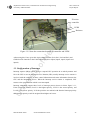
Figure 2.4.2.1 Alignment tool is used to set height of the code wheel
He
Assembly tools required for alignment Code wheel on HEDS-9140 Incremental encoder is for
Un
ive
rsi
ty
of
Centering and Gap-Setting HEDS-8905 alignment tool is required shown in figure 2.4.2.1.
Shareef Mohd Aslam
Inverted Pendulum Control
16
Department of Electronic, Communication and Electrical Engineering
Msc. Final Year
University of Hertfordshire
Project Report
3. Programming and configuration of the Z8 controller
sh
programmed and configured to control the inverted pendulum hardware.
ire
In this chapter, we will see how the Zilog Z8 Encore!® Z8F64200100KIT MCU is
3.1 Overview and Configuration of the Zilog Z8 Encore!® ZF642X
or
d
MCU controller
Specifications and main features of the Zilog Z8 Encore!® Z8F64200100KIT MCU
controller are as follows ( from Z8 Encore! User Manual)[8].
rtf
He
of
ty
ive
·
·
·
·
·
·
·
·
·
·
·
·
20MHz eZ8 CPU
Up to 64KB Flash Memory with in circuit programming capability
Up to 4KB register RAM.
Seven 8-bit (Ports A-G) and one 4-bit (Port H) general purpose input/output (GPIO)
pins
12-channel, 10-bit analog-to-digital converter(ADC)
Two full-duplex 9-bit UARTs with bus transceiver Driver Enable Control
I2C
Serial Peripheral Interface
Two Infrared Data Association (IrDA) compliant infrared encoder/decoders
Up to four 16-bit timers with capture, compare, counter and PWM capability
Watch-Dog timer (WDT) with internal RC oscillator
3-channel DMA
24 interrupts with configuration priority
On-chip Debugger
Power-On reset (POR)
3.0-3.6V operating voltage with 5V-tolerant inputs
rsi
·
·
·
·
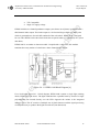
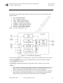
Below figure 3.1.1 shows a diagram of the Z8 Encore!® Z8F64200100KIT MCU controller r
(For convenience purpose Zilog Z8 Encore!® Z8F64200100KIT MCU is know called as Z8
Un
controller in this project report). Among the many features, only certain features of the Z8
controller are used in this project such as GPIO ports, Interrupts and Timers.
Shareef Mohd Aslam
Inverted Pendulum Control
17
Msc. Final Year
University of Hertfordshire
Project Report
or
d
sh
ire
Department of Electronic, Communication and Electrical Engineering
rtf
Figure 3.1.1 Z8 Encore!® 64K serial MCU development board [8]
In this project, Z8 controller works as a interface between the PC (software programming)
He
and the hardware (inverted pendulum). The Z8 controller read the signals from the
incremental encoder on one of the GPIO ports and sends them to PC as input data, and then
according to the output data from PC, the Z8 controller will generate the PWM signal for the
of
2-ph bipolar stepper motor.
ty
3.2 Configuration of general purpose input/output (GPIO)
As mentioned earlier, the 64K series Z8 controller having seven 8-bit ports (Ports A-G) and
rsi
one 4-bit port (Port H) for general purpose input/output (GPIO). Each pin is individually
programmable for input or output operations. Some bits of the ports can be configured for
ive
special functions, such as interrupts, timers and UARTs etc.
In this project, two out of the eight ports are used. 4-pins of the PortA are configured as
output ports (PA0, PA1, PA2 and PA3) and 2-pins of the PortD are configured as input ports
Un
(P3AD and P5AD). The first 4-pins of the port A is connected to the L298 full-bridge driver
to control the direction and current applied to the 2-phase bipolar stepper motor and PortD pin
P3AD is configured for special function (that is for interrupt purpose); an interrupt occurs
when ever P3AD goes in high state the interrupt request allow device to suspend CPU
operation and for CPU to start an interrupt service routine and hence an interrupt service
routine code is executed during this period. 2-pins of PortD are connected to the incremental
encoder output Channel A and channel B.
Shareef Mohd Aslam
Inverted Pendulum Control
18
Department of Electronic, Communication and Electrical Engineering
Msc. Final Year
University of Hertfordshire
Project Report
Four registers for each port provide access to GPIO control, input data, and output data. Port
ire
A-H Address and Control registers are used together to provide access to sub-registers for
port configuration and control (from user manual)
Port Register Mnemonic
Port Register Name
Port A-H sub-registers(select sub-
or
d
PxADDR
sh
Replace “x” with A-H accordingly
registers)
PxCTL
Port A-H Control Register
rtf
(Provides access to sub-registers)
Port A-H Input Data Register
PxOUT
Port A-H Output Data Register
He
PxIN
Port sub-Register Mnemonic
Port Register Name
PxDD
Data Direction
of
PxAF
PxOC
ty
PxDD
rsi
PxSMRE
Alternate Function
Output Control (open-drain)
High Drive Enable
STOP Mode Recovery Source
Enable
ive
Table 3.2.1 GPIO Port Registers and Sub-Registers
Un
1. PxADDR is the address register used to select port sub-registers. Three port subregisters that are used in this project are
· ALT_FUN: Alternate function sub-register. Used to configure a certain bits
of a certain port as alternative function.
· DATA_DIR: Data direction sub-register. Used to configure port pins as input
or output
· OUT_CTL: Output control sub-register. Used to enable or disable the port
drain.
2. PxCTL is the control register; if the address register is used to select a sub-register
then the control register is used to configure a sub-register.
3. PxIN is the input register; 8-bit input data is stored in this register when a GPIO port
is set as input. Input data register are Read-Only.
4. PxOUT is the output register, 8-bit output data is stored in this register before sending
out from output GPIO ports.
Shareef Mohd Aslam
Inverted Pendulum Control
19
Department of Electronic, Communication and Electrical Engineering
Msc. Final Year
University of Hertfordshire
Project Report
ire
In my project I have chosen Port A as output. Configure PortA as output,
Alternate Functions:
I am not using any alternate functions of PortA like timers, UARTs or I2C of PortA.
sh
So the 8-bit configuration value for the control register will be 00000000 = 0x00H.
PAADDR = ALT_FUN;
or
d
PACTL = 0x00;
He
rtf
Data Direction:
of
Table 3.2.1 Data Direction Sub-Registers [8]
0 = Output. Data in the PortA Output Data Register is driven onto the port pin.
The Output is tri-stated.
ty
1 = Input. The port pin is sampled and the value written into the portA Input Data Register.
rsi
I am configuring PortA as Output, so the 8-bit configuration value for the control register will
be 00000000 = 0x00H
ive
PAADDR = DATA_DIR;
PACTL = 0x00;
Un
Output Control:
Shareef Mohd Aslam
Inverted Pendulum Control
20
Department of Electronic, Communication and Electrical Engineering
Msc. Final Year
University of Hertfordshire
Project Report
Table 3.2.2 Port Output Control Sub-Registers [8]
ire
0 = drain enable
1 = drain disable
Here drain values for all the ports are enabled. So, the 8-bit configuration value for control
sh
register will be 00000000 = 0x00H. Otherwise high value is not driven if the drain has been
disabled by setting the corresponding port output control register bit to 1.
or
d
PAADDR = OUT_CTL
PACTL = 0x00;
rtf
Port Output (PAOUT):
These bits contain the data to be driven out from the port pins. The values are only driven if
the corresponding pin is configured as an output and the pin is not configured for alternate
ty
of
He
function operation.
rsi
Table 3.3.3 PortA Output data sub-registers [8]
ive
POUTx = Port Output
0 = Drive a logical 0 (Low)
1 = Drive a logical 1(high). High value is not driven if the drain has been disabled by setting
Un
the corresponding port output control register bit to 1.
Where “x” indicates the specific GPIO Port pin number
In my project motor has 4 leads; hence the PAOUT is configured based on the energizing
sequence of the 2-phase bipolar stepper motor winding.
I have chosen PA0, PA1, PA2 and PA3 as output pins of PortA.
If we want the 2-phase bipolar stepper motor to rotate in clockwise direction or anticlockwise,
then the corresponding pin is configured as an output.
Shareef Mohd Aslam
Inverted Pendulum Control
21
Msc. Final Year
University of Hertfordshire
Project Report
ire
Department of Electronic, Communication and Electrical Engineering
First step
PAOUT = 0x05
Case 1:
PAOUT = 00000101
PAOUT = 0x09
First step
PAOUT = 00001001
Break;
Case 2:
Second step
PAOUT = 0x06
PAOUT = 00000110
PAOUT = 0x0A
Second step
PAOUT = 00001010
Break;
Case 3:
Third step
PAOUT = 0x0A
He
Break;
Case 2:
rtf
Break;
or
d
Case 1:
For Anti-Clockwise
sh
For Clockwise
PAOUT = 00001010
of
Break;
Case 4:
Fourth step
PAOUT = 00001001
ty
PAOUT = 0x09
Break;
Case 3:
PAOUT = 0x06
Third step
PAOUT = 00000110
Break;
Case 4:
PAOUT = 0x05
Fourth step
PAOUT = 00000101
Break;
rsi
Table 3.2.4 Energizing sequence for clockwise and anticlockwise
I wrote this code in C programming and I have observed its output on the LEDS connected on
ive
the bread board in series with the RL = 100Ω resistance to avoid any damages to the LEDS.
Hence the LEDS are blinking in right sequence for both clockwise and anticlockwise as
Un
shown in below figure 3.2.5.
Shareef Mohd Aslam
Inverted Pendulum Control
22
Department of Electronic, Communication and Electrical Engineering
Msc. Final Year
University of Hertfordshire
Project Report
Z8 micro-
LEDS
Resisters
rtf
or
d
sh
ire
controller
He
Figure 3.2.5 show the connection between Z8 controller and LEDS
After testing this, I have given this 4-pin output of PortA (PA0, PA1, PA2 and PA3) and
GND from Z8 controller to the L298 Full-Bridge driver inputs (input1, input2, input3 and
of
input4).
ty
3.3 Configuration of Interrupt
Interrupt requests (IRQs) allow device to suspend CPU operation in an orderly manner and
rsi
force the CPU to start an Interrupt Service Routine (ISR), usually interrupt service routine is
involved with the exchange of data, control information and status information between the
ive
CPU and the interrupting device. When the Interrupt service routine is completed, CPU
returns to the operation from which it was interrupted.
Interrupt controllers support three levels of interrupt priority shown in below figure 3.3.1,
Un
From (Zilog user manual) Level3 is the highest priority, Level2 is the second priority, and
Level1 is the lowest priority. If all the priorities are enabled with identical interrupt priority
then interrupt priority would be assigned from highest to lowest.
Shareef Mohd Aslam
Inverted Pendulum Control
23
Msc. Final Year
University of Hertfordshire
Project Report
rtf
or
d
sh
ire
Department of Electronic, Communication and Electrical Engineering
Figure 3.3.1 Interrupt controller Block Diagram [8]
He
In Z8 controller the ports support interrupts, they are PortA, PortC and PortD. I have chosen
PortA for energizing 2-phase bipolar stepper motor. I have chosen PortD for interrupt in my
project.
Configure PortD for interrupt:
of
2-bits of PortD are used to read the output signal from the incremental encoder channel and
channel B. Here I have chosen Pin3 and pin5 of PortD as an input to the Z8 controller. Pin3 is
ty
connected to the incremental encoder output channel A and pin5 is connected to incremental
encoder output channel B.
rsi
If code wheel rotate in the direction of the arrow of the encoder module then channel A will
lead the channel B otherwise channel B will lead the channel A. One interrupt is enough to
know which channel is leading and lagging.
ive
3.3.1 Interrupt Port Initialization:
Void init_p3ad (void)
Un
SET_VECTOR (P3AD, isr_p3ad)
The interrupt request 1 (IRQ1) register stores interrupt requests for both vectored and polled
interrupts. When a request is presented to the interrupt controller, the corresponding bit in the
IRQ1 register becomes 1 (From Zilog User Manual).
Shareef Mohd Aslam
Inverted Pendulum Control
24
Msc. Final Year
University of Hertfordshire
Project Report
sh
ire
Department of Electronic, Communication and Electrical Engineering
or
d
Table 3.3.2 Interrupt Request port initializatioin [8]
PADxI = Either PortA or PortD interrupt request
0 =No interrupt request is pending for GPIO PortA or PortD
1 = An interrupt request from GPIO PortA or PortD is awaiting service
rtf
Where “x” indicates the specific GPIO Port pin number.
Firstly, we have to initialize the PortD pin numbers 3 and 5.
He
I am not using any alternate function of PortD that is timers, UART or Watch-Dog timer. So
the 8-bit configuration value of control register values 00000000 = 0x00H
PDADDR = ALT_FUN;
of
PDCTL = 0x00;
PDADDR = DATA_DIR;
PDCTL |= 0x28
ty
0 = Output. Data in the PortD Output Data Register is driven onto the port pin.
1 = Input. The port pin is sampled and the value written into the portA Input Data Register.
rsi
The Output is tri-stated.
Configure the data direction of 2-bits of PortD that is pin3 and pin5 by writing the desired
ive
configuration value to the control register. So the 8-bit configuration value for the control
register will be 00101000 = 0x28H.
Un
3.3.2 Set Interrupt priority:
The IRQ1 Enable High and Low bit registers form a priority. Priority is generated by setting
bits in each register, How to set interrupt priority is shown in below table (From Zilog User
Manual).
IRQ1ENL[x]
Priority
Description
IRQ1ENH[x]
Shareef Mohd Aslam
Inverted Pendulum Control
25
Department of Electronic, Communication and Electrical Engineering
Msc. Final Year
University of Hertfordshire
Project Report
0
Disabled
Disabled
0
1
Level 1
Low
1
0
Level 2
Nominal
1
1
Level3
High
sh
ire
0
Where x indicates the register bits from 0 through7
or
d
Table 3.3.3 Priority configuration table
rtf
In my project interrupt is very important to know in which direction pendulum is rotating.
Hence i have chosen high interrupt priority that is Level3 by setting both Enable High and
He
Enable Low bit registers of P3AD of PortD to 1. So the 8-bit configuration value of Interrupt
request priority is (IRQE) will be 00001000 = 0x08
IRQ1E0 |= 0x08;
of
IRQ1E1 |= 0x08;
ty
3.3.3 Interrupt Edge selection Register
rsi
Interrupt edge selection register determines whether an interrupt is generated for the falling
Un
ive
edge or rising edge on the selected GPIO port input pin.
Table 3.3.4 interrupt Edge Select Register [8]
IESx = Interrupt Edge Select x
0 = An interrupt request is generated on the falling edge of the PDx input.
1 = An interrupt request is generated on the rising edge of the PDx input
Where “x” indicates the specific GPIO Port pin number
Shareef Mohd Aslam
Inverted Pendulum Control
26
Department of Electronic, Communication and Electrical Engineering
Msc. Final Year
University of Hertfordshire
Project Report
Here I have chosen interrupt request on rising edge. So the 8-bit configuration value of
ire
Interrupt edge select register (IRQES) will be 00001000 = 0x08
3.3.4 Interrupt Port Select:
sh
IRQES |= 0x28;
The interrupt port select register determines the port pin that generates interrupts. This
He
rtf
or
d
register allows either PortA or PortD pins to be used as interrupts.
Table 3.3.5 interrupt Port Select Register [8]
PADxS = PAx/PDx Selection
of
0 = PAx is used for the interrupt for PAx/PDx interrupt request
1 = PDx is used for the interrupt for PAx/PDx interrupt request
Where “x” indicates the specific GPIO Port pin number
ty
I have chosen PortD for Interrupt request. So the 8-bit configuration value for the
ive
IRQPS |= 0x28
rsi
interrupt select port register (IRQPS) will be 00101000 = 0x28H
3.4 Configuration of Timer
The internal Timer1 and Timer2 is used in this project to generate two Pulse Width
Un
modulation (PWM) externally using another Z8 controller (in place of encoder temporarily),
because my hardware was not ready. There were so many disturbances in the engineering
department because of school renovation. Therefore I generated the Pulse width modulation
which is similar to the output of the three channel optical incremental encoder.
The Z8 controller has 4 internal timers they are Timer0, Timer1, Timer2 and Timer3. Timer1
and Timer 2 are configured as PWM mode, PWM signal are send from PC0 (PC0_T1OUT)
and PC7 (PC7_T2OUT) to the main Z8 controller pins PD3 and PD5 to read the output signal
Shareef Mohd Aslam
Inverted Pendulum Control
27
Department of Electronic, Communication and Electrical Engineering
Msc. Final Year
University of Hertfordshire
Project Report
generated by the temporarily Z8 controller (Used in place of encoder). Each timer has 8-bit
ire
registers namely
ive
rsi
ty
of
He
rtf
or
d
sh
· TxL = Low Byte Register
· TxH = High Byte Register
· TxRL = PWM Low Byte Register
· TxRH = PWM High Byte Register
· TxPWML = PWM Low Byte Register
· TxPWMH = PWM High Byte Register
· TxCTL0 = Timer Control 0 Register
· TxCTL1 = Timer Control 1 Register
Where “x” is the timer number ( 0 to3)
Figure 3.4.1 Timer Block Diagram [8]
The timer input is the system clock, the timers count up to 16 bit PWM match value stored in
TxPWMH and TxPWML byte registers. When the timer count value matches the PWM
Un
value, the timer output toggles.
If TPOL (Timer input/output polarity) bit in the timer control 1 register is (From Zilog
manual)
·
·
Set to 1, the Timer Output signal begins as High (1) and then transitions to a Low (0)
when the timer value matches the PWM value. The timer Output signal returns to a
High (1) after the timer reaches the Reload value and is reset to 0001H.
Set to 0, the Timer Output signal begins as Low (0) and then transitions to a High (1)
when the timer value matches the PWM value. The timer Output signal returns to a
High (1) after the timer reaches the Reload value and is reset to 0001H.
Shareef Mohd Aslam
Inverted Pendulum Control
28
Msc. Final Year
University of Hertfordshire
Project Report
He
rtf
or
d
sh
ire
Department of Electronic, Communication and Electrical Engineering
Figure 3.4.2 Timer Control 1 Register [8]
Steps for configure a Timers for PWM mode (Zilog user Manual)
ty
of
1. First Configure the 8-bit Timer control 1 register,
· Disable the timer,
· Set the TPOL,
· Prescale value and
· And configure the timer for PWM mode.
TxCTL1 = 01101101 =
Un
ive
rsi
2. Write the Timer High and Low Byte registers to set the starting count value.
3. Write to the PWM high and Low Byte registers to set the PWM value
4. Write to the Timer Reload High and Low Byte registers to set the Reload value. The
Reload value must be greater than the PWM value
5. Configure the PortC pin for the Timer Output alternate function
6. Write the timer control 1 register to enable the timer.
The PWM period is calculated using the following equation:
Reload value x Prescale value
PWM period (s) =
System Clock Frequency (Hz)
The TPOL is set to 1, the ratio of the PWM output High time to the total period is
calculated by the following equation
Shareef Mohd Aslam
Inverted Pendulum Control
29
Department of Electronic, Communication and Electrical Engineering
Msc. Final Year
University of Hertfordshire
Project Report
PWM Value
x 100
Reload Value
ire
PWM Output High Time Ratio (%) =
For example if Reload value is FFFF, the prescale value is set to 32 and system clock
sh
frequency of Z8 controller is 18.432MHz, then the PWM period is
or
d
65536 x 32
PWM period =
18432000
ive
rsi
ty
of
He
= 113.7 ms
rtf
= 0.1137 s
Un
Figure 3.4.2 Timer1 (1>) and Timer (2>) Output waveform from oscilloscope
Two pulses are created similar to the encoder module output that is 90 degree out of phase by
giving delay between two timers as shown in figure 3.4.2. The phase difference between two
timers can be adjusted by setting delay time.
Therefore by changing the PWM value in the Timer PWM High (TxPWMH) and Low
(TxPWML) Byte registers, we can change the duty cycle of the modulated PWM pulse.
Shareef Mohd Aslam
Inverted Pendulum Control
30
Department of Electronic, Communication and Electrical Engineering
Msc. Final Year
University of Hertfordshire
Project Report
4. Fuzzy interference system (FIS)
ire
In this chapter, discussion will be on Fuzzy Interference controller, used to control the
inverted pendulum hardware. Discussions will be on creating fuzzy sets, membership
sh
function, fuzzy rules and design considerations.
4.1 FIS introduction
Fuzzy interference system is the process of mapping between given inputs to an output, using
or
d
the theory of fuzzy logic. Fuzzy logic mimics the human decision making by using fuzzy
rules with vague terms. It represents expert knowledge with fuzzy sets
The concept of fuzzy logic was proposed by Lofti Zadeh, A professor at the University of
rtf
California at Berkley. Fuzzy logic can be implemented on hardware (inverted pendulum),
software (simulation) or on both. Fuzzy logic is simplest way of mapping between input and
He
output.
The principle of fuzzy inference system is a list of if-then statements called rules. Before we
build a system that interprets rules we have to define the linguistic variables (pole angle,
angular velocity and torque) and linguistic values (low, medium, and high) called
of
membership function and fuzzy sets.
A fuzzy set can be simply defined as a set with fuzzy boundaries [13]
ty
Let X be the universe of discourse and its elements be denoted as x. in classical theory, crisp
set A of X is defined by a function fA(x) called the characteristic function of A [13].
ive
Where,
rsi
fA(x) : X→ (0,1)
This function map universe of discourse X to a two elements. For any elements of x of
Un
universe X, fA(x) (characteristic function) is equal to 1 if x is an element of set A and equal to
zero if x is not an element of set A.
In fuzzy theory, fuzzy set A of universe X is defined by function µA(x) called membership
function of set A [13].
µA(x): X→ (0,1)
Where,
Shareef Mohd Aslam
Inverted Pendulum Control
31
Department of Electronic, Communication and Electrical Engineering
Msc. Final Year
University of Hertfordshire
Project Report
ire
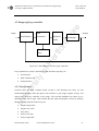
4.2 Design of fuzzy controller
Fuzzification
Evaluation
Defuzzifi
Output
Pendulum
or
d
cation
Inverted
sh
Rule
Input
rtf
Fuzzy rule
He
base
of
Figure 4.2.1 Block diagram of Fuzzy logic controller
Fuzzy interference system is basically divided into three steps they are
Fuzzification
·
Rule evaluation and
·
Defuzzification
rsi
ty
·
ive
4.2.1 Fuzzification
Fuzzifier takes the input variables based on that it will determine the fuzzy set and
membership functions. Here the input to the fuzzifier is pole angle, angular velocity and
Un
output from the fuzzy controller is the torque. The inverted pendulum can rotate in two
directions either left or right. Hence define the pole angle and angular velocity by defining
the membership function for the fuzzy sets
·
Negative high (NH)
·
Negative low (NL)
·
Zero (Zero)
·
Positive low (PL)
·
Positive high (PH)
Shareef Mohd Aslam
Inverted Pendulum Control
32
Department of Electronic, Communication and Electrical Engineering
Msc. Final Year
University of Hertfordshire
Project Report
Similarly for toque
Anti-Clockwise (AL)
·
Zero (Zero)
·
Clockwise (CL)
ire
·
sh
The fuzzy set and membership function for the input and output variables are shown figure
He
rtf
or
d
4.2.1.1.
Un
ive
rsi
ty
of
a) Input membership functions
b) Output membership functions
Figure 4.2.1.1 Memebership functions a) Input membership functions and b)
output membership fucntions
4.2.2 Rule evaluation
Shareef Mohd Aslam
Inverted Pendulum Control
33
Department of Electronic, Communication and Electrical Engineering
Msc. Final Year
University of Hertfordshire
Project Report
In this stage fuzzy interference system takes the fuzzified inputs and applies them to the fuzzy
ire
rule base. If a fuzzy rule has multiple rules then fuzzy operator (AND or OR) is used to create
a single number which represents the truth value of the fuzzy rule. Some rules for the inverted
rsi
ty
of
He
rtf
or
d
sh
pendulum is created and shown in below figure using MATLAB FIS editor.
ive
Figure 4.2.2 Show the fuzzy rules
4.2.3 Defuzzification
Un
The defuzzifier takes the fuzzy interference system output and creates a single crispy output.
There are several defuzzification methods, but probably the most popular one is the centroid
technique. It finds the point where a vertical line would slice the aggregated set into two equal
masses. Mathematically this centre of gravity (COG) can be expressed as [14]
Shareef Mohd Aslam
Inverted Pendulum Control
34
Department of Electronic, Communication and Electrical Engineering
Msc. Final Year
University of Hertfordshire
Project Report
ire
Because of limited time i was unable to do FIS simulation, I have just created an example of
rsi
ty
of
He
rtf
or
d
sh
fuzzy sets, membership functions and rules based on the input variables to the fuzzy system.
Un
ive
Figure 4.3.3 Surface of the fuzzy logic controller
Shareef Mohd Aslam
Inverted Pendulum Control
35
Department of Electronic, Communication and Electrical Engineering
Msc. Final Year
University of Hertfordshire
Project Report
5. Implementation and testing
ire
In this chapter, inverted pendulum hardware is tested. The problems and difficulties faced for
interfacing between sensor and Z8 controller are discussed.
sh
5.1 Incremental encoder module
When I was trying to interface between Z8 encore controller and three channel incremental
encoder module I faced a wiring problems. Because the first link (horizontal link) which is
or
d
directly connected to the 2-phase bipolar stepper motor shaft is rotating by 360 degrees. I
made the order for adjusting code wheel in incremental encoder but I haven’t got it. So there
is a slip between the code wheel and the shaft which is giving a bit noisy or distortion in the
rsi
ty
of
He
rtf
output signal. The output of the incremental encode is shown in figure 5.1.1
ive
Figure 5.1.1 HEDS-9140 incremental output waveform from oscilloscope
5.2 Close the Inverted Pendulum Hardware
Un
The signals generated by the three channel incremental encoder are send to the Z8 encoder
development board port. Initially, I was planned to go for timers which will count the
incoming pulses generated by the encoder and gives me the pole angle, pole position and
velocity of the system.
Average velocity = (Position2 - Position1)/ time
Because of limited time period and technical problems, I was unable to do calculation of the
inverted pendulum system. So finally I changed my mind to use interrupts. because if we look
at the incremental encoder output waveforms, they are in quadrature (approximately 90
Shareef Mohd Aslam
Inverted Pendulum Control
36
Department of Electronic, Communication and Electrical Engineering
Msc. Final Year
University of Hertfordshire
Project Report
degree out of phase), mean if channel A leading channel B then the motor will be rotate in
ire
clockwise direction and if channel A lagging channel B then the motor will rotate in anticlockwise direction. Therefore one interrupt is enough to know which channel is lagging and
which channel is leading. So I wrote an interrupt service routine code which will simply look
sh
the 2-bit binary data on Z8 controller PortD based on that it will rotate the 2-ph bipolar
stepper motor. Here I have chosen PortD pins (3 and 5) for Z8 controller input. I have chosen
He
rtf
or
d
pin3 for interrupt.
Z8 controller
of
output
Z8
input
Un
ive
rsi
ty
controller
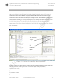
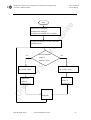
Figure 5.2.1 Software for controlling Inverted pendulum
Figure 5.2.1 and 5.2.2 shows how the values of the Z8 controller output Port A pin values are
changing (PAOUT) with respect to the Z8 controller input PortD pins (PDIN).
if (PDOUT &= 0x20)
{
dir_switch() = 0x00
}
Shareef Mohd Aslam
Inverted Pendulum Control
37
Department of Electronic, Communication and Electrical Engineering
Msc. Final Year
University of Hertfordshire
Project Report
else
ire
{
dir_switch () = 0x01
}
sh
Every time an interrupt occurs the controller sees the PD5 ( PortD pin 5) value if it low then
the dir_switch value is 0x00 means the motor rotates in clockwise direction and if PD5 value
He
rtf
or
d
is high then dir_switch is 0x01 hence the motor rotates in clockwise direction
Z8 controller
of
output
Z8
input
ive
rsi
ty
controller
Un
Figure 5.2.2 Software for controlling Inverted pendulum
The test was completed successfully and I have demonstrated the close loop inverted
pendulum hardware to my supervisor.
7. Project Management
Shareef Mohd Aslam
Inverted Pendulum Control
38
Department of Electronic, Communication and Electrical Engineering
Msc. Final Year
University of Hertfordshire
Project Report
ire
In this chapter, we will discuss the time management, budget management and resources in
the lab for the inverted pendulum control project
sh
7.1 Time Management
Inverted pendulum is a real-time control system. It need a lot of reading in different areas like
or
d
mechanical, computer, electronics, electrical and control system in order to understand the
fundamental and basic concepts. The actual time plan was quite close to the initial plan
proposed, because of some technical and practical works there are some delays in time
rtf
compare to the proposed time table
He
7.1.1 Extra time spend on selecting components and building inverted
pendulum hardware
I struggled a lot for selecting inverted pendulum components because of low budget. When I
of
was going for cheap components it is not compatible to the other components. A lot of
research and test have made, I spend a lot of my project time on selecting the right
ty
components and building the inverted pendulum hardware. There is lots of delay in getting
my components. Still I haven’t got the code wheel alignment toolbox. Design and build the
rsi
inverted pendulum hardware. Test the each part or component separately and then connect to
the inverted pendulum hardware to avoid any damages. I have designed the supporting
.
ive
structure for inverted pendulum.
7.1.2 Extra time spend on programming, configuring the Z8 encore
Un
microcontroller development board.
In the initial time plan, the programming of Z8 controller is not included. This is one of the
biggest challenging and time consuming area. A lot of time is spend on programming to
interface between stepper motor, controller and PC. I have to look for C complier software
provided by the ZDS II development board. Again because of technical problem as I said
earlier I have to look for some other sort of resources. That is instead of incremental encoder I
used PWM to generate a pulses which is similar to the incremental encoder module. Again I
Shareef Mohd Aslam
Inverted Pendulum Control
39
Department of Electronic, Communication and Electrical Engineering
Msc. Final Year
University of Hertfordshire
Project Report
have to look for its specifications and configurations so I used another microcontroller to
ire
generate pulses which has typically increased the hardware complexity.
I spend some time in learning C language; I learned different syntax of C language.
The software which is available in the electronic labs is not compatible to the Z8 controller
sh
development board so I have to install the appropriate software to interface between PC and
or
d
Z8 controller.
7.2 Budget Management
This is another one of the challenging area for me. MSc students are allowed to spend 60£
rtf
budget for there projects. For example, If I am going for stepper motor and motor driver
board it is only costing me around 55£ and more. However with the help of lab technician
He
John Wilmot, I manage to get hardware for my project. Table 6.2.1 shows all the components
used to build the inverted pendulum hardware.
Z8F64200100
development
board
optical
Quantity x cost
UH Store
1 x £ 34.99
Hewlett
rsi
Three channel
Zilog
Supplier
ty
Zilog Encore!
of
Parts/components Manufacturer
1 x £ 29.73
Packard
Farnell
Three channel
Hewlett
Farnell
Code wheel
Packard
L298 Dual Full-
National
Bridge Driver
Semiconductor
Farnell
Bearings
RS
RS
ive
incremental
Un
encoder module
Shareef Mohd Aslam
1 x £ 15.14
1 x £ 2.40
Inverted Pendulum Control
2 x £ 3.78
40
Department of Electronic, Communication and Electrical Engineering
Msc. Final Year
University of Hertfordshire
Project Report
Hewlett
alignment tool
Packard
Farnell
1 x £ 6.46
ire
HEDS-5140 code
1
for Z8 controller
-
UH store
Wooden Base
-
UH Store
2-phase bipolar
Crouzet
stepper motor
or
d
pins
1
-
Hardware with
Pendulum
-
UH Store
1
90.29
ty
of
6mm shaft (Fixed
UH Store
He
pendulum
1
rtf
for Inverted
Total Cost
1
UH Store
Supporting stand
on first link)
sh
25 Pin IC socket
ive
rsi
Table 6.2.1 Components and Cost
6.3 Equipments and Resources used in laboratory
Two power supply is used, one for encoder (5V), Opto-coupler(5V) and L298
Dual Full-Bridge driver (12V)
ZDS-II Z8 encore! controller software for debugging, compiling the C program
An oscilloscope for waveform display
Multimeter for testing circuit ( voltage and current)
Breadboards and wires for circuit connections
Un
·
·
·
·
·
Shareef Mohd Aslam
Inverted Pendulum Control
41
Department of Electronic, Communication and Electrical Engineering
Msc. Final Year
University of Hertfordshire
Project Report
6. Conclusions and further work
ire
This is the last chapter of the project report. In this chapter Project conclusion and further
sh
potential work for this project are highlighted.
6.1 Conclusion
The aim of the project is to design, build and implement FIS to the inverted pendulum
The inverted pendulum hardware is
or
d
hardware to balance a pole in upright position.
successfully built. I have closed the inverted pendulum loop and I have tested this hardware. I
observed how the direction of the inverted pendulum is changing based on the direction of the
rtf
inverted pendulum to balance the pole in upright position. The basic idea of this control
system is using a Z8 encore microcontroller which acts as an interface between inverted
He
pendulum hardware and PC (software). The dynamically changing inverted pendulum
variables (pole angle, position and direction) which are obtained from incremental encoder
are send to the PC and simultaneously the output generated by the PC using C programming
in ZDS II Z8 encore software is given to the Z8 encore controller, which will generate the 8-
of
bit binary data for the stepper motor. Based on this 8-bit binary data stepper motor will rotate
in either forward or backward direction, by giving the desired movement to the first link, the
rsi
6.2 Achievements
ty
pendulum which is linked to this first link is kept on the upright position.
Because of time limit, technical problems, limited resources, and practical problems, this
ive
project is partially completed. Even though I tried my best to complete and at the beginning
everything was going smoothly but at the end of the project my hardware was not ready
because of so many disturbances in the university.
Un
The frame for the inverted pendulum is designed and build. This has taken plenty of time and
one more issue is fix the incremental encoder on shaft which is directly connected to the
pendulum. Practical work consumes a lot of time because everyday a new problem arises. For
example when i was trying to interface between Z8 controller and H-bridge the output voltage
on the Z8 controller is not sufficient for L298 dual full-bridge IC to drive 2-phase bipolar
stepper motor. Hence Opto-coupler are used to increase the voltage. Finally I completed the
inverted pendulum hardware, and I have tested this hardware. I have seen how the 8-bit of the
Z8 controller are changing based on the inverted pendulum angle, which are obtained through
Shareef Mohd Aslam
Inverted Pendulum Control
42
Department of Electronic, Communication and Electrical Engineering
Msc. Final Year
University of Hertfordshire
Project Report
the incremental encoder and send to the Z8 microcontroller GPIO pins. Finally the inverted
ire
pendulum hardware is build and tested.
I have generate the two output waveforms (pulses) using two timers which are very similar to
the incremental encoder output and I have calculated the pulse width modulation period in the
sh
mean time when my hardware was not ready, because the manufacturing department said they
are not going to complete my hardware (supporting structure) because they have packed there
or
d
stuff to move to some other place, because renovation or construction is taking place in the
manufacturing department. John Wilmot helped me a lot, he requested in manufacturing
department and finally i got the inverted pendulum hardware.
After I get the inverted pendulum as I said earlier I said one issue how to fix the incremental
rtf
encoder on one end of the shaft, it has created a lot of trouble. We have to look what is the
best possible way to fix this encoder on the shaft; finally we manage to fix the incremental
He
encoder on the shaft. I ordered the code wheel alignment tool but till the end of the project I
haven’t got it.
Software part was the biggest challenge for me, because I don’t know anything about the
of
programming. I have gone through C programming books to learn about C coding. Dr David
Lee helped me a lot in this software part and he explained me about the coding. Finally at the
end I wrote a program to run a 2-phase bipolar stepper motor. Firstly I have tested this code
ty
on a breadboard and after seeing that the LEDs which are connected on the bread board are
blinking in a correct sequence of pattern then I have giving this connections to the dual full
rsi
bridge driver to run the motor. Finally I have tested the stepper motor; the 2-phase bipolar
stepper motor changing its direction based on the 8-bit binary data presented to the stepper
ive
motor terminals for energizing the motor windings.
Furthermore, the study and research on Z8 controller to configure for this project is gone in
much depth. This Z8 controller configuration is also one of the challenging part for this
Un
project. The suitable ports and pins have been chosen and assigned for particular purposes.
The control and sub-registers for each port are studied to configure the Z8 encore controller
for particular tasks like GPIO for receiving data and sending date from encoder to the stepper
motor respectively, timers to generate output waveforms which are very similar to the
incremental encoder output and interrupts to know which channel is leading and which
channel is lagging. Finally, the connections of the incremental encoder, Z8 encore
development board controller, motor and PC has been established.
6.3 Overall comment on this project
Shareef Mohd Aslam
Inverted Pendulum Control
43
Department of Electronic, Communication and Electrical Engineering
Msc. Final Year
University of Hertfordshire
Project Report
Even though FIS controller has not been developed and implemented on the real-time
ire
inverted pendulum hardware. By using a C code which is compiled and debugged in
ZDS II C complier provided by the ZILOG Z8 encore development board, i control
the pole of the inverted pendulum hardware. So finally we can say that for nonlinear
sh
systems like inverted pendulum can be controller by closing the loop of the system by
using appropriate sensors like encoders. FIS controller are quite reliable for this type
or
d
of systems because just by closing the loop of the inverted pendulum we cant get the
desired position of the inverted pendulum in non-linear state.
rtf
6.4 Potential Further Work
6.4.1 Problems and Difficulties
He
Inverted pendulum hardware is completely built, but the only problem in this hardware is the
friction between the first link and the shaft. As I said earlier manufacturing department was is
in so hurry that they just build the hardware. Even though I used the bearing I was unable to
of
reduce the friction between shaft and link. I think it will be fine if we change the shaft rod
because the shaft rod is not smooth, I mean it has got some rough surface (bends).
Although the inverted pendulum hardware is tested using C programming compiled and
ty
debugged in ZDS II C compiler. But still I am not sure these coding work properly, therefore
if required try to modify the program.
rsi
6.4.2 Further work
The performance of the inverted pendulum is limited by the low-budget. If a further work in
ive
this area is required, then following things have to changed
Instead of incremental encoder I will prefer the absolute encoders which give me the exact
position of the shaft in one rotation. No need to count the pulses for calculating the pole
Un
position. Which will substantially decreases the burden on processor (Z8 controller)
performance or hardware complexity (if we are using increment decoder/counter).
Although inverted pendulum hardware is completed, but still some modification have to be
done to improve the performance of the system specially shaft which is fixed on the first link
has to be changed to reduce the friction.
Design the FIS controller and implement this fuzzy interference system controller on the
inverted pendulum hardware. Learn how to interface between host PC and Z8 controller using
UARTs .
Shareef Mohd Aslam
Inverted Pendulum Control
44
Department of Electronic, Communication and Electrical Engineering
Msc. Final Year
University of Hertfordshire
Project Report
Reference:
Un
ive
rsi
ty
of
He
rtf
or
d
sh
ire
1. Ye Zhang “Inverted pendulum with ANFIS controller”, Project Report Master of
Engineering, University of Hertfordshire, August 2005.
2. Kok Jiann Horng “Close the loop on the inverted pendulum hardware”, Project
Report Master of Engineering, University of Hertfordshire, September 2006.
3. T.Yamakawa, “ Stabilization of an inverted pendulum by a high speed fuzzy logic
controller hardware system”, Fuzzy sets and systems,, Vol.32, no,2, pp 161-180,1989.
4. Data sheet, “2-Phase Bipolar Stepper Motor”,
http://www.crouzet.com/catalogue_web/int/eng/293/Stepper-motors-Direct-drivestepper-motors-ENG-1201.htm
5. Data sheet “ L298 Dual Full-bridge driver”
http://www.st.com/stonline/products/literature/ds/1773/l298.pdfmcv
6. Data sheet “HEDS-9140 Incremental Encoder”
http://www.farnell.com/datasheets/6186.pdf
7. Data sheet “ HEDS-9140 Code Wheel” http://www.farnell.com/datasheets/16616.pdf
8. Dr. David Lee , “ Neurofuzzy and cybernetics”, University of Hertfordshire lecture
notes, year 2007
9. Zilog application note: “ A stepper motor controller using a ZILOG Encore! MCU”,
www.zilog.com
10. Perminder singh thiara, “ DSP based fuzzy logic controller for an inverted
pendulum”, Final Year Report, University of Hertfordshire, April,2001.
11. Anderson, M.J and Grantham, W.J., “ Lyapunov Optimal Feedback Control of a
Nonlinear Inverted Pendulum”,Journal of Dynamic Systems, Measurement and
Control, Vol.111,pp.554-558, 1989.
12. Sheng Liu,Lihui Cui,Jie Chen and Ming Bai, “ Research of Rotary Inverted
Pendulum Using Fuzzy Strategy Based on Dynamic”, Proceedings of the 4th world
congress on intelligent control and automation, Shanghai, P.R, China june 2002.
13. Micheal Negnevitsky, “ Artificial Intelligence- A Guide to Intelligent systems”, first
edition,2002.
14. Lily Meng , “ Neurofuzzy and cybernetics” ,University of Hertfordshire lecture notes,
year 2007
15. Zilog product specification, “Z8 encore! 64K series High performance 8-bit
microcontroller product specifications”. www.zilog.com
Shareef Mohd Aslam
Inverted Pendulum Control
45
Department of Electronic, Communication and Electrical Engineering
Msc. Final Year
University of Hertfordshire
Project Report
ire
Bibligraphy:
Un
ive
rsi
ty
of
He
rtf
or
d
sh
1. Chen Wei Ji, Fang Lei and Lei Kam Kin, “ Fuzzy logic controller for an inverted
pendulum system”, proceedings of the IEEE International conference on Intelligent
Processing Systems, Beijing, China, pp.185-189, October 1997.
2. Mr. James Driver and Mr. Dylan Thorpe “Design build and control of a single/double
rotational inverted pendulum” Final year report of engineering, The university of
Adelaide school of Mechanical Engineering, October 2004.
3. Sigeru Omatu, Michifumi Yoshioka, “Stability of Inverted pendulum by Neuro-PID
control with Genetic Algorithm”,IEEE: 0-7803-4859-1/98,pp: 2142-2145,1998
4. Zilog Technical note, “Using the GPIO pins of the Z8 Encore! MCU” TN0024010304, www.zilog.com
5. BalaguruSamy “Programming in Ansi C”, McGraw-Hill Education, march 2004.
6. The Math Works, Inc. www.mathworks.com
7. C Programming www.cprogramming.com
Shareef Mohd Aslam
Inverted Pendulum Control
46
Department of Electronic, Communication and Electrical Engineering
Msc. Final Year
University of Hertfordshire
Project Report
ire
Appendix A: C Program for Z8 Controller
#include<ez8.h>
sh
#include"port.h"
or
d
////////////////////// definitions of Port///////////////
#define DATA_DIR 0x01;
#define ALT_FUN 0x02;
rtf
#define OUT_CTL 0x03;
He
/////////////// Global Declarations///////////
int dir_switch;
int reg0,reg1;
void init_p3ad(void);
ty
///////////////// main routine///////////
of
void isr_p3ad(void);
void main()
rsi
{
PAADDR=ALT_FUN;
PACTL = 0x00;
ive
PAADDR= DATA_DIR;
PACTL = 0x00;
PAADDR = OUT_CTL;
Un
PACTL = 0x00;
PAOUT = 0x00;
init_p3ad();
while(1)
{
double_delay();
if (reg0 == 0x00)
Shareef Mohd Aslam
Inverted Pendulum Control
47
Department of Electronic, Communication and Electrical Engineering
Msc. Final Year
University of Hertfordshire
Project Report
{
ire
PAOUT = 0x00;
}
else
sh
{
reg0 == 0x01;
or
d
if(dir_switch)
{
reg1++;
if(reg1>4)
rtf
{
reg1=1;
He
}
}
else
of
{
reg1--;
if(reg1<1)
ty
{
}
ive
}
rsi
reg1=4;
switch(reg1)
/////////// Pattern of energizing the motor windings
{
Un
case 1:
PAOUT = 0x05;
break;
case 2:
PAOUT = 0x06;
break;
case 3:
PAOUT = 0x0A;
Shareef Mohd Aslam
Inverted Pendulum Control
48
Department of Electronic, Communication and Electrical Engineering
Msc. Final Year
University of Hertfordshire
Project Report
break;
ire
case 4:
PAOUT =0x09;
reg1 = 0;
sh
break;
}
/////ELSE LOOP CLOSED/////////////////////////
or
d
}
//////////// SWITCH LOOP CLOSED ////////////////
}
////// WHILE LOOP CLOSED////////////////////////////
/////////////////////////////////////// MAIN LOOP CLOSED///////////////////
He
///////////////// initializes the P3AD////////////////
rtf
}
void init_p3ad(void)
{
of
SET_VECTOR(P3AD, isr_p3ad);
{
SET_VECTOR(P3AD, isr_p3ad);
PDCTL = 0x00;
ty
PDADDR = ALT_FUN;
rsi
PDADDR = DATA_DIR;
PDCTL |= 0x28;
ive
IRQ1E0 |= 0x08;
IRQ1E1 |= 0x08;
IRQES |= 0x08;
Un
IRQPS |= 0x28;
IRQCTL |= 0x80;
}
/////////////// interrupt service routine for P3AD////////
#pragma interrupt
void isr_p3ad(void)
{
Shareef Mohd Aslam
Inverted Pendulum Control
49
Department of Electronic, Communication and Electrical Engineering
Msc. Final Year
University of Hertfordshire
Project Report
reg0 = 0x01;
ire
if(PDIN)
{
PDIN &= 0x20;
/////// Motor will rotate in anti-clockwise direction//////////
sh
dir_switch = 0x00;
}
or
d
else
{
dir_switch = 0x01;
///////// Motor will rotate in clockwise direction/////////
rtf
}
//////////////// provides delay //////////////
void double_delay(void)
{
of
int dd=0xFFFF;
He
}
while(dd)
dd--;
ty
}
ive
#include <eZ8.h>
rsi
Code for generating Pulses using Timer1 and Timer2
#include<stdio.h>
void init_timer0(void);
Un
void init_timer1(void);
void main()
{ PAADDR = 0x02;
PACTL = 0xFF;
PCADDR = 0x02;
PCCTL = 0xFF;
init_timer0();
Shareef Mohd Aslam
Inverted Pendulum Control
50
Department of Electronic, Communication and Electrical Engineering
Msc. Final Year
University of Hertfordshire
Project Report
init_timer1();
ire
T0CTL |= 0x80;
while(1);
}
sh
void init_timer0(void)
{
or
d
T0CTL1 = 0xFB;
T0H = 0x00;
T0L = 0x01;
T0PWMH = 0x80;
rtf
T0PWML = 0x00;
T0RH = 0x00;
He
T0RL = 0x00;
deb_delay();
deb_delay();
T0CTL1 = 0x3C;
of
//
}
void init_timer1(void)
ty
{
rsi
T1CTL1 = 0xFB;
T1H = 0x00;
ive
T1L = 0x01;
T1PWMH = 0x80;
T1PWML = 0x00;
Un
T1RH = 0x00;
T1RL = 0x00;
//
T1CTL1 = 0x3C;
deb_delay();
deb_delay();
}
void deb_delay()
{
Shareef Mohd Aslam
Inverted Pendulum Control
51
Department of Electronic, Communication and Electrical Engineering
Msc. Final Year
University of Hertfordshire
Project Report
int dd = 0xFFFF;
ire
while (dd)
dd--;
Un
ive
rsi
ty
of
He
rtf
or
d
sh
}
Shareef Mohd Aslam
Inverted Pendulum Control
52
Department of Electronic, Communication and Electrical Engineering
Msc. Final Year
University of Hertfordshire
Project Report
Un
ive
rsi
ty
of
He
rtf
or
d
sh
ire
Appendix B: Motor specifications
Shareef Mohd Aslam
Inverted Pendulum Control
53
Msc. Final Year
University of Hertfordshire
Project Report
Un
ive
rsi
ty
of
He
rtf
or
d
sh
ire
Department of Electronic, Communication and Electrical Engineering
Shareef Mohd Aslam
Inverted Pendulum Control
54
Department of Electronic, Communication and Electrical Engineering
Msc. Final Year
University of Hertfordshire
Project Report
Appendix C: HEDS-9140 incremental encoder and code wheel
Un
ive
rsi
ty
of
He
rtf
or
d
sh
ire
specifications
Shareef Mohd Aslam
Inverted Pendulum Control
55
Msc. Final Year
University of Hertfordshire
Project Report
rtf
or
d
sh
ire
Department of Electronic, Communication and Electrical Engineering
Un
ive
rsi
ty
of
He
d
Shareef Mohd Aslam
Inverted Pendulum Control
56
Msc. Final Year
University of Hertfordshire
Project Report
Un
ive
rsi
ty
of
He
rtf
or
d
sh
ire
Department of Electronic, Communication and Electrical Engineering
Shareef Mohd Aslam
Inverted Pendulum Control
57
Msc. Final Year
University of Hertfordshire
Project Report
Un
ive
rsi
ty
of
He
rtf
or
d
sh
ire
Department of Electronic, Communication and Electrical Engineering
Shareef Mohd Aslam
Inverted Pendulum Control
58
Department of Electronic, Communication and Electrical Engineering
Msc. Final Year
University of Hertfordshire
Project Report
Un
ive
rsi
ty
of
He
rtf
or
d
sh
ire
Appendix D: Mechanical Drawings
Shareef Mohd Aslam
Inverted Pendulum Control
59
Msc. Final Year
University of Hertfordshire
Project Report
Un
ive
rsi
ty
of
He
rtf
or
d
sh
ire
Department of Electronic, Communication and Electrical Engineering
Shareef Mohd Aslam
Inverted Pendulum Control
60
Department of Electronic, Communication and Electrical Engineering
Msc. Final Year
University of Hertfordshire
Project Report
Appendix E: Schematics for the Z8 encore! 64K MCU
Un
ive
rsi
ty
of
He
rtf
or
d
sh
ire
Development board
Shareef Mohd Aslam
Inverted Pendulum Control
61
Msc. Final Year
University of Hertfordshire
Project Report
Un
ive
rsi
ty
of
He
rtf
or
d
sh
ire
Department of Electronic, Communication and Electrical Engineering
Shareef Mohd Aslam
Inverted Pendulum Control
62
Department of Electronic, Communication and Electrical Engineering
Msc. Final Year
University of Hertfordshire
Project Report
ire
Start
Configure the interrupt
or
d
Configure the interrupt service routine
sh
Initialize the GPIO ports
Compare the PortD 2 bit binary data when
He
rtf
interrupt occurs
Read incremental
Yes
No
output if
of
PDIN &= 0x20
dir_switch = 0x01
rsi
ty
dir_switch = 0x00
Motor will
rotate in
rotate in
Anticlockwise
Clockwise
Un
ive
Motor will
Shareef Mohd Aslam
Pendulum
Inverted Pendulum Control
63