1
20_Capitolo_20GB.qxd
3-03-2009
13:09
Pagina 4
Programmable logic relays
electric
Accessories
Order code
Description
Qty
per
pkg
Wt.
n°
[kg]
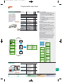
Accessories.
LRX 1V3 D024
LRX M00
Program backup memory
1
0.002
LRX C00
PC-LRD connecting cable, 1
1.5m long
0.060
LRX SW
Programming and
supervision software
(CD-ROM)
1
0.004
LRX 1V3 D024
Power supply unit,
1
100-240VAC/24VDC, 1.3A
0.188
LRX D00
User’s manual Italian
edition (paper)
1
0.397
LRX D01
User’s manual English
edition (paper)
1
0.397
LRX D02
User’s manual Spanish
edition (paper)
1
0.397
LRX D03
User’s manual French
edition (paper)
1
0.397
LRX C00
20-3
General characteristics
– The LRX 1V3 D024 power supply produces a
direct-current voltage to power the
base and
expansion modules in circumstances when 24VDC is
not available in the application. The power
supply can also be used to power eventual 24VDC
auxiliary circuits.
– The LRX M00 backup memory consents to save the
user’s program and to simply and quickly transfer it
to other
base modules.
– The LRE P00 expansion implements communications
using Modbus® protocol.
Programming
At any time and with extreme simplicity,
can be
set up and reprogrammed to satisfy new requirements
and improve the operation of a system.
Programming is simple and intuitive and can be done
directly on the relay keypad or by personal computer,
connected by LRX C00 interface and using the relative
LRX SW software.
Programming
with the keypad is quite simple and
straight forward, without particular programming
knowledge. There are 8 function keys on the relay front,
dedicated to on-board adjustment, control and
supervision of digital input and output status, analog
input values, time and date entry and the operation
status of the relay itself.
Programming sequences are shown on a backlit 4-line
12-character display.
When using a Personal Computer (PC), two common
language logics are available for programming: Function
Block Diagram (FBD) and LADDER (contact scheme).
Using the Simulator option, the user can control the
exactness of the implemented program in off-line
simulation, directly on the PC, before the ON-LINE
testing and the system setup.
Base unit inputs state
123456789ABC
RUN
MO 1 0 : 3 1
Base unit outputs state
Date and time LRD state
I/O STATUS
DATA
Expansion inputs state
KEY
123456789ABC
19 . 09 . 05
Expansion outputs state
Date
I/O STATUS
1123456789ABC
DEF
-
Memory, timer, counter,
RTC and analog
comparator state
PLC STATUS
KEY
ESC
TIME
A
A
A
A
1=1
2=0
3=2
4=6
.
.
.
.
2
0
4
5
5
0
0
9
Value of analog inputs
A
A
A
A
5=5
6=0
7=2
8=8
.
.
.
.
3
1
7
3
5
0
0
2
Value of analog inputs
7
MENU
LADDER ---------FBD -------------RUN -------------CLEAR PROG. --WRITE-----------READ -------------
1
2
3
4
5
6
SET--------------- 7
RTC SET --------- 8
ANALOG SET ---- 9
PASSWORD----- 10
LANGUAGE ----- 11
INITIAL --------- 12
1
I 1 -M1 - - - - ( Q 1
I 2Q 1 - m1 - - - - ( T 1
8
1
KEY
2
Analogs
STATUS 1
1
10 . 00
RUN
3
T1
9
PROG .
>YES
NO
10
CLEAR
4
11
>YES
NO
READ
6
Starter kits
>YES
NO
RTC SET V1 . 4
05 . 09 . 19
MO 1 3 : 4 3
A 1=GA
OFFS
A 2=GA
OFFS
A 3=GA
OFFS
A 4=GA
OFFS
I N
ET
I N
ET
I N
ET
I N
ET
:
:
:
:
:
:
:
:
01
+0
01
+0
01
+0
01
+0
P A S SWO R D
0000
0
0
0
0
0
0
0
0
x
PROG .
>YES
NO
WR I T E
5
I D SET
01
R EMO T E I \ O N
BACKL I GHT
x
M KEEP
√
I \ O N UMB E R : 0
I \ O A L A RM : √
C KEEP
x
ENGL I SH
FRANCA I S
ESPANOL
I TA L I ANO
DEUTCH
PORTUGUES
CH I NESE
I N I T I AL
12
>L ADDER
FBD
Starter kits.
LRDKIT 12R D024 LRD starter kit complete 1
with LRD12R D024 relay,
LRX SW software and
LRX C00 cable
LRDKIT 12R A024 LRD starter kit complete 1
with LRD12R A024 relay,
LRX SW software and
LRX C00 cable
LRDKIT 10R A240 LRD starter kit complete 1
with LRD10R A240 relay,
LRX SW software and
LRX C00 cable
Dimensions
page D-57
0.344
0.257
20
0.344
Wiring diagrams
page W-38
Technical characteristics
page TC-59