1
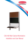
C36-430 Wall Cabinet Workstation Installation and User Manual Warnings IMPORTANT – Indicates a situation that does not present any hazard but is very important in maintaining a well functioning workstation. ATTENTION – Consult manual to avoid a potentially hazardous situation which may result in minor or moderate injury. o Contact the facility Engineer of Record for direction on mounting locations and methods prior to installing any wall tracks or equipment. o The shipping weight of this unit is 86 lbs (39.0 kg). Use proper lifting techniques to prevent injury. ELECTRICAL – Indicates an impending electrical hazard which, if not avoided, may result in personal injury, fire and/or death. o The supplied power cord is rated for medical use. Connecting the cord to an outlet that is not medical grade (indicated with a green dot) will not ensure grounding protection. (Locking cabinet only). o Power cord, USB extension, and workstation are for INDOOR use only. DO NOT OPERATE OUTDOORS. o Keep power cord away from water. DO NOT PLUG CORD INTO OUTLET IF WET. o DO NOT OPERATE PRODUCT IF WET. If the WORKSTATION becomes wet, unplug it immediately, wipe off any excess liquid, and allow it to dry before using again. o Inspect power cord before integration. DO NOT USE POWER CORD IF DAMAGED. o Fully insert power cord plug into outlet. DO NOT unplug by pulling on cord. DO NOT remove, bend or modify any metal prongs or pins of power cord. o DO NOT use excessive force to make mechanical or electrical connections. o DO NOT use an electrical extension cord with your workstation. o DO NOT use a flammable cleaner on the station as it can result in fire or explosion. Transport/Storage Care should be taken to transport and store this system within a temperature range of 32ºF to 90ºF (0ºC to 32ºC); Humidity 20% RH to 95% RH noncondensing. 2 Table of Contents Box Contents........................................................................... 5 Installation .............................................................................. 5 Parts Breakdown ................................................................ 6 Wall Cabinet Disassembly.................................................... 7 Fixed Height Wall Cabinet .................................................... 8 Height Adjustable Wall Cabinet........................................... 10 Wall Cabinet Reassembly .................................................. 12 Integration ............................................................................ 13 Technology Schematic....................................................... 13 Specifications ................................................................... 14 Technology Integration ...................................................... 15 Software Installation ............................................................ 20 Programmable Controller/Lock............................................ 26 Operation............................................................................... 32 Handle Release................................................................. 32 Auto-Retract ..................................................................... 32 Height Adjustment ............................................................ 33 Override Lock ................................................................... 33 Maintenance ......................................................................... 34 Service .................................................................................. 37 Warranty................................................................................ 37 REVISION HISTORY Revision Date Description of Changes A 06/2011 Initial Release B 10/2011 Change Mounting information p7, p9 C 2/2013 Change logos and references from RMS to Rubbermaid Healthcare Box Contents WORKSTATION x2 B A Taped inside of cabinet A Cabinet B CPU Security Key * C * C ** D ** D E te pla t em igh g T h He tin un wit Mo 6 430 bilitJOy3FE /PUFE SF T ta B 3 UT s C HSBN HI %JB H)FJ OE for Adju JO OTB PVOU r te fo pla ight Tem He ng ut nti witho ity u Mo 430 tabilTJO#MBDLBUJPOT s HSBN QQMJD 6 C3 AdjuBOE%JBBMMXBZ" Lo C3 30 99 GUIF 17 628 C364 LAR 30 NP 99 DI 17 629 C364 FB PUUP 99 IFC FEBU 17 631 99 : FBUU floor. PWJE 17 F ions EMJO the FFOQS UI JUI ruct FCPM from FC InstJHOUI 45" OTIBW ints.TCFTUX GUIF po FP s t"M plate DBUJP ing BMJHO tem MFMP ount BU VUTJE ha IP 4 m FUUI ns. POTP er it t the UIFT catio PDBUJ net aft of TF d lo FM bi PP stu IPM e ca t. t$I ility IF re th acke fac BSFU secu e br th FQ t to t1Sacke ng on br hu been JP SVDU BZ. *OTU )BMMX EFE us: et Sk abin ble 0C 43 ble ble justa C36 ble justa justa ht Ad for justa ht Ad ht Ad Heig ate ht Ad Heig Heig ct, mpl ig g, ct, Retra NFO DPN 3F He in g Te30H Lock Retra Auto ntinC36430LH Auto ing, Mou630 C36430HAR Lock 99 AR 17 632 C364 LH 30 99 IF 17 633 C364 PGU 99 17 634 UPN PME 99 CPU 17 UUIF or. OUIFC" from ns: MJOFB e flo "MJH 50 ctioFCPME m th POT plate F ru fro BUJ InstJHOUI 45" QQMJD the tem OBUUI of JP t"M plateXBZ"ttom UBMMBU tem BMM bo OT S) the SJ ts. SFGP in t'P e at . lin floor SFQB ing po Q nt e th LBOE mou BS ied t.entif id m ld Line be let Out catio Lo 6" mm 5" 4" 79. mm 148 16. 10" mm 9 mm 201 " 1.5 260 mm 38 417 net x6 F2 F1 #14 x 3" Pan Head G1 Flat Head Wood Screw G2 1/4 – 20 x 2.00 Phillips 94 9-82 or 8-85 Flo 1-88 call: 4" 28. mm 721 ition est net pos " 18.2 mm 1.5" mm " 13.8 mm 350 edg 423 ition net e of 590 6.5" mm 166 " (11.5 mm) 293 st pos (40.4 mm) at lowe r Floo cabi edg a dat 5" and areas (24.7 mm) er 629 pow ded ate sha Loc in lets out Flat Head Screw Pan Head Screw or Flo " (23.2 mm) " 11.7 mm 296 " (16.7 mm) 5" Bott 35.4mm 900 5" 1027 F2 1/4 – 20 x 2.00 Phillips 463 38 at high cabi x4 G2 x4 G3 ition ition st pos at lowe cabi e of x4 G1 x6 F3 pos est at high cabi net e of 5.9" mm 150 7.9" mm 200 r Floo 5& 1-" 5&. */( 6/5 .0 "%+ ()5 )&* "/% 9&% '* 8$ 1BSU *Note: For Fixed Height cabinets ONLY.. **Note: For Locking cabinets ONLY. 4 G ns: catio Lo e of om Height Adjustable Hardware Kit Wood Screw 06" 78. mm 3 edg 1" (74.3 mm) 1887 om G 198 176 5" Bott 19.7mm 502 Fixed Hardware Kit 5" 89. mm 9 227 ns: let a dat and areas er pow ded ate sha Loc in lets out edg (90.0 mm) 2288 1" Top 69.3mm 0 F flo " fro 45 shou Out 6" Top 85.0mm 1 216 6" Mounting Template or or flo m ns) " fro icatio 45 pl be Ap ld ay shou Hallw Line or for flo m fro (50" Cabinet Lock Override Key E F x6 F1 us JPOT GPS) et Sk SVDU EFE abin *OTU NFO 0C PN 43 3FD C36 for ty: ate abili net mpl just Cabi ct g Te t Ad dard ntin eigh Stan ing tract to Retra Mouout H 6430L Lockto Re g, Au C3 30 Au in with 627 64 AR ck /PU Wall Cleat F3 Wall Anchor G3 Wall Anchor Installation PARTS BREAKDOWN/RÉPARTITION DES PIÈCES/DETALLE DE LAS PIEZAS Release Handle Auto-Retract Solenoid* Keypad Monitor Bracket IR Module Override Lock** Keyboard Platform Mouse Pad Tinted Monitor Cover *Note: For cabinets with Auto-Retract ONLY. **Note: For Locking cabinets ONLY. 5 Installation WALL CABINET DISASSEMBLY (1) Remove two screws from top of 1 tinted monitor cover. (2) Removed tinted monitor cover. 2 1 x2 (1) Lift and (2) remove monitor bracket. 2 Note: For Fixed Height Wall Cabinet installation, go to page 7. Note: For Height Adjustable Wall Cabinet installation, go to page 9. 2 1 6 Installation FIXED HEIGHT WALL CABINET Note: Consult the Engineer of Record 1 ate mpl ght g Te Hei ntin with Mou 430 ability PUFE 3FE JO SF/ C36 st BNT JHIUTB for AdjuTBOE%PVOJBHSUJOH)F UJPO SVD EFE *OTU NFO DPN /PU ht , Heig Heig act, Tem H Heig king act, Retr ing 430LH Loc Retr, Auto Line e for inet 430 C36 ty: Sku Cab bili inet plat Tem Adjusta Cab ing ght Standard act Retract unt king Mo out Hei 430L Loc Retr, Auto C36 Auto with9627 C36430AR Locking F 1799628 C36430LAR PGUI I PN 1799629 C36430 FBD CPUU EBU UIF r. 1799631 s: FBU floo WJEF 179 tion EMJO the QSP IUIF ruc CPM from CFFO InstMJHOUIFe 45" OTIBWF ts. CFTUXJU GUIF poinHOT EFP t" plat BUJP g tem MPD ntin UBMJ VUTJ it has IPMF 4 mou UUIB s. OTP FTF tion BUJP after t the of TFUI loca MPD net IPP stud IPMFthe cabi ket. ity F t$ re facil SFUI secu brac the SFQB to t1 ket g on brac hun been UJPO Z. s: SVD Sku MMXB *OTU inet )B EFE Cab le stab le le NFO 430 PN stab Adju C36stableAdjustab 3FD Adju ht e forAdju ht ht Heig plat Auto king unt C36 Mo9630 C36430HARR Loc 1799632 C36430LHA F 1799633 C36430 PGUI PN 1799634 ME CPUU 179 FCPfrom UIF r. s: FBU floo OUI50" tion EMJO the "MJH e ruc CPM from BUJPOT plat F InstMJHOUIFe 45" QMJD the tem BUUI of JPO t" plat Z"Qom BMMBU tem MMXBbott JOTU S)B the GPS ts. t'P at r. QBSF g poin linefloo QSF the BOE mountin BSL d t. tifie iden 3F GPS ate mpl ght g Te Hei ntin with Mou 430 ability PUFE 3FE JO SF/ C36 st BNT JHIUTB for AdjuTBOE%PVOJBHSUJOH)F be 45" from let Out data r floo ) ions from licat 45" be App uld way sho Hall r for 89.5" mm 6" mm 148 1.5" mm Mo963 C36 HARR Loc 1799632 C36430LHA F 1799633 C36430 PGUI PN 1799634 ME CPUU 179 FCPfrom UIF r. s: FBU floo OUI50" tion EMJO the "MJH e ruc CPM from BUJPOT plat F InstMJHOUIFe 45" QMJD the tem BUUI of JPO t" plat Z"Qom BMMBU tem MMXBbott JOTU S)B the GPS ts. t'P at r. QBSF g poin linefloo QSF the BOE mountin BSL d t. tifie iden 38 and areas power shaded Locate in outlets 78.06" mm 1983 floo ns: atio Loc of Top position at highest cabinet edge at lowest of Top (74.31" mm) 28.4" mm 721 position 1.5" mm 38 at highest of 13.8" mm 350 (16.7" mm) 423 of Line Floor data and areas power shaded Locate in outlets r floo ) ions from licat 45" be App uld way sho Hall r for be 45" from Set line is measured from the floor to the black bold line as shown. Note 89.5" mm 2279 ns: atio 41716.4"mm 10" mm Loc 1.5" 260 mm let 38 Out data 6" mm 148 79.5" mm 2019 and areas power shaded Locate in outlets outlet locations and dimensions on 78.06" mm 1983 floo (23.2" mm) from 6.5" mm (50" ns: atio Loc at highest position let Out edge of cabinet 166 (11.5" mm) 293 Floor cabinet edge 5.9" mm Bottom (24.75" mm) 11.7" mm 296 position at lowest (40.45" mm) 629 18.2" mm 463 590 cabinet edge Bottom 35.45" mm 900 template (E) to mark drill hole locations. Sku Cab r floo uld sho Line Floor cabinet edge 69.31" mm 1887 1027 inet 430 , C36 L Auto with9627 C36430AR Locking F 1799628 C36430LAR PGUI I PN 1799629 C36430 FBD CPUU EBU UIF r. 1799631 s: FBU floo WJEF 179 tion EMJO the QSP IUIF ruc CPM from CFFO InstMJHOUIFe 45" OTIBWF ts. CFTUXJU GUIF poinHOT EFP t" plat BUJP g tem MPD ntin UBMJ VUTJ it has IPMF 4 mou UUIB s. OTP FTF tion BUJP after t the of TFUI loca MPD net IPP stud IPMF cabi t$ ity F re the ket. facil SFUI secu brac the SFQB to t1 ket g on brac hun been position (90.06" mm) 2288 1760 19.75" mm 502 3F C36 e forbility: inet plat Tem Adjusta Cab ing ght Standard act Retract king unt Mo out Hei 430 Loc Retr Auto Tem H Heig king act, Retr ing 430 Loc Retr, Auto unt0 C36430LH Auto king 79.5" mm 10" mm 2019 260 from (50" let Out 85.06" mm 2161 UJPO GPS SVD EFE *OTU NFO DPN /PU ht , Heig Heig act, 2279 ns: atio 41716.4"mm Loc Use the black portions of the mounting for ate t mpl eigh g Te t H ntin ithou ty Mou430 w abiliJO#MBDLJPOT st JBHSBNT QQMJDBU Z" E% C36 Adju s TBO )BMMXB UJPO Z. s: SVD Sku MMXB *OTU inet )B EFE Cab le stab le le NFO 430 PN stab Adju C36stableAdjustab 3FD Adju ht e forAdju ht ht Heig plat r floo uld sho Line regarding structural codes and utilities. E for ate t mpl eigh g Te t H ntin ithou ty Mou430 w abiliJO#MBDLJPOT st JBHSBNT QQMJDBU Z" E% C36 Adju s TBO )BMMXB Top 85.06" mm 150 position 2161 (90.06" mm) 2288 7.9" mm 200 at lowest of Top Floor cabinet edge 69.31" mm 1760 (74.31" mm) Floor mounting template. Mark and drill 6 28.4" mm 1887 721 position 1.5" mm 38 at highest A5& 5&.1- of 13.8" mm 350 of 18.2" mm Floor (23.2" mm) 6.5" mm 166 (11.5" mm) 293 Floor cabinet edge 5.9" mm Bottom (24.75" mm) 629 11.7" mm 423 position at lowest (40.45" mm) 1027 19.75" mm 502 296 (16.7" mm) Bottom 35.45" mm 900 463 590 cabinet edge 6/5*/( "%+.0 )&*()5 &%"/% 8$'*9 1BSU data and areas power shaded Locate in outlets 150 7.9" mm 200 Floor holes. A5& 5&.16/5*/( "%+.0 )&*()5 &%"/% 8$'*9 1BSU m fro ure s a r Me Floolate for p t Tem eigh See nting H u Mo o e sh Lin BUF NQM H5F OUJO .PV JYFE $' 8 BSU Note: For steel stud, all six wall anchors 2 (F3) must be installed before proceeding. Mount wall cleat (C) using pan head hardware provided. Note: Use part wall anchor (F3) and machine screw (F2) for steel stud installation. Use wood screws (F1) for wood studs. C x2 7 Installation FIXED HEIGHT WALL CABINET Hang wall cabinet (A) on wall cleat. 3 A Fold down keyboard tray half way to 4 access mounting holes. Insert four screws to secure the cabinet crossmembers. Note: Use machine screws (F2) for steel stud installation. Use wood screws (F1) for wood studs. x4 8 Installation HEIGHT ADJUSTABLE WALL CABINET Note: Consult the Engineer of Record 1 regarding structural codes and utilities. te pla t Tem Heigh ng unti with Mo 430 ility 36 stab C for Adju Use the red portions of the mounting IF PGU UPN CPU IF s: FBUUIF r. BUU tion EMJO the flooBMMBUJPO truc CPM Ins MJHOUIF 45" fromGPSJOTUts. e t" plat QSFQBSF g poin ntin tem BOE BSL d mou t. tifie iden template (E) to mark drill hole locations. ns: atio Loc let Out s: t at Cabine t Sku n positio le 430 le C36stable stab stableAdjustab ht Adju Adju ht te for pla ht AdjuHeig Heightact, Heig Tem Heig , ing H king act, Retr unt 430LH Loc Retr, Auto Mo9630 C36430HAR Auto king Loc 179 2 C36430 R 963 LHA 179 3 C36430 963 179 4 C36 963 179 uld Line be 45" t at Cabine from floo Set line is measured from floor to the te pla t Tem Heigh ng unti with Mo 430 ility b C36 justa r fo Ad n t positio highes ine Cab F PGUI PN CPUU F UIF s: FBU r. BUUI tion EMJO the flooBMMBUJPO truc CPM Ins MJHOUIF 45" fromGPSJOTUts. e t" plat QSFQBSF g poin ntin tem BOE BSL d mou t. tifie iden lowest ns: r atio let Loc Out red bold line. Note outlet locations and E dimensions on mounting template. sho n s: t Cabine t Sku t positio at highes ine Cab n positio le 430 le C36stable stab stableAdjustab ht Adju Adju ht te for pla ht AdjuHeig Heightact, Heig Tem Heig , ing H king act, Retr unt 430LH Loc Retr, Auto Mo9630 C36430HAR Auto king Loc 179 2 C36430 R 963 LHA 179 3 C36430 963 179 4 C36 963 179 t at Cabine Mark and drill 4 holes. lowest r uld Line e Adj be 45" from floo sho g Templat Mountin Height 2 WC2 Part #: 180202 m fro re u s a Me flooarte for t pl h Tem Heig See nting u Mo e Adj g Templat Mountin Height 2 WC2 Part #: 180202 M for Note: For steel stud installation, four 2 wall anchors (G3) must be installed before proceeding. Start screws in top locations only. DO NOT tighten. Note: Use wall anchor (G3) and machine screws (G2) for steel stud installation. Use wood screws (G1) for wood studs. x2 9 Installation HEIGHT ADJUSTABLE WALL CABINET Hang wall cabinet (A) on top two screws. 3 A x2 Fold down keyboard tray half way to 4 access mounting holes. Insert bottom two screws to secure the cabinet shuttle. Tighten all four screws. Note: Use machine screws (G2) for steel stud installation. Use wood screws (G1) for wood studs. x2 10 Installation WALL CABINET REASSEMBLY Replace monitor bracket. 1 Note: The user’s monitor needs to be attached to bracket, then hung in cabinet. See Integration section for details. (1) Replace tinted monitor cover. 2 (2) Replace two screws on top of tinted monitor cover. 1 2 x2 11 Integration TECHNOLOGY SCHEMATIC Power Cable Power Strip* Cable Grommet Video Cable Monitor Mouse CPU USB Extender Keyboard *Note: For Fixed Height cabinets ONLY. **Note: For Height Adjustable cabinets ONLY. 12 Power Cord** Integration SPECIFICATIONS Power Cord (Height Adjustable) Power Cord (Fixed Height) Power Strip 1 m Length, Medical Grade Right Angle NEMA Plug to C-13 plug, 120/240VAC, 6.3A, 50/60Hz. 2', Medical Grade Right Angle NEMA Plug (Illuminated for power indication) to C-13 plug. NEMA 5/15 outlets with inline fusing Power Indication (Powered Sku’s) Green LED Light mounted in the Monitor cabinet to provide power status. Power Indication (Base Model) Illuminated Right Angle NEMA Power Plug. USB (Control Board) USB A to Mini-B USB (TaskLight) USB A to Mini-B USB Peripherals 2 - USB A Male to USB A Female (Extension) VGA / DVI Cable Per Customer Technology Requirements Monitor Bracket 25 lbs (11.3 kg) max; VESA 75 mm & 100 mm Keyboard Platform Work Surface Accommodates 1.75" H x 18" W x 8" D (4.5 cm x 45.7 cm x 20.3 cm) USB keyboard 24.5" W x 9.4" D (62.2 cm x 23.9 cm) Mouse Area 7" W x 9.5" D (17.8 cm x 24.1 cm) Technology Cabinet Accommodates CPUs up to 12" W x 10" H x 2.8" D (30.5 cm x 25.4 cm x 7.1 cm) TECHNOLOGY INTEGRATION 1 2 3 1 x2 13 Integration USING 24" MONITOR (1) Remove screw from IR module. A1 (2) Remove IR module. OPTIONAL 2 1 (1) Replace IR module. A2 (2) Secure with two screws. OPTIONAL 2 1 14 x2 Integration TECHNOLOGY INTEGRATION (1) Attach monitor bracket to monitor. 2 (2) Place monitor inside wall cabinet. (3) Route power and video cables through cable grommet. 2 1 3 (1) Replace tinted monitor cover. 3 (2) Replace two screws on top of tinted monitor cover. 1 2 x2 15 Integration TECHNOLOGY INTEGRATION Place CPU into cabinet. Make necessary 4 electrical connections. Height Adjustable Cabinet – Connect 5 16 power cord to bottom of cabinet. If needed, connect optional CAT5e cable (not provided). Integration TECHNOLOGY INTEGRATION Place keyboard and mouse into 6 keyboard platform. Plug the USB connectors into the pre-wired USB extenders. Bundle excess cables and tuck under the worksurface. Note: Secure keyboard to drawer with velcro to avoid slipping. 17 Software Installation SOFTWARE SETUP Configuration of Software preferences: Installation (DO NOT plug USB cable in at this point): 1. Run LCDSecureIT - C36-430 Setup.msi setup file. 2. Once installation is complete plug in USB to an open port and wait for driver request. 3. The USB Driver is located within the files provided (at90usbxxx.inf) 4. After the USB drivers have been installed you can setup the software preferences. (see below) Shutdown the software Lower right-hand corner is a “Shutdown LCD SecureIT” button to completely close the software. If you close the window or press the “Send To Tray” button, it will be minimized to the system tray. Task Light Setup There are four options that are available when the keyboard is closed: • None (No action taken) • Immediate Blank Screen • Immediate Screen Saver (Select On resume, Password protect under screen saver options if user id and password is required) • Immediate lock computer screen You can adjust the duration of time the light will stay on at any given instance. (Default is 5 minutes). The password section is not applicable in this situation (Non-Locking Cabinets). Height Adjustability Setup (Height Adjustable models ONLY) There are three options for height adjustability: • Cabinet current limit- Allows administrators to define how much weight will be applied before the cabinet will stall. • Cabinet up / down Speed- Limits control how fast the cabinet moves up or down. • Cabinet Height Auto Return- Allows administrators to set the timer that will lock and return the cabinet to maximum height when the cabinet is left unattended. Note: The cabinet can be stopped during an auto-return by pressing anybutton on the keypad . 18 Software Installation SOFTWARE SETUP Locking Setup There are four options for locking: • Locking Timeout enables locking feature and time duration when cabinet will lock. • PIN Code Management allows administrators to import/export pin code list to/from the cabinet. • Network Pin Management allows remote pin code management. • Pin List manages pin codes on the cabinet. Note: See “Programmable Controller/Lock” section for more details. Auto Retraction (Auto-Retract models ONLY) There is one option for auto retraction: • Retraction timeout enables the auto retraction feature and time duration when the drawer will close. Status Information There are six options for status information: • If Drawer Is Closed is gray, no control board is present. If it is red, drawer is closed. If it is green, drawer is open. • If Drawer Is Locked is gray, no device is detected. If it is red, drawer is locked. If it is green, drawer is unlocked. • If User Presence Status is gray, no device is detected. If it is red, user is not present. If it is green, user is present. • If Tasklight Status is gray, no device is detected. If it is red, tasklight is off. If it is green, tasklight is on. • Version Information lists software, firmware, and hardware revision versions. • Enter Bootloader is a service utilty for use by trained service and IT technicians. 19 Programmable Controller/Lock PIN CODE LOCKING CABINET ONLY Green LED Red LED Numeric Buttons Clear Button Lock Button Raise Height Note: For Height Adjustable wall cabinets ONLY. Lower Height Note: For Height Adjustable wall cabinets ONLY. Programming Functions Locking Timeout • Lock the Tray: Check this box to enable Locking Feature. Uncheck to disable. • Minutes and Seconds: This feature determines how long after a user walks away from the cabinet before the cabinet locks. Dropdown box allows admins to select anywhere from 5 seconds to 15 minutes. 20 Programmable Controller/Lock PIN CODE LOCKING CABINET ONLY PIN Code Management • Copy PIN Codes from File to Device: This feature allows administrators to import pin code list into the cabinet. • Copy PIN Codes from Device to File: This features allows users to download all pins from this product (cabinet specific) to the local computer for backup. Network Pin Management • This is an accessory feature that allows remote pin code management. Check box to enable this feature. This feature will not work without the network pin code management software sold seperatly. Pin List • Digits in a Pin: Determines the length of pin codes (4 to 10 digits limitation). • Get List from Board: Populates a list in the pin list column from the control board. Pin list will show how many pins are stored on the control board below the list box. • Pin Addition: Pin entry is added here. User will add a pin defined around the number of digits defined in the “Digits in a Pin” section above. Once user has determined the pin code the “Add to List” Button will be pressed to populate to the pin list. • Remove Selected Button: In the pin list section, highlight a pin selected for removal, then click “Remove Selected” button to delete entry. • Commit Changes Button: Use this when all changes have been finalized. This will upload any pin entries/deletions to the control board. • Pin List and Pins Loaded: List of all pins stored on the control board and number of pins on control board. 21 Operation HANDLE RELEASE To close keyboard tray, pull release 1 handle. Note: The tray will close automatically when the release handle is pulled. se Clo AUTO-RETRACT 1 22 Auto-Retract Cabinet – If the IR module does not detect activity after the preset amount of time, the auto-retract feature will close keyboard tray. Operation ADJUSTING HEIGHT POSITION Height Adjustable Cabinet – (1) 1 Press up or down button on keypad to (2) adjust height position. 2 1 OVERRIDE LOCK Locking Cabinet – If keypad becomes 1 inoperable, the override lock can be used to open the keyboard platform. D 23 Maintenance DO NOT use the workstation if pieces are missing or the unit is damaged. In these cases, immediately contact Rubbermaid Customer Service for more information: 1-888-859-8294. Cables: Always keep the cables neatly organized and be sure to route cables away from moving components with • Remove pen and dry erase marker stains with a soft cloth and 91% isopropyl alcohol. • Remove iodine stains with a soft cloth and any cleaners suggested above. DO NOT use the following chemicals to clean your workstation: acetone, mineral wire ties or spirits, abrasive cleansers, paint thinner or any other harsh cable clips. or toxic chemicals. Electric Cables: Periodically inspect power cord and plug WOOD PANEL CARE to ensure plug is not bent and cable is not frayed. Harsh, abrasive and undiluted cleaning products may cause damage to Deco Lam and the contact adhesive. CLEANING Pine Sol and Simple Green are cleaners that have been CAUTION: Because of the close proximity of approved for use on Deco Lam. A 30-1 ratio of water to electrical power and equipment, flammable cleaner is highly advised. Recommend water and a clean cleaners should never be used on the workstation. • Verify that your workstation is unplugged from the wall outlet before cleaning. • Allow your workstation to dry completely before plugging the power cord into a wall outlet. • When cleaning the workstation, wipe surface with a damp cloth and thoroughly dry. • NEVER cover the workstation or its components with liquid or allow liquids to flow into the workstation. • NEVER use steel wool or other abrasive material as these could damage the surface finish. • Before using any cleaner on the workstation, first test on a small area to ensure that the surface is not harmed. • These guidelines cannot guarantee infection control. The hospital’s Infection Control Administrator should be consulted regarding cleaning procedures and schedules. • Clean plastic components with diluted, non-abrasive solutions. Suggested cleaners are water, soap, diluted bleach and alcohol solutions. 24 towel as a cleaning alternative to homeowners. Troubleshooting Problem Solution Software does not show connectivity to task light Check USB communications cable. Solenoid does not fire Pin code entry problems Unplug and reconnect USB cable to establish communications Check that automatic detection in software is enabled and verify connectivity. Check firmware version - update firmware if necessary. Check membrane connections. Press clear and lock button at the same time. Check that retract the tray box is checked. Check retraction time out time. Check connections. PCheck pin code list in software. Check that lock the tray box is checked. Check that the digits in the pin box and the number of digits being entered is equal. Cabinet lock does not function Check connections. Press lock button and re-enter pin code, then press lock again. Check that lock the tray box is checked. Check timing of lock cycle. Keypad does not function Check connections. Look for LED status indicators Unplug and reconnect membrane cable. Linear actuator does not function Check connections. Check for power to control board. Check that there is not excessive weight applied to the cabinet or obstructions in the way of travel. Check that speed limitations settings in software. Check membrane connector. IR sensor does not operate Check connections. Look for LED status indicators. Adjust gain control on IR sensor to adjust output. Software does not operate Restart computer. Uninstall/reinstall software. Check firmware version of task light/control board. 25 Troubleshooting (continued) Problem Solution Top door needs Open the top door and locate the 2 hinges on the right side. To adjust the door adjustment for alignment up or down use the inside screw of the hinges. To adjust the door right or left use the outside screw on the hinges. No Power Keypad lock not working Lift is not working Unit does not function Power supply does not turn on Software does not show connectivity to control board 26 Check cable connections to power supply in the top cabinet. Use override key on the bottom left side. Ensure power cables are connected and power is available. Check power supply. Check wall outlet for power. Check USB communications cable. Check connectivity/communications with software. Check power input cable. Check wall outlet for power. Check fuses at cabinet power inlet. Check USB communications cable. Check power supply. Check that the control board is not in bootloader mode - remove power from control board, wait 60 seconds and reconnect power. Check firmware version - update firmware if necessary. Service SERVICE REQUEST Please visit our website at: www.rubbermaidhealthcare.com/service to file a request for parts. SERVICE LEVEL COMMITMENT Rubbermaid Healthcare is committed to providing best-in-class service. This document details our standard warranty and instructions on how to request service using our customer support system. Warranty LIMITED WARRANTY FOR WALL MOUNTED WORKSTATIONS Rubbermaid Healthcare is pleased to offer a five-year warranty on durable components and a two-year warranty on electronic components. If during the warranty period this Rubbermaid Healthcare product proves defective in materials or workmanship under normal use by the original purchaser, please contact Rubbermaid Healthcare technical support at www. rubbermaidHealthcare.com/service (please be sure to complete all information, including product serial number, description of the issue, and full contact information). Rubbermaid Healthcare will determine, at its sole discretion, how to best address your warranty issue, which may include sending you a replacement part covered under warranty or for sale. Rubbermaid Healthcare reserves the right to require proof-of-purchase prior to honoring any warranty request. This warranty does not cover product abuse, modification, failure to adhere to product instructions, or improper operation/misuse. Rubbermaid Healthcare SHALL NOT BE LIABLE FOR ANY CONSEQUENTIAL OR INCIDENTAL DAMAGES WHATSOEVER. Some states do not allow the exclusion or limitation of incidental or consequential damages, so the above limitation or exclusion may not apply to you. This warranty gives you specific legal rights and you may also have other rights which vary from state to state or country to country. Service Details Consumable components are not covered under warranty and include: • Cable grommet • Back panel of cabinet • Door lock and key • Pull latch for bottom door All other standard components will be replaced under the applicable warranty following a filed service request. If the service request is received prior to 10 am EST, replacement parts will ship next business day. Requests filed after 10 am EST will be fulfilled with parts shipped in 2 business days. All replacement parts will ship via ground carrier. *The above terms for replacement parts applies to facilities located in the United States. All other customers should contact the appropriate reseller for the terms of part replacement. 27 1-888-859-8294 www.RubbermaidHealthcare.com 2/2013 Part # 1813426 WC2 USER MANUAL REV. C © Rubbermaid Healhcare Huntersville, NC 28078