1
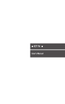
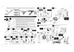
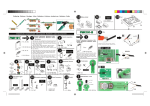
57mm 7-SEGMENT DIGITAL CLOCK
with e
ture display
ra
e
p
m
te
&
clock
re
Large 57mm
unique featu
Total solder points: 263
Difficulty level: beginner 1
2
3
4
xtra
5 ⌧ advanced
K8089
ILLUSTRATED ASSEMBLY MANUAL
H8089IP-1
Features & specifications
Features :
12/24h clock system
min temp readout:
• celsius: -20°C
• fahrenheit: -4°F
max temp readout:
• celsius: 70°C
• fahrenheit: 158°F
auto toggle function
easy time setting
easy wall mounting
back-up battery
automatic frequency detection
unique extra feature: auto toggle between time/temp and scrolling sign
'OPEN' or 'CLOSED'
Specifications
•
•
•
•
•
power supply: 12VAC (e.g. PS1205AC)
power consumption: 250mA max. (incl. temp. sensor*)
backup battery: 3V (CR2032)
power consumption on backup battery: +/-1mA
dimensions: 230x74x32mm / 9 x 2.9 x 1.25"
* optional : temperature sensor K8067 or VM132
3
Assembly hints
1. Assembly (Skipping this can lead to troubles ! )
Ok, so we have your attention. These hints will help you to make this project
successful. Read them carefully.
1.1 Make sure you have the right tools:
• A good quality soldering iron (25-40W) with a
small tip.
• Wipe it often on a wet sponge or cloth, to keep it clean; then apply solder to
the tip, to give it a wet look. This is called ‘thinning’ and will protect
the tip, and enables you to make good connections. When solder
rolls off the tip, it needs cleaning.
• Thin raisin-core solder. Do not use any flux or grease.
• A diagonal cutter to trim excess wires. To avoid injury when cutting
excess leads, hold the lead so they cannot fly towards the eyes.
• Needle nose pliers, for bending leads, or to hold
components in place.
• Small blade and Phillips screwdrivers. A basic range
is fine.
For some projects, a basic multi-meter is required, or might
be handy
0.0
00
1.2 Assembly Hints :
⇒ Make sure the skill level matches your experience, to avoid disappointments.
⇒ Follow the instructions carefully. Read and understand the entire step before
you perform each operation.
⇒ Perform the assembly in the correct order as stated in this manual
⇒ Position all parts on the PCB (Printed Circuit Board) as shown on the
drawings.
⇒ Values on the circuit diagram are subject to changes.
⇒ Values in this assembly guide are correct*
4
Assembly hints
⇒ Use the check-boxes to mark your progress.
⇒ Please read the included information on safety and customer service
* Typographical inaccuracies excluded. Always look for possible last minute
manual updates, indicated as ‘NOTE’ on a separate leaflet.
1.3 Soldering Hints :
1- Mount the component against the PCB
surface and carefully solder the leads
2- Make sure the solder joints are cone-shaped
and shiny
3- Trim excess leads as close as possible to the
solder joint
AXIAL COMPONENTS ARE TAPED IN
THE CORRECT MOUNTING SEQUENCE !
REMOVE THEM FROM THE TAPE ONE AT
A TIME !
5
Construction
Hint: if you want the mount the clock against a wall, you can use the unstuffed
PCB as a template to mark the drill holes.
1. Resistors.
3. Zener diodes (check the polarity)
ZD1 : 4V3
ZD2 : 4V3
ZD2 : 4V3
ZD3 : 4V3
R...
Hint: resistors can be soldered at
component side of the board.
R1
R2
R3
R4
R5
: 100K
: 10
: 22K
: 22K
: 240
(1 - 0 - 4 - B)
(1 - 0 - 0 - B)
(2 - 2 - 3 - B)
(2 - 2 - 3 - B)
(2 - 4 - 0 - 0 - 1)
R6 ... R37 : 220 (2 - 2 - 1 - B) !
R38 : 1K
(1 - 0 - 2 - B)
CATHODE
4. IC sockets. Watch the position
of the notch!
IC1
IC2
IC3
IC4
IC5
:
:
:
:
:
14p
16p
16p
16p
16p
1
IC...
5. Capacitors
c...
R39 ... R42 : 10K (1 - 0 - 3 - B) !
R44 : 220
R45 : 2K2
R46 : 10K
ZD...
(2 - 2 - 1 - B)
(2 - 2 - 2 - B)
(1 - 0 - 3 - B)
C1 ... C11 : 100nF
2. Diodes (check the polarity)
D ...
CATHODE
(104)
C13 : 100nF (104)
6. Switches
Hint: mount a screw connector if remote
selection is needed, see step 12.
D1
D2
D3
D4
D5
D6
D7
6
:
:
:
:
:
:
:
1N4007
1N4007
1N4007
1N4007
BAT85
BAT85
1N4148
SW1 : Open / closed
SW1.
Construction
7. Transistors
12. Terminal blocks
T1 : BC547
T2 : BC547
T1
8. Voltage regulator
VR1 : UA7808
SK1 : 2p power 12VAC
SK2 : 3p Temp. sensor
! If remote selection is needed :
SW1 : 2p Open/closed
13. Electrolytic capacitor.
Watch the polarity !
C...
C12 : 470µF / 25V
-
VR2 : UA78L05
VR...
14. Heat sink
Make sure that the heat sink does
not touch C12 !
9. Battery holder
E1 : CR2032 (3V)
10. Push buttons
SW2 :
SW3 :
SW4 :
Sign on/off
Hours +
Minutes +
11. Pinheaders
2pins:
SK3 : 12h/24h
SK4 : °C/°F
SK5 : Clock/clock+temp
3pins:
hh:mm / hh.mm
15. IC's. Watch the position of the
notch!
IC1 : VK8089
(programmed PIC16F630-I/P)
IC2
IC3
IC4
IC5
:
:
:
:
74HC595
74HC595
74HC595
74HC595
7
Construction
MOUNT THESE COMPONENTS ON THE PCB SOLDERSIDE, SOLDER
THEM ON THE COMPONENTS SIDE
1. Tulip pin headers
DY1
DY2
DY3
DY4
:
:
:
:
2 x 5pins
2 x 5pins
2 x 5pins
2 x 5pins
t
Cu
ins
5p
x
8
ins
5p
SOLDER SIDE
4
DY
3
DY
2
DY
1
DY
8
construction
2. Digit displays
DY1
DY2
DY3
DY4
ATTENTION: mount the displays so that the
dot is mounted towards the push button.
Side with push buttons
1
DY
2
DY
3
DY
4
DY
Make sure that all displays are
correctly mounted !
3. Assembly of the enclosure
1 Mount the leds, watch the polarity.
CATHODE
display
display
9
Construction
4. Test and connection
1. Power supply:
Supply 9-12VAC to the inputs marked '12VAC'.
Make sure supply can deliver 300mA
Make sure to use an AC power supply. If you supply a DC voltage, the
accuracy of the clock will be 5% worst case.
2. Back-up battery:
Insert a 3V CR2032 battery in the battery holder. If power
fails, unit will retain the clock. Display will remain blank.
Note: Accuracy when running on backup battery: 5%
worst case. Consumption: +/- 1mA
CHECK IF THE CLOCK IS WORKING CORRECTLY (see page 13)
5. Optional temperature sensor
If you have ordered an additional temperature sensor K8067
or VM132 then you can let the temperature automatic toggle
with the time and sign.
Optional temperature sensor
Connect the terminals marked GND, V+ and IN to the corresponding terminals of
the temperature sensor. As this is a current loop sensor, you can run several
meters of wire between the sensor and the clock.
10
Optional sensor
K8067/VM132
K8089
Adjusting the temperature sensor (Skip this if there is no temp. sensor connected.
In this case, make sure jumper is set to 'clock').
Put a reliable thermometer next to the temperature sensor and leave it there for a
while. Press and hold 'Min'-button and apply power to the unit. The unit will
display the temperature only (Make sure back-up battery is removed)
Adjust the multiturn pot. (RV1) on the temperature sensor until the displayed
temperature matches the temperature indicated by the thermometer.
Remove and re-apply power to restart the clock. If necessary, insert backup
battery.
6. Jumper settings
Use the shunt to select for choosing the display,
temperature en time readout.
Jumper placed
Jumper removed
Mode
1
2
3
Display
Temp
Time
clock
°F
12h
clock / temperature
°C
24h
11
Jumper setting
jumper, to select how seconds are indicated.
hh.mm
hh:mm
hh mm
7. Assembly in enclosure
1 Assemble the 4 individual housing together.
2 Turn the PCB around with the displays on
top, place the enclosure on the PCB.
12
Use
8. Use
Minute 'Min'
Hour 'Hrs'
Mode
Message select
1. Use as thermometer only (no clock):
Hold 'Min'-button and apply power. Unit will display
temperature only. If required, you can permanently
bridge the 'Min'-button.
2. Setting the time:
Select 12h or 24h readout by means of the jumper.
Press 'Hrs' to set the hours, press 'Min' to set minutes.
At release, seconds will start from zero.
3. Turning on/off the 'OPEN'/'CLOSED' display.
Press 'Mode' to toggle between 'ON' (show sign) and
'OFF' (do not show sign).
Selecting 'OPEN'/'CLOSED'. The slide switch allows you
to display either 'OPEN' or 'CLOSED'. You can remove
the slide switch and replace it by the supplied screw
connector.
By doing so you can easily put an optional switch in a remote location, to
select between 'OPEN' or 'CLOSED'.
4. Extra feature:
Hold 'Hrs'-button and apply power (make sure to remove backup battery first).
Now, the unit displays the approx. AC grid frequency. If required, you can
permanently bridge the 'Hrs'-button.
13
PCB
PCB
14
15
R6
R7
R8
R9
R10
R11
R12
R14
R15
R16
R17
R18
R19
R20
R21
R22
R23
R24
R25
R26
R27
R28
R30
R31
R32
R33
R34
R35
R36
Schematic diagram
Schematic diagram
VELLEMAN KIT NV
Legen Heirweg 33
9890 Gavere
Belgium Europe
Info ?: http://www.velleman.be
Modifications and typographical errors reserved
© Velleman Kit nv
H8089IP - 2009 (rev.1)
5 410329 403188