1
Total solder points: 775
Difficulty level:
beginner 1o 2o 3o 4o 5þ advanced
Multifunctional clock display
Features :
R
R
R
R
R
R
R
R
R
R
R
R
R
R
K8009
6 x 36mm high digits.
Time, date & temperature indication, selectable with toggle option.
1 sec. resolution chronometer with lap function.
Count down function to a specific date.
Scoreboard function (two players or teams, count up to 199).
Random generator from 00 to 99.
2 digit dice.
Hour chime option.
Counter display.
Relay output for temperature control or time alarm.
US or Europe display option: time, date, degrees Celsius or Fahrenheit.
Wireless remote control for all functions (wired remote possible).
Optional enclosure type B8009.
Optional extra remote type K6706A, K6706B or K6706G.
Specifications :
—
—
—
—
—
—
—
—
Fixed 433.92 MHz transmitter frequency, as required by law.
Key chain remote control included.
Temperature indication from -20 to +70 ºC (resolution 1º).
Temperature indication from 0 to +150 ºF (resolution 2º).
Memory backup option: 9V battery or rechargeable battery T331
Relay output: 1A / 24V max.
Supply: 12VDC/300mA power supply (adapter type PS1203).
Dimensions : 252 x 80mm (without enclosure).
Modifications reserved
ILLUSTRATED ASSEMBLY MANUAL
H8009IP-3
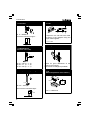
Assembly hints
1. Assembly (Skipping this can lead to troubles ! )
Ok, so we have your attention. These hints will help you to make this project
successful. Read them carefully.
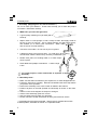
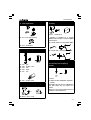
1.1 Make sure you have the right tools:
• A good quality soldering iron (25-40W) with a
small tip.
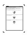
• Wipe it often on a wet sponge or cloth, to keep it clean; then apply solder to
the tip, to give it a wet look. This is called ‘thinning’ and will protect the tip,
and enables you to make good connections. When solder
rolls off the tip, it needs cleaning.
• Thin raisin-core solder. Do not use any flux or grease.
• A diagonal cutter to trim excess wires. To avoid injury when cutting
excess leads, hold the lead so they cannot fly towards the eyes.
• Needle nose pliers, for bending leads, or to hold components in place.
• Small blade and phillips screwdrivers. A basic range
is fine.
For some projects, a basic multi-meter is required, or might
be handy
0.0
00
1.2 Assembly Hints :
⇒ Make sure the skill level matches your experience, to avoid disappointments.
⇒ Follow the instructions carefully. Read and understand the entire step before
you perform each operation.
⇒ Perform the assembly in the correct order as stated in this manual
⇒ Position all parts on the PCB (Printed Circuit Board) as shown on the drawings.
⇒ Values on the circuit diagram are subject to changes.
⇒ Values in this assembly guide are correct*
⇒ Use the check-boxes to mark your progress.
⇒ Please read the included information on safety and customer service
* Typographical inaccuracies excluded. Always look for possible last minute
manual updates, indicated as ‘NOTE’ on a separate leaflet.
2
Assembly hints
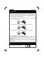
1.3 Soldering Hints :
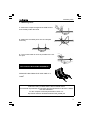
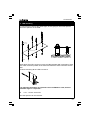
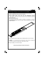
1- Mount the component against the PCB surface
and carefully solder the leads
2- Make sure the solder joints are cone-shaped
and shiny
3- Trim excess leads as close as possible to the solder joint
AXIAL COMPONENTS ARE TAPED IN
THE CORRECT MOUNTING SEQUENCE !
REMOVE THEM FROM THE TAPE ONE AT A
TIME !
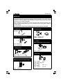
Velleman hereby certifies that the device K8009 meets
the essential requirements and all other relevant stipulations of directive 1999/5/
EG and 1995/5/EC.
For the complete conformity declaration check out :
http://www.velleman.be/downloads/doC/CE_K8009.pdf
3
4
P
E
Verde
Blu
Viola
Grigio
Bianco
5
6
7
8
9
S
Brun
Svart
Blå
Grön
Kulta
Dourado Oro
Grå
Guld
Silver
Valkoinen Vit
B Oro
Blanco
Harmaa
Hopea
Branco
Sininen
Vihreä
Morado Purppura Lila
Azul
Cinzento Gris
Violeta
Azul
Verde
Naran- Oranssi Orange
jado
Amarelo Amarillo Keltainen Gul
Verde
DK
4K7= ( 4 - 7 - 0 - 1 - 1 )
1%
N
Rød
Brun
Sort
Guld
Sølv
Hvid
Grå
Violet
Blå
Grøn
Gul
Guldl
Sølv
Hvidt
Grå
Violet
Blå
Grønn
Gul
Orange Orange
Rød
Brun
Sort
FÄRG FARVE- FARGESCHEMA KODE
KODE
Punainen Röd
Ruskea
Musta
VÄRI
KOODI
SF
A Argento Prateado Plata
4
Aranciato
Giallo
3
Rojo
Rosso
2
Encarnado
Laranja
Marrone Castanho Marrón
Negro
1
Preto
Nero
0
C CODICE CODIGO CODIGO
O COLORE
DE
DE
D
CORES COLORE
E
S
I
4K7= ( 4 - 7 - 2 - B )
5%
GB
F
NL
Gold
Silber
Weiss
Grau
Violet
Blau
Grün
Gelb
Orange
Rot
Braun
Gold
Silver
White
Grey
Purple
Blue
Green
Yellow
Orange
Red
Brown
Or
Argent
Blanc
Gris
Violet
Bleu
Vert
Jaune
Orange
Rouge
Brun
2
1
4
Goud
Zilver
Wit
Grijs
B
A
9
8
Paars 7
Blauw 6
Groen 5
Geel
Oranje 3
Rood
Bruin
FARB COLOUR CODIFI- KLEUR C
KODE
CODE CATION KODE O
D
DES
E
COULEURS
Schwarz Black
Noir
Zwart 0
D
COLOR= 2… 5
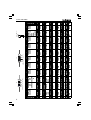
Color code table
Construction
IMPORTANT
First the remote control PCB is assembled, P6706A:
The remote control can be build for wireless remote operation or for “wired” remote
operation (no need for battery in the transmitter). In case of a wired remote, only a few
components are mounted, see further.
Before mounting the components on the PCB, first check that the PCB fits in the
housing. Watch the small notch next to LD1. Should it not fit, then grind the edges of
the PCB carefully.
Mount only the components marked with “#” if wired remote is wanted.
1. Jumperwire
5. Push buttons
q J1 #
2. Diodes (Check the polarity)
q SW1 : KRS0611 #
q SW2 : KRS0611 #
D...
CATHODE
6. IC socket
(Watch the position of the notch)
q D1 : BAT85 #
q D2 : BAT85 #
1
IC...
3. 1/4W Resistors
q IC1 : 18p #
R...
q R4 : 33K (3 - 3 - 3 - B)
q R5 : 100K (1 - 0 - 4 - B) #
7. Capacitors
C...
4. SAW resonator
(Watch the position of the notch)
X...
q X1 : SAW433
q
q
q
q
q
q
C1 : 100pF
(101)
C2 : 1pF small type !
C3 : 56pF
C4 : 4,7pF
(4p7, 4.7)
C5 : 56pF
C6 : 470pF
(471) #
5
Construction
8. Transistor
11. Coil
5mm
q T1 : MPSH10
Check the minimum height ! :
7mm
A simple air core coil has to be made
as shown in the diagram using the
jumper lead supplied
q L1: 1 turn
12. Battery contacts
9. 1/4W Resistors
(check the color code)
R...
q R1 : 33K (3 - 3 - 3)
q R2 : 47 (4 - 7 - 0)
q R3 : 220 (2 - 2 - 1)
Check for good attachment of the
solder to the contacts.
Mount them as straight as possible!
10. LED (check the polarity)
13. IC
(Watch the position of the notch !)
COLOR= 2...5
1
LD...
PIN 1
CATHODE
q LD1 : 3mm (2)
Mount at the indicated height :
18mm
11mm
6
q IC1 : UM3758 #
IC...
Construction
14. Create your code
Your own individual code can be set for a transmitter/clock combination. There is
a row of nine code pads that are the closest to IC1, only one code connection is
used. The code can be set by linking the code pad to a neighbouring "-" pad or "+"
pad by using a jumper lead. JC1 and JC2 are located on the main PCB P8009.
There are 3 different combinations possible:
1. JC1 and JC2 are not mounted on the main PCB, then do not mount code
jumpers on the transmitter.
2. JC1 is mounted on the main PCB, Mount a jumper like in the drawing:
3. JC2 is mounted on the main PCB, Mount a jumper like in the drawing:
In case of a “wired” remote, continue the assembly.
In case of a wireless remote, the transmitter PCB can be placed in his enclosure.
Fit a new 12V battery type V23GA or GP23A. Check the polarity which is shown
in the enclosure.
REMARK: If the buttons do not “click”, please check the position of the PCB. It
is also possible that the first time, you have to press firmly the button cap before
they work properly.
15. Sticker
Affix the supplied sticker to the housing.
Velleman
433,92 MHz
SRFCE
7
Construction
Assembly of the main PCB P8009 :
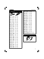
1. Jumperwires
q
q
q
q
q
q
q
q
q
q
q
q
q
q
q
q
q
q
q
q
q
q
q
q
q
q
q
q
q
q
q
q
q
q
q
q
q
8
J1
J2
J3
J4
J5
J6
J7
J8
J9
J10
J11
J12
J13
J14
J15
J16
J17
J18
J19
J20
J21
J22
J23
J24
J25
J26
J27
J28
J29
J30
J31
J32
J33
J34
J35
J36
J37
q
q
q
q
q
q
q
q
q
q
J38
J39
J40
J41
J42
J43
J44
J45
J46
J47
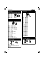
2. Diodes (Check the polarity)
D...
CATHODE
q
q
q
q
q
q
q
q
q
D1 : 1N4007
D2 : 1N4148
D3 : 1N4148
D4 : BAT85
D5 : BAT85
D6 : 1N4148
D7 : 1N4148
D8 : 1N4148
D9 : 1N4148
3. Zener diode (Check the polarity)
ZD...
CATHODE
q
q
q
q
q
q
ZD1 : 6V2
ZD2 : 3V3
ZD3 : 4V7
ZD4 : 4V3
ZD5 : 5V1
ZD6 : 9V1
Construction
4. 1/4W Resistors
R...
q
q
q
q
q
q
q
q
q
q
q
q
q
q
q
q
q
q
q
q
q
q
q
q
q
q
q
q
q
q
q
q
q
q
q
q
q
q
q
q
R1 : 100K
R2 : 270
R3 : 270
R4 : 4K7
R5 : 270
R6 : 5K6
R7 : 2K7
R8 : 2K2
R9 : 10K
R10 : 100K
R11 : 10K
R12 : 4K7
R13 : 10K
R14 : 100K
R15 : 47K
R16 : 2K2
R17 : 150
R18 : 100K
R19 : 4K7
R20 : 10K
R21 : 270
R22 : 100K
R23 : 100K
R24 : 270
R25 : 270
R26 : 100K
R27 : 100K
R28 : 100K
R29 : 100K
R30 : 100K
R31 : 100K
R32 : 4K7
R33 : 10K
R34 : 270
R35 : 270
R36 : 100K
R37 : 4K7
R38 : 10K
R39 : 100K
R40 : 100K
(1 - 0 - 4)
(2 - 7 - 1)
(2 - 7 - 1)
(4 - 7 - 2)
(2 - 7 - 1)
(5 - 6 - 2)
(2 - 7 - 2)
(2 - 2 - 2)
(1 - 0 - 3)
(1 - 0 - 4)
(1 - 0 - 3)
(4 - 7 - 2)
(1 - 0 - 3)
(1 - 0 - 4)
(4 - 7 - 3)
(2 - 2 - 2)
(1 - 5 - 1)
(1 - 0 - 4)
(4 - 7 - 2)
(1 - 0 - 3)
(2 - 7 - 1)
(1 - 0 - 4)
(1 - 0 - 4)
(2 - 7 - 1)
(2 - 7 - 1)
(1 - 0 - 4)
(1 - 0 - 4)
(1 - 0 - 4)
(1 - 0 - 4)
(1 - 0 - 4)
(1 - 0 - 4)
(4 - 7 - 2)
(1 - 0 - 3)
(2 - 7 - 1)
(2 - 7 - 1)
(1 - 0 - 4)
(4 - 7 - 2)
(1 - 0 - 3)
(1 - 0 - 4)
(1 - 0 - 4)
q
q
q
q
q
q
q
q
q
q
q
q
q
q
q
q
q
q
q
q
q
q
q
q
q
q
q
q
R41 : 100K (1 - 0 - 4)
R42 : 10K
(1 - 0 - 3)
R43 : 10K
(1 - 0 - 3)
R44: 10K
(1 - 0 - 3)
R45 : 10K
(1 - 0 - 3)
R46 : 10K
(1 - 0 - 3)
R47 : 4K7
(4 - 7 - 2)
R48 : 100K (1 - 0 - 4)
R49 : 560
(5 - 6 - 1)
R50 : 100K (1 - 0 - 4)
R51 : 2K2
(2 - 2 - 2)
R52 : 4K7
(4 - 7 - 2)
R53 : 2K2
(2 - 2 - 2)
R54 : 2K2
(2 - 2 - 2)
R55 : 1K
(1 - 0 - 2)
R56 : 1K
(1 - 0 - 2)
R57 : 6M8
(6 - 8 - 5)
R58 : 6K8
(6 - 8 - 2)
R59 : 18K
(1 - 8 - 3)
R60 : 270
(2 - 7 - 1)
R61 : 33K
(3 - 3 - 3)
R62 : 18K
(1 - 8 - 3)
R63 : 10K
(1 - 0 - 3)
R64 : 10K
(1 - 0 - 3)
R65 : 5K6
(5 - 6 - 2)
R66 : 2K7
(2 - 7 - 2)
R67 : 100K/1% (1 - 0 - 0 - 3)
R68 : 270K/1% (2 - 7 - 0 - 3)
5. Axial coil
L2
q L1 : 1µH (1 - 0 - B)
9
Construction
6. IC socket
(Watch the position of the notch)
q
q
q
q
q
q
IC1 : 8p
IC2 : 18p
IC3 : 18p
IC4 : 18p
IC5 : 16p
IC6 : 8p
1
IC...
7. Capacitors
C...
q
q
q
q
q
q
q
q
q
q
q
q
q
q
q
q
9. Transistors
C1 : 470pF
C2 : 470pF
C3 : 100nF
C4 : 100nF
C5 : 100nF
C6 : 2pF
C7 : 12pF
C8 : 330pF
C9 : 330pF
C10 : 22pF
C11 : 330pF
C12 : 1pF
C13 : 2pF
C14 : 82pF
C15 : 330pF
C16 : 100nF
(471)
(471)
(104, µ1)
(104, µ1)
(104, µ1)
(2.2, 2p2)
(331)
(331)
(331)
(331)
(104, µ1)
q
q
q
q
q
q
q
q
q
q
q
q
q
q
q
q
q
q
q
q
q
q
q
q
T1 : BC547C
T2 : BC547C
T3 : BC547C
T4 : BC547C
T5 : BC547C
T6 : BC547C
T7 : BC547C
T8 : BC547C
T9 : BC547C
T10 : BC547C
T11 : BC547C
T12 : BC547C
T13 : BC547C
T14 : BC547C
T15 : BC547C
T16 : BC547C
T17 : BC557
T18 : BC557
T19 : BC557
T20 : BC557
T21 : BC557
T22 : BC557
T23 : BC557
T24 : BF199
10. Voltage regulator
8. Quartz crystal
X...
VR...
q VR1 : 78L05
q X1 : 4.194304
Fix the quartz crystal by means of a
jumpwire.
10
Construction
11. Trim capacitors
14. Relay
CV...
RY...
q RY1 : VR3D121C
q CV1 :Trim 22p (Green)
A selection is possible for a normal
closed contact output, or a normal open
contact output :
For normal closed, mount jumper JNC:
q CV2 : TRIM 5p5
12. Electrolytic capacitors
For normal open, mount jumper JNO:
C...
q
q
q
q
q
C17 : 1µF
C18 : 100µF / 16V
C19 : 1µF
C20 : 10µF
C21 : 1µF
q C22 : 470µF / 25V
13. Buzzer (check the polarity)
+
BUZ...
15. PCB pin. Mount only if you
have access to a frequency
counter.
q GND
q Testpin for time calibration 15.625ms
(64Hz)
This testpin can be used to calibrate the
clock (see chapt. 22) by means of a
counter.
Adjust CV1 for a period measurement of
15.625ms or 64Hz frequency.
q BUZ1 : SV4 / 12-S
11
Conctruction
16. Temperature sensor
SENS...
q
SENS: LM335
Make the connections longer when using an enclosure like our optional enclosure
type B8009 (use blank jumpwires)
12
Construction
17. LED mounting
To mount all the LED’s at the same hight, we are going to use some spacers.
Mount the spacers on the PCB:
15mm M3 BOLT
10mm SPACER
COMPONENT SIDE UP
M3 NUT
Mount about five LED’s, then turn over the PCB and solder ONE connection of each
LED. Now correct the position of the LED’s and solder the other connection of each
LED.
Continue mounting all the LED’s as above.
It is important that when our optional enclosure B8009 is used, that the
maximum hight is respected !
q
LD1… LD132: 3mm LED.
Now the spacers can be removed.
13
Construction
18. Resistor trimmer
20. IC’s
(Watch the position of the notch !)
1
RV...
PIN 1
IC...
q RV1 : 500E (470)
19. Connectors
q
q
q
q
q
q
SK... +
SW
-
q SK1 : DJ005
SK...
q SK2 : BATCON
q SK3 : SCREW02
If a 9V block battery is used for the
memory backup, then the following
snap can be connected:
RED
BLACK
Check the polarity !
14
IC1 : CA3160
IC2 : VK8009 (PIC16C715)
IC3 : UM3758
IC4 : UM3758
IC5 : CD4017
IC6 : LM258
Connection
21. Connecting the wired remote control
Only three wires are used to connect the transmitter with the display.
q Connect one wire between the + from the display and the + of the transmitter
(connection next to R5)
q Connect one wire between the - from the display and the - of the transmitter
(connection next to C5)
q Connect one wire between C on the display and the connection at R1 on the
transmitter (see drawing).
P8009
C
-
C
R1
P6706
C
SK4
-
+
+
Before mounting the transmitter PCB in the enclosure, make a small slot in the
bottom enclosure to pass the wires.
CUT OUT
Now the transmitter can be placed in his enclosure.
G REMARK: If the buttons do not “click”, please check the position of the PCB.
It is also possible that the first time, you have to press firmly the button cap
before they work properly.
15
Test & adjustment
22. Test and adjustment
First we will test if the display works properly:
• Connect a 12VDC / 300mA adapter (check the polarity and the connector
type) to the display. The display should indicate the time 00:00:00
(HH:MM:SS) and the (HH) should blink.
Next step is adjusting the displays- receiver to the transmitter. (skip this
step if a wired transmitter is used).
1
2
>Remote control button code.
• Hold the transmitter about one meter (one yard) away from the display.
• Press button 1 on the transmitter, the LED on the transmitter should blink
rapidly.
• Now adjust the trimmer capacitor CV2 (RECEIVER ADJUST) on the display
using the supplied plastic tuning screwdriver, until the receiver LED (REC),
blinks at the same rate as the transmitter.
• If a maximum range between transmitter - display is wanted, then it is advisable to repeat the above adjustment with the transmitter at about 10m (10
yard).
• If the adjustment is OK, then the HH of the display should increase each time
button 1 is pressed.
G
Remark : Hold the display away from large metal objects.
Next step is to calibrate the temperature indication :
• Disconnect the power supply from the display.
• Reconnect the power supply to the display.
• Put a known good thermometer next to the display temperature sensor.
• Press repeatedly button 2 on the transmitter until the display shows dAtE
blinking.
• Now press button 1 until rEGIOn is blinking.
• Next press button 2, Eu will blink. Use button 1 to choose between Eu
(Europe) or uS (USA) display format for time, date and temperature.
• Confirm your choice by pressing button 2.
• Now press the left button until dEGrEE is displayed and confirm with button 2.
• Now adjust the trim potentiometer RV1 (TEMP. CALIBRATION) until the displayed temperature corresponds with the “reference” thermometer.
G
16
Repeat the above adjustment after the display is warmed up for a few hours.
Test & adjustment
Next step is to calibrate the clock time base
The processor has an internal oscillator that is used to run the clock.
By means of CV1(TIME CALIBRATION), it is possible to adjust the oscillator
frequency if the clock does not run correctly.
1. Start by setting the trim capacitor in his center (50% overlap) position:
50%
2. should the clock run too fast, then turn the capacitor more in the maximum
(100% overlap) direction:
100%
3. should the clock run too slow, then turn the capacitor more in the minimum
(no overlap) direction:
0%
17
Mounting
23. Mounting the display into the optional enclosure B8009
• Remove the display window and the side panels from the enclosure.
• Slide the PCB into the lower slot of the enclosure.
• At the left hand side two holes must be made in the small cover, one for the
power supply plug*, and one for the temperature sensor.
* Alternatively a hole can be made at the back of the enclosure to pass the
power supply plug.
• Mount the two side panels.
• At the right hand side there is space for a battery, a 9V battery or a 3.6V rechargeable battery type T331 can be used. Connect the battery to the appropriate connector.
After connecting the power supply plug, the display window can be mounted.
G REMARK :
It is important that the temperature sensor body is outside the
enclosure otherwise the temperature readout will be faulty.
G Keep the display out of direct sunlight.
See the user manual for further instructions.
18
PCB
&
DIAGRAMS
19
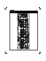
PCB
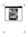
24. Transmitter PCB
20
T1
17
J2
16
3
R9
4
2 LD1
J8
J7 37
38
R11
VR1
24 23 22
25
ZD1
C3
R17
GND
D4
T3
61
R19
62
57
D5
T19
R20
49
T4
R32
81
J25
J24
R33
69
D6
68 67 66
T23
+ RED
J35 104
J36
1
BLACK 91 90
89
IC5
92
P8009'2
9V BATTERY
J44
R42
R43
R44
R45
111
C20 C19
D8
112J43
ZD2
BUZ1
T7
J45
110 LD132
R40
T8
NC
NO
R41
JNC
VELLEMAN
TESTPIN FOR TIME CALIBRATION
D3
C21 15.625ms
D2
J18
47 46 45
8
R1 J17 60
48
C4
R36
R15
COIL1
RY1
COIL2
C
C
-
OUT
+SK2
5
J3
6
T17
R10
T2
R12
26
J12
82
70
J26 71
-
1
R59
JC1
JC2
C6
C7
R34
R35
R24
R25
R21
C2
R13
R8
R2
R3
SENS
ZD6
SK4
C
R66
R4
1
R39
D9
C16
R38
R46
113 OUT R54
T6
T5
125
93
T21
C17
T22
105
126
R47
114
ZD5
J9 27
J30
J19 50
J37 94
J40
R37
T20
+
ZD4
LD87 106
129
65 64
83
42T18
86
115
109 108
39
127
J22
J5
18
101
J46
J23
J6
J41
J13
J31
13
128
21 20 19
41 40
107
63
85 84
LD43
130
78
34
J34
122
14
95
J20
J27
72
J38
J10
28
51 79
116
7
58
IC6
35
52
123
R63
29
102
J28
J4
J21
J11
J39
R60
J14
73
96
117
8
R64
56 55
LD88
100 99 98
120 119
LD44
12 11
J47
36
124
R61
J32
15
103
R65
118
R62
97
59
9
74
30
53
80
IC4 121
IC3
C14
J15
R51
10
54
b
77
76
75
33 32 31
R5
C11
R22
C10
CV1
R26
e
L1
T9
R23
R6
R68
R27
C15
X1
c
CV2
R28
+ C12
R67
R48
R50
C1
J29
IC2
RECEIVER ADJUST
R7
R29
IC1
C8
C9
LD131
9
C5
RV1
R4
J33
ADDRESS SELECTION: MOUNT JC1 OR JC2 OR LEFT OPEN
R30
TIME CALIBRATION
J16
T10 T11 T12 T13 T14 T15 T16
TEMP. CALIBRATION
J1
R1
C22
D1
D7
J42
JNO
T24
SK1
ZD3
R52
REC
R53
+
R55
R56
1
R3
R57
-
C18
SK3
C13
3V6
R58
SW
1
1
6
R1
1
+
12VDC/200mA
PCB
Display PCB
21
R14
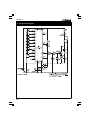
Diagrams
25. Transmitter diagram
22
82p
4K7
R52
330p
330p
6K8
R58
C15
1u
C17
ZD6
1uH
L1
1p
4V3
ZD4
1K
R56
C18
+VR
A1
1
5V1
1K
ZD5
+VR
1/2 LM258
R55
3
2
6
5
IC3
6
5
OUT
A12
A11
A10
A9
A8
A7
A6
A5
A4
A3
17
14 15
VSS
MODE
12
11
10
9
8
7
UM3758-120A
13
3
4
100K
IC4
6
5
4
8 7
A2
-SK2
+SK2
D5 BAT85
100n
C3
RED 3mm
REC
LD131
2K2
R53
+SK4
cSK4
-SK4
+VR
3V6
E1
+VR
R8
2K2
100K
22p
TIME CALIBRATION
CV1
R67
5K6
LM335
R6
500
RV1 SENS
2K7
+V
R7
+V
OUT
A12
A11
A10
A9
A8
A7
A6
A5
A4
A3
+V
7
5
6
NC
NC
NC
NC
NC
NC
NC
NC
NC
10K
R13
2p
C6
X1
AN3
RA4
RA2
C2
12p
C7
OSC2
OSC1
470p
C1
470p
4.194304MHz
270K
R68
JC1
JC2
NC
CA3160
2 IC1
4
3
14 15
VSS
MODE
17
12
11
10
9
NC
NC
NC
7
UM3758-120A
13
3
4
8
330p
C9
R50
OSC
NC
NC
NC
NC
NC
NC
TEMP. CALIBRATION
R48
OSC
2
A2
NC
Rx IN
VDD
A1
16 18
1
2
A2
100K
D2
1N4148
1/2 LM258
10K
R64
10K
R63
6V2
ZD1
C16
100n
2p
C13
6M8
R57
100u
A1,A2 = IC6 (LM258/RV4558)
RECEIVER ADJUST
C12 +VR
CV2
18K
R62
+VR
9V1
R16
2K2
R17
C4
1u
C21
D4
15
16
2
3
1
4
5
VSS
IC2
PIC16C71
MCLR
100n
11
7
8
13
10
6
9
12
17
18
VDD
14
D6
1N4148
3V3
ZD2
BC557
T23
E2
9V BATTERY
+RED
100K
CO
DO8
DO0
10K
R44
RST
100K
RB5 R27
100K
RB1 R26
100K
RB2 R22
100K
RB7 R29
100K
RB4 R28
100K
RB0 R30
100K
RB3 R23
100K
RB6 R14
NC
NC
NC
RA0
10K
R45
CLK
13
CE
12
9
3
15
10
6
1
2
4
5
560
560
R5
560
R34
560
R25
560
R35
560
R3
560
R21
560
BC547C
T13
R24
BC547C
T12
BC547C
T11
BC547C
T16
BC547C
T14
BC547C
T15
BC547C
T10
BC547C
dp
g
f
e
d
c
b
a
100K
DO4 R39
100K
DO5 R36
GND
15.625ms
100K
DO1 R31
100K
DO2 R18
100K
DO6 R10
R2
VSS
T9
8
IC5
CD4017
14
R9
LD1
10K
LD22
10K
LD25
CLL30331
LD47
LD16
LD35
LD41
LD40
CLL30331
LD43
CLL30331
LD42
CLL30331
CLL30331
LD21
CLL30331
LD20
CLL30331
CLL30331
LD19
CLL30331
CLL30331
LD37
CLL30331
LD38
CLL30331
LD39
CLL30331
LD18
LD17
CLL30331
CLL30331
LD36
CLL30331
CLL30331
LD15
CLL30331
LD14
LD34
CLL30331
CLL30331
LD13
CLL30331
CLL30331
LD31
CLL30331
LD32
CLL30331
LD33
CLL30331
LD12
LD11
CLL30331
LD29
CLL30331
LD30
CLL30331
LD8
CLL30331
LD9
CLL30331
CLL30331
CLL30331
LD10
CLL30331
CLL30331
LD28
CLL30331
LD26
CLL30331
LD27
LD7
CLL30331
LD5
CLL30331
LD6
LD48
LD51
LD54
LD57
LD60
LD73
CLL30331
LD74
CLL30331
LD64
CLL30331
LD44
CLL30331
LD72
LD75
LD78
CLL30331
LD82
LD81
LD87
CLL30331
CLL30331
LD86
CLL30331
LD85
CLL30331
LD84
CLL30331
CLL30331
LD80
CLL30331
LD79
CLL30331
CLL30331
LD77
CLL30331
LD76
CLL30331
CLL30331
LD83
LD65
LD69
CLL30331
CLL30331
CLL30331
LD63
LD70
CLL30331
LD71
LD89
10K
R38
LD92
LD95
LD98
LD101
LD104
LD107
LD88
CLL30331
CLL30331
LD109
CLL30331
LD108
CLL30331
CLL30331
LD106
CLL30331
LD105
CLL30331
CLL30331
LD103
CLL30331
LD102
CLL30331
CLL30331
LD100
CLL30331
LD99
CLL30331
CLL30331
LD97
CLL30331
LD96
CLL30331
CLL30331
LD94
CLL30331
LD93
CLL30331
CLL30331
LD91
CLL30331
LD90
T8
LD113
LD116
LD119
LD122
LD125
CLL30331
LD130
LD128
CLL30331
LD129
CLL30331
CLL30331
LD127
CLL30331
LD126
CLL30331
CLL30331
LD124
CLL30331
LD123
CLL30331
CLL30331
LD121
CLL30331
LD120
CLL30331
CLL30331
LD118
CLL30331
LD117
CLL30331
CLL30331
LD115
CLL30331
LD114
CLL30331
CLL30331
LD112
CLL30331
LD111
BC557
T22
+VL
LD110
10K
R46
CLL30331
4K7
R47
BC557
T21
C
SK3
VR3D121C
NO
RELAY OUTPUT
NC
BC547C
+VL
R41
RY1
+VL
100K
CLL30331
4K7
R37
BC557
T20
+VL
LD66
CLL30331
CLL30331
LD68
CLL30331
LD67
LD62
CLL30331
10K
R33
10K
R43
1N4148
OUT D9
2K2
R54
C20
10u
LD132
CLL30331
1N4148
D7
CLL30331
4K7
R32
BC557
CLL30331
CLL30331
LD61
CLL30331
CLL30331
LD59
CLL30331
LD58
CLL30331
CLL30331
LD56
CLL30331
LD55
CLL30331
CLL30331
LD53
CLL30331
LD52
CLL30331
CLL30331
LD50
CLL30331
LD49
CLL30331
CLL30331
CLL30331
LD24
CLL30331
CLL30331
LD46
LD23
LD3
LD45
10K
R40
SV4-12S
BUZ1
T7
BC547C
+VL
100K
T19
+VL
R20
CLL30331
4K7
10K
R42
C19
1u
R19
BC557
T18
D8
1N4148
+VL
R11
CLL30331
4K7
R12
BC557
T17
+VL
LD2
LD4
CLL30331
BC547C
T6
BC547C
T5
BC547C
T4
BC547C
T3
BC547C
T2
BC547C
T1
4K7
R4
CLL30331
-BLACK
R49 VDD
DO9 DO7
560
16 11
6 DO3 R1
100n C5
7
RA1
BAT85
+V
270
D3
1N4148
VR1
I
O
UA78L05
R15
47K
ADDRESS SELECTION: MOUNT JC1 OR JC2 OR LEFT OPEN
2K7
R66
BF199
T24
5p
L2
18K
470u
C22
+VL
VDD
ZD3 Rx IN
A1
16 18
1
2K2
R51
330p
C11
22p
C10
C14
4V7
C8
5K6
R65
33K
R61
R60
1N4007
R59 270
DJ-005
SW
12VDC/200mA INPUT
D1
SK1 +
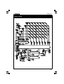
Diagrams
Display diagram
23
VELLEMAN COMPONENTS NV
Legen Heirweg 33
9890 Gavere
Belgium Europe
Info & support: www.velleman.be
Modifications and typographical errors reserved
© Velleman Components NV
H8009IP - 2002 - ED3