1
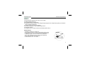
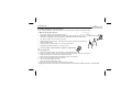
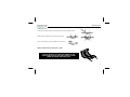
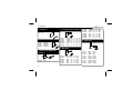
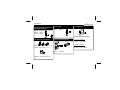
Total solder points: 144 Difficulty level: beginner 1 2 3 4 5 advanced DC CONTROLLED DIMMER K8064 ment adjuste . s s e tn h ag e brig Simple ns of a DC volt a e by m ISE NO SSED PRE G TO SUP RDIN 5 O 1 ACC EN550 ILLUSTRATED ASSEMBLY MANUAL H8064IP-1 This dimmer is a practical circuit enabling you to adjust the brightness of a lamp or a group of lamps via an adjustable direct tension. This tension can have various sources e.g. an analogue output of our K8000, K8055, VM110, ... The dimmer can use both resistive loads (e.g. light bulb) and inductive loads (halogen lighting). Use a conventional (wirewound) transformer for low voltage halogen lighting (12V). Most electronic transformers are not compatible with this dimmer. For safety reasons, the adjustment voltage has been optically isolated from the supply voltage. Applications: stage lighting, domotics, etc... 2 Features & Specifications Features: Simple brightness adjustment by means of a DC voltage. Optically isolated adjust input. Pre-set adjustment for full brightness. Suitable for incandescent lamps, mains voltage halogen lighting and low voltage halogen lighting in combination with a conventional transformer. "Soft start" feature to ensure lamp longevity. Transformer protection in case of defective light sources. LED status indication. Compatible with our computer interface cards: K8000, K8055, VM110. Specifications: Adjustment voltage: 0 to 12Vdc max. Max. adjustment current: 2.25mA at adjustment voltage of 12V. Suppression of radio & TV interference according to EN55015. Operating voltage: 110-125V or 220-240V AC (50/60Hz). Max. load: 750W/230V or 375W/110V, 0-98% adjustable. Max. phase shift with inductive load: 30°. PCB dimensions: 90 x 75 x 40mm 3 Assembly hints 1. Assembly (Skipping this can lead to troubles ! ) Ok, so we have your attention. These hints will help you to make this project successful. Read them carefully. 1.1 Make sure you have the right tools: A good quality soldering iron (25-40W) with a small tip. Wipe it often on a wet sponge or cloth, to keep it clean; then apply solder to the tip, to give it a wet look. This is called ‘thinning’ and will protect the tip, and enables you to make good connections. When solder rolls off the tip, it needs cleaning. Thin raisin-core solder. Do not use any flux or grease. A diagonal cutter to trim excess wires. To avoid injury when cutting excess leads, hold the lead so they cannot fly towards the eyes. Needle nose pliers, for bending leads, or to hold components in place. Small blade and Phillips screwdrivers. A basic range is fine. 0.0 00 For some projects, a basic multi-meter is required, or might be handy 1.2 Assembly Hints : Make sure the skill level matches your experience, to avoid disappointments. Follow the instructions carefully. Read and understand the entire step before you perform each operation. Perform the assembly in the correct order as stated in this manual Position all parts on the PCB (Printed Circuit Board) as shown on the drawings. Values on the circuit diagram are subject to changes. Values in this assembly guide are correct* Use the check-boxes to mark your progress. Please read the included information on safety and customer service * Typographical inaccuracies excluded. Always look for possible last minute manual updates, indicated as ‘NOTE’ on a separate leaflet. 4 Assembly hints 1.3 Soldering Hints : 1- Mount the component against the PCB surface and carefully solder the leads 2- Make sure the solder joints are cone-shaped and shiny 3- Trim excess leads as close as possible to the solder joint REMOVE THEM FROM THE TAPE ONE AT A TIME ! DO NOT BLINDLY FOLLOW THE ORDER OF THE COMPONENTS ONTO THE TAPE. ALWAYS CHECK THEIR VALUE ON THE PARTS LIST! 5 Construction 1. Jumpers 4. 1/2w (Metal film) resistors R... J : 3x 2. Diodes. Watch the polarity ! D1 D2 D3 D4 : : : : 1N4148 1N4007 1N4148 1N4148 CATHODE D... R1 R2 R9 R10 R13 R17 : : : : : : 470K 100K 470K 100K 220 1M (4 - 7 - 4 - B - 9) (1 - 0 - 4 - B - 9) (4 - 7 - 4 - B - 9) (1 - 0 - 4 - B - 9) (2 - 2 - 1 - B - 9) (1 - 0 - 5 - B - 9) R11 R12 R14 R15 R16 R18 R19 : : : : : : : 470K 100K 4K7 4K7 4K7 33K 1K (4 - 7 - 4 - B) (1 - 0 - 4 - B) (4 - 7 - 2 - B) (4 - 7 - 2 - B) (4 - 7 - 2 - B) (3 - 3 - 3 - B) (1 - 0 - 2 - B) 6. Capacitors. C... 5. Resistors R... 3. Zenerdiode. Watch the polarity ! CATHODE ZD1 : 4V7 6 ZD... R3 R4 R5 R6 R7 R8 : : : : : : 1K5 1K5 390 4K7 4K7 4K7 (1 - 5 - 2 - B) (1 - 5 - 2 - B) (3 - 9 - 1 - B) (4 - 7 - 2 - B) (4 - 7 - 2 - B) (4 - 7 - 2 - B) C1 : C2 : C3 : C4 : C5 : C6 : C7 : C8 : C14 : 10nF 15pF 15pF 10nF 100nF 100nF 100nF 100nF 10nF (103) (15) (15) (103) (104) (104) (104) (104) (103) Construction 7. LEDs. Watch the polarity! 10. Resistor trimmer 13. Voltage regulator RV1 COLOR= 2...5 LD1 : 3mm Green LD2 : 3mm Red RV1 : 220K (250K) RV2 : 2M2 (2M5) VR1 : UA78L05 VR... LD... 11. 1W Resistor CATHODE R... 14. Capacitor. 8. Zenerdiode. Watch the polarity ! 5mm +/-5mm CATHODE ZD... ZD2 : 12V 9. IC socket. Watch the position of the notch! R20 : 220 (2 - 2 - 1 - B) 12. Transistors C12 : 100nF / 250Vac T1 : BC547 T2 : BC547 IC1 : 14p IC2 : 6p 7 Construction 15. Electrolytic Capacitors. Watch the polarity ! C9 : 10µF C10 : 100µF C11 : 220µF 17. Crystal X1 : 10MHz 19. Capacitor. X... C... Choose operating voltage : 16. Terminal connectors 18. Fuse + Fuseholder For 110 - 125VAC : C13 : 1µF / 250V F... SK1 : 2p (AC power) Pitch 7,5mm SK2 : 2p (Load) Pitch 7,5mm C13 : 0,47µF / 630V F1 : 4A SLOW SK3 : 2p (Analog IN) Pitch 5mm 8 For 220 - 240VAC : Construction 20. Coil 22. IC’s. Watch the position of the notch! L... IC1 : VK8064 (programmed PIC16F676) IC2 : TIL111 or 4N27 L1 : 1,5mH / 4A 21. Triac. mm 10mm 3 BOLT BOLT M3 LOCK WASHER IMPORTANT : PUT AN EXTRA THICK TIN COATING ON THE ALREADY THINNED PCB TRACKS! M3 NUT TR1 : TIC225M or eq. 9 Test & adjustment procedure 23. TEST and ADJUSTMENT PROCEDURE: Once the assembly completed, you still need to set the dimmer for your particular application. Use an adjustment voltage of 0 to 5 (or to 12V max). You can now wire the print according to the connection diagram (see page 13). Connect the supply voltage for a brief instant. Upon activation of the device, LD1(green LED) & LD2(red LED) briefly flash together during the self-test. LD1 will flash briefly if there are no problems: 1 x in case of a mains frequency of 50Hz and 2 x for 60Hz. There is a problem if the red LED remains lit (see error messages). Turn RV1 fully counterclockwise and turn RV2 fully clockwise Set the control voltage to 0 VDC Apply AC power. Adjust RV1 (minimum level) until LD1 (green) starts flashing rapidly Trim RV1 just below the bulb ignition threshold Set your max. control voltage e.g. 10 VDC Adjust RV2 (maximum level) until LD1 (green) burns steadily The circuit is now ready for use 10 Test & adjustment procedure Remark: In order to stretch bulb life, we recommend you adjust the minimum setting in such a way that the bulb filament remains heated. This is particularly useful for theatre lighting applications BONUS Function: Activate the bonus function by placing a jumper wire over JP1 and JP2. With the bonus function, the operation of the circuit is exactly the opposite of the operation under normal circumstances: the lamp burns at maximum intensity at an adjustment voltage of 0V and extinguishes at the max. adjustment voltage that has been set beforehand. LED indications in case of normal operation: LD1 (green LED): Flashes once every 5 seconds when the unit is in standby mode (lamp off). Flashes slowly (2x/sec) when the lamp is burning, but not when it's burning at max. intensity. Remains lit when the lighting burns at max. intensity. 11 Test & adjustment procedure LED indications in case of error: When the CPU detects an error, LD1 (green) lights up continuously, whereas LD2 (red) repeatedly emits a series of flashes. We advise you to briefly interrupt the supply voltage and evaluate the situation. Flashes LD2 1 Error 3 Time out in the positive alternation of the mains voltage Time out in the negative alternation of the mains voltage Triac triggering time out 4 Phase shift is too great 2 Possible cause error in voltage zero-crossing circuit (T1, ...) error in voltage zero-crossing circuit (T1, ...) - Triac defective ? Light source defective ? T2 defective ? Load doesn't conform to specifications ? Load behaves too inductively ? No load connected ? No load on transformer (because of defective lamp ?) Load not conform ? The “MON” connection on the PCB is only used by our technical department for purposes of repair and diagnosis. 12 Connection example 24. CONNECTION EXAMPLE 0 - 10V DEVICE + - For example : K8000, K8055 (VM110), Dimmer pack, ... L N MAINS N L’ INCANDESCENT LAMP 13 PCB 25. PCB layout. L N N L’ 14 Diagram 26. Diagram N L N L’ 15 VELLEMAN NV Legen Heirweg 33, B-9890 GAVERE Belgium (Europe) Modifications and typographical errors reserved © Velleman nv. H8064IP’1 - 2014 (rev.1) 5 410329 324551