1
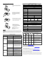
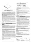
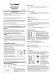
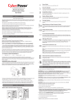
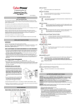
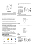
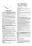
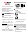
BASIC OPERATION
FRONT PANEL AND REAR PANEL DESCRIPTION
eu.cyberpowersystems.com
Utility Tower Series UPS
UP350TE/UP500TE/UP500E/UP750E
User Manual
POWER
ON
K01-U350E0A-01
POWER
ON
USING
BATTERY
USING
BATTERY
SAFETY WARNINGS
(SAVE THESE INSTRUCTIONS)
This manual contains important safety instructions. Please read and follow all instructions carefully
during installation and operation of the unit. Read this manual thoroughly before attempting to
unpack, install, or operate your UPS.
◆ Power
This equipment can be operated by any individuals with no previous training.
UP350TE/UP500TE
Switch
UP500E/UP750E
Press the power button to turn the UPS ON or OFF.
The socket-outlet shall be installed near the equipment and easily accessible.
During the installation of this equipment it should be assured that the sum of the leakage currents of
the UPS and the connected loads does not exceed 3.5mA.
Attention, hazardous through electric shock. Also with disconnection of this unit from the mains,
hazardous voltage still may be accessible through supply from battery. The battery supply should be
therefore disconnected in the plus and minus pole at the quick connectors of the battery when
maintenance or service work inside the UPS is necessary.
◆ Power
On Indicator
This LED is illuminated when the utility condition is normal and the UPS outlets are
providing “clean power”, free of surges and spikes.
◆ Using
Battery Indicator
This illuminates during utility failure, indicating that the battery is supplying power to
the battery-power supplied outlets.
Do not dispose of batteries in a fire, the battery may explode.
Do not open or mutilate the battery or batteries, released electrolyte is harmful to the skin and eyes.
◆
Battery Backup and Surge Protection Outlets
INSTALLING YOUR UPS SYSTEM
The UPS provides battery powered and surge protected
outlets for connected equipment to insure temporary
uninterrupted operation during a power failure and against
surges and spikes.
UNPACKING
Inspect the UPS upon receipt. The box should contain the following:
®
UPS Unit; PowerPanel Software Disk¯1; Serial Interface Cable (DB-9)¯1; Telephone Cable¯1;
®
IEC-IEC Power Cord¯2; User Manual; PowerPanel Software User Manual.
◆
Surge Protection Outlets
HOW TO DETERMINE THE POWER REQUIREMENTS OF YOUR
EQUIPMENT
The UPS provides surge protected only outlet for connected
equipments against surges and spikes.
1. Insure that the equipment plugged into the battery power-supplied outlets does not exceed the
UPS unit’s rated capacity (350VA/210W for UP350TE, 500VA/300W for UP500TE, 500VA/325W
for UP500E, 750VA/450W for UP750E). If rated unit capacities are exceeded, an overload
condition may occur and cause the UPS unit to shut down or the circuit breaker to trip.
2. If the power requirements of your equipment are listed in units other than Volt-Amps (VA), convert
Watts (W) or Amps (A) into VA by doing the calculations below. Note: The below equation only
calculates the maximum amount of VA that the equipment can use, not what is typically used by
the equipment at any one time. Users should expect usage requirements to be approximately 60%
of below value.
◆ Serial
Port to PC
This port allows connection and communication from the DB-9 serial on the computer
®
to the UPS unit. The UPS communicates its status to the PowerPanel software. This
interface is also compatible with the UPS service provided by Windows 98, Windows
ME, Windows NT, Windows 2000, Windows XP, Windows Server 2003.
◆ Ethernet
(RJ-45) Network Protection Ports
TO ESTIMATE POWER REQUIREMENTS
1.
Watts (W) x 2.0 =
VA or
Amps (A) x 230 =
VA
These ports are the protection for your computer network cable.
2. Add the totals up for all pieces of equipment and multiply this total by 0.6 to calculate actual
requirements. There are many factors that can affect the amount of power that your computer
system will require. The total load that you will be placing on the battery-powered outlets should
not exceed 80% of the unit’s capacity.
HARDWARE INSTALLATION GUIDE
1. Connect the equipment to your UPS outlets. The IEC-IEC power cords coming with the unit are
used to connect your computer and monitor to the UPS. Items such as copiers, laser printers,
vacuums, space heaters, or other large electrical devices should not be connected to the UPS.
Please make sure that the total loads of your equipments are less than the maximum total power
load of your UPS.
2. Use your computer power cord to connect the UPS to a wall outlet. Please avoid using extension
cords and adapter plugs. (To maintain optimal battery charge, leave the UPS plugged in at all
times.)
3. Press the UPS power button to turn it on. The “Power On” indicator will be illuminated in “Green”.
4. Install your software and accessories. To use the software, simply connect the enclosed serial
interface cable to the serial port on the UPS and an open serial port on the computer.
BATTERY REPLACEMENT AND STORAGE
CAUTION! Read and follow the IMPORTANT SAFETY INSTRUCTIONS before servicing the battery.
Service the battery under the supervision of personnel knowledgeable of batteries and their
precautions. Keep unauthorized personnel away from batteries. If you have questions, contact
your dealer or call the number in this manual for information on battery replacement.
CAUTION! Use only the specified type of battery. See your dealer for replacement batteries.
CAUTION! The battery may present the risk of electrical shock. Do not dispose of batteries in a
fire, as it may explode. Follow all local ordinances regarding proper disposal of batteries.
CAUTION! Do not open or mutilate the batteries. Release electrolyte is harmful to the skin and eyes
and may be toxic.
CAUTION! A battery can present a high risk of short circuit current and electrical shock. Take the
following precautions before replacing the battery:
1. Remove all watches, rings or other metal objects.
2. Only use tools with insulated handles.
3. DO NOT lay tools or other metal parts on top of battery or any battery terminals.
4. Determine if the battery is inadvertently grounded. If inadvertently grounded, remove source of
ground. CONTACT WITH A GROUNDED BATTERY CAN RESULT IN ELECTRICAL SHOCK!
The likelihood of such shock will be reduced if such grounds are removed during installation
and maintenance (applicable to a UPS and a remote battery supply not having a grounded
circuit).
5. Batteries are consider HAZARDOUS WASTE and must be disposed of properly. Contact your
local government for more information about proper disposal and recycling of batteries.
6. Turn off and unplug all connected equipment.
7. Turn the UPS off and unplug it from the AC power source.
8. Turn the UPS upside down.
BATTERY REPLACEMENT PROCEDURE:
TECHNICAL SPECIFICATIONS
For UP500E/UP750E only
Model
1. Remove the 2 retaining screws then push
the battery cover backward and remove the
cover.
UP350TE
UP500TE
UP500E
UP750E
Capacity (VA)
350VA
500VA
500VA
750VA
Capacity (Watts)
210W
300W
325W
450W
Input
Input Voltage Range
220-240Vac
Frequency Range
50/60 Hz
Output
On Battery Output
Simulated Sine Wave at 230Vac +/- 7%
Voltage
On Battery Output
50/60 Hz
Frequency
Overload Protection
2. Lean the UPS to one side and pull out the
battery partially from the compartment.
Disconnect the battery wires from the
battery, and then remove the battery from
the compartment.
On Utility: Fuse, On Battery: Internal Current Limiting
Surge Protection and Filtering
Lightning / Surge
Yes
Protection
Network Protection
RJ45 (One In/One Out)
Physical
Total # of UPS
2
Receptacles
2
Maximum Dimensions
23.8cm*8.0cm*13.7cm
Weight (Kg)
4.4
5.0
6.4
28.3cm*9.1cm*16.4cm
7.5
12V / 4AHx1
12V / 4.5AHx1
12V / 7AH x1
12V / 9AH x1
Battery
3. Install the replacement battery by connecting
the red wire to the positive (+) terminal of the
battery and connecting the black wire to the
negative (-) terminal of the battery.
Sealed Maintenance
Free Lead Acid
Battery
User Replaceable
N/A
Yes, Hot Swappable Battery Pack
Typical Recharge
8 Hours
Time
Warning Diagnostics
Indicators
Power On, Using Battery, Boost, Buck
Audible Alarms
4. Slide the battery back into the
compartment. Turn the UPS upside
down to help the batteries entirely slide
into the compartment. Replace the cover
and the retaining screws.
On Battery, Low Battery, Overload
Environmental
Operating
+32°F to 95°F ( 0°C to 35°C )
Temperature
Operating Relative
0 to 95% NON-CONDENSING
Humidity
Communication
REMINDER: Recharge the unit for 4 – 8
hours to ensure the UPS performs
expected runtime
PowerPanel
®
Windows 98/ME/2000/NT/XP, Server 2003
Software
Management
STORAGE
Auto-Charger
Yes
First turn off your UPS and disconnect its power cord from the wall outlet. Disconnect all cables
Auto-Restart
Yes
connected the UPS to avoid battery drain. To store your UPS for an extended period, cover it and
store with the battery fully charged. Recharge the battery every three months to insure battery life. If
the battery remains uncharged for an extended period of time, it may suffer permanent loss of
DEFINITIONS FOR ILLUMINATED LED INDICATORS
capacity.
TROUBLE SHOOTING
Problem
The UPS does not
perform expected
runtime.
The UPS will not
turn on.
Possible Cause
Power On
Solution
Batteries are not fully charged.
Recharge the battery by leaving the UPS
plugged in.
Battery is slightly worn out.
Contact CyberPower Systems at
[email protected]
The on/off switch is designed to
prevent damage by rapidly
turning it off and on.
Turn the UPS off. Wait 10 seconds and then
turn the UPS on.
The unit is not connected to an
AC outlet.
The unit must be connected to a 220-240V
50/60Hz outlet.
The battery is worn out.
Contact CyberPower Systems at
[email protected]
Mechanical problem.
Contact CyberPower Systems at
[email protected]
Fuse is blown due to overload
Turn the UPS off and unplug at least one piece
connected equipment. Unplug the power cord of
the UPS then remove the fuse compartment
beneath the power inlet of the UPS and replace
the blown fuse with a spare one. Lock the
compartment back to the UPS. Connect power
cord then turn the UPS on. Make sure that your
spare fuse meets the specification: 6.3A, 250V,
5x10mm.
Outlets do not
provide power to
equipment
Batteries are discharged
Condition
Using
Battery
Fuse
Alarm
On
Off
Normal
Off
Off
On
Normal
Two Beeps
Off
On
Normal
Rapid
Beeps
Off
On/Off
Blown
Two beeps
or rapid
beeps
Off
On/Off
Normal/
Blown
Long Beep
Normal
Utility Failure- The UPS is providing battery
power to the Battery-Power Supplied outlets.
Utility Failure- The UPS is providing battery
power. The rapid beeps indicate the battery will
run out of charge within a few minutes.
Overload- Occurs in the Full-time Surge
Protection Outlets. Please turn the UPS off and
unplug at least one piece of equipment from the
UPS. Replace the fuse with a spare one then
turn the UPS on.
Overload- Occurs in the Battery-power Supplied
Outlets. Turn the UPS off and unplug at least
one piece of equipment from the UPS. Check
the fuse and do the replacement if necessary.
Turn the UPS on.
For more information, visit eu.cyberpowersystems.com or contact
CyberPower Systems B.V.
Flight Forum 3545, 5657DW Eindhoven, The Netherlands
TEL: +31 (0)40 2348170, FAX: +31 (0)40 2340314, E-MAIL: [email protected]
Allow the unit to recharge for at least 4 hours.
CyberPower Systems Inc. (USA)
®
PowerPanel is
inactive (all icons
are gray).
Unit has been damaged by a
surge or spike.
Contact CyberPower Systems at
[email protected]
The serial cable is not
connected.
Connect the serial cable to the UPS unit and
an open serial port on the back of the
computer. You must use the cable that came
with the unit.
The serial cable is connected to
the wrong port.
Try another serial port of your computer.
The unit is not providing battery
power.
Shutdown your computer and turn the UPS off.
Wait 10 seconds and turn the UPS back on.
This should reset the unit.
The serial cable is not the cable
that was provided with the unit.
You must use the cable included with the unit
for the software.
4241 12th Avenue East Suite 400 Shakopee, MN 55379, U.S.A.
Tel: +1 952 4039500, Fax: +1 952 4030009, E-MAIL: [email protected]
Entire contents copyright ©2004 CyberPower Systems B.V., All rights reserved. Reproduction in
®
®
whole or in part without permission is prohibited. PowerPanel and PowerPanel Plus are
trademarks of CyberPower Systems (USA) Inc.
CyberPower warrants to you, the original purchaser, that CyberPower UPS will be free from defects
in design, assembly, materials and workmanship for two years ( battery is only one year) from the
date of original purchase.
Any warranty services, please contact your local dealers or distributors.