1
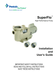
SUPERFLO® VS
VARIABLE SPEED PUMP
INSTALLATION AND
USER’S GUIDE
IMPORTANT SAFETY INSTRUCTIONS
READ AND FOLLOW ALL INSTRUCTIONS
SAVE THESE INSTRUCTIONS
ii
CUSTOMER SERVICE / TECHNICAL SUPPORT
If you have questions about ordering Pentair Aquatic Systems replacement parts, and pool products, please contact:
Customer Service and Technical Support, USA
(8 A.M. to 4:30 P.M. — Eastern/Pacific Times)
Sanford, North Carolina (8 A.M. to 4:30 P.M. ET)
Phone: (800) 831-7133
Fax: (919) 566-8920
Phone: (919) 566-8000
Fax: (800) 284-4151
Moorpark, California (8 A.M. to 4:30 P.M. PT)
Web site
Phone: (805) 553-5000 (Ext. 5591)
Visit www.pentairpool.com or www.staritepool.com
Fax: (805) 553-5515
TABLE OF CONTENTS
Important Pump Warning and
Safety Instructions ................................................ ii
Pump Overview ......................................................
Pump Overview and Features
General Features
Controller Features
Controller Overview
Control Panel LEDs and Functions
1
1
1
1
2
3
Quick Start Guide .................................................. 4
4
Factory Default Schedule
4
User-Defined Schedule
Control Panel Overview ........................................ 5
5
Navigation
Operating the Pump ..............................................
Keypad Overview
Setting a Schedule
Schedule Tables
Pump Operation from Control Panel
Override
Schedule Advance
Key Lockout
Time Out
Temporary Stop with Automation/Serial Input
Reset Factory Defaults
Priming
Care and Maintenance
6
6
6
6
7
8
8
9
9
9
10
10
10
P/N 350880 Rev. A 8/19/13
SUPERFLO® VS Variable Speed Pump Installation and User’s Guide
Wiring Installation .................................................
Wiring Overview
Control with Automation System Inputs
DIP Switches
11
12
14
14
Maintenance ..........................................................
Pump Strainer Basket
Cleaning Pump Strainer Basket
Winterizing
15
15
15
15
Servicing ................................................................
Electric Motor Care
Shaft Seal Replacement
Pump Disassembly
Pump Reassembly
Restart Instructions
16
16
16
16
17
17
Troubleshooting .................................................... 18
20
Fault Status
Replacement Parts ................................................ 21
Pump Performance Curves .................................. 22
22
Pump Specifications
22
Pump Dimensions
iii
IMPORTANT PUMP WARNING AND SAFETY INSTRUCTIONS
IMPORTANT NOTICE
This guide provides installation and operation instructions
for the SuperFlo® VS Variable Speed Pump. Consult Pentair with any
questions regarding this equipment.
Attention Installer: This guide contains important information about the
installation, operation and safe use of this product. This information should
be given to the owner and/or operator of this equipment after installation
or left on or near the pump.
Attention User: This manual contains important information that will help
you in operating and maintaining this product. Please retain it for future
reference. Warnings and safety instructions for Pentair Aquatic Systems
pumps and other related products are available at:
http://www.pentairpool.com/pool-owner/safety-warnings/ or call
(800) 831-7133 for additional free copies of these instructions.
READ AND FOLLOW ALL INSTRUCTIONS
SAVE THESE INSTRUCTIONS
When installing and using this electrical equipment, basic safety
precautions should always be followed, include the following:
Do not permit children to use this product.
RISK OF ELECTRICAL SHOCK. Connect only to
a branch circuit protected by a ground-fault circuitinterrupter (GFCI). Contact a qualified electrician if you cannot verify that
the circuit is protected by a GFCI.
This unit must be connected only to a supply circuit
that is protected by a ground-fault circuit-interrupter
(GFCI). Such a GFCI should be provided by the installer and should be
tested on a routine basis. To test the GFCI, push the test button. The
GFCI should interrupt power. Push the reset button. Power should be
restored. If the GFCI fails to operate in this manner, the GFCI is defective. If the GFCI interrupts power to the pump without the test button
being pushed, a ground current is flowing, indicating the possibility of
an electric shock. Do not use this pump. Disconnect the pump and have
the problem corrected by a qualified service representative before using.
This pump is for use with permanent swimming
pools and may also be used with hot tubs and spas
if so marked. Do not use with storable pools. A permanently-installed
pool is constructed in or on the ground or in a building such that it cannot
be readily disassembled for storage. A storable pool is constructed so
that it is capable of being readily disassembled for storage and
reassembled to its original integrity.
FAILURE TO FOLLOW ALL INSTRUCTIONS AND
WARNINGS CAN RESULT IN SERIOUS BODILY
INJURY OR DEATH. THIS PUMP SHOULD BE INSTALLED AND
SERVICED ONLY BY A QUALIFIED POOL SERVICE PROFESSIONAL.
INSTALLERS, POOL OPERATORS AND OWNERS MUST READ THESE
WARNINGS AND ALL INSTRUCTIONS IN THE OWNER’S MANUAL
BEFORE USING THIS PUMP. THESE WARNINGS AND THE OWNER’S
MANUAL MUST BE LEFT WITH THE POOL OWNER.
SUCTION ENTRAPMENT HAZARD: STAY OFF
THE MAIN DRAIN AND AWAY FROM ALL SUCTION
OUTLETS!
F
This is the safety alert symbol. When you see this
symbol on your system or in this manual, look for
one of the following signal words and be alert to
the potential for personal injury.
Warns about hazards that can cause death,
serious personal injury, or major property damage
if ignored.
Warns about hazards that may cause death,
serious personal injury, or major property damage
if ignored.
Warns about hazards that may or can cause
minor personal injury or property damage
if ignored.
NOTE indicates special instructions not related to hazards.
Carefully read and follow all safety instructions in this manual and on
equipment. Keep safety labels in good condition; replace if missing
or damaged.
General Warnings
• Never open the inside of the drive motor enclosure. There is a
capacitor bank that holds a 230 VAC charge even when there is no
power to the unit.
• The pump is not submersible.
• The pump is capable of high flow rates; use caution when installing
and programming to limit pumps performance potential with old or
questionable equipment.
• Code requirements for the electrical connection differ from state
to state. Install equipment in accordance with the current National
Electrical Code and all applicable local codes and ordinances.
• Before servicing the pump; switch OFF power to the pump by
disconnecting the main circuit to the pump.
• This appliance is not intended for use by persons (including
children) of reduced physical, sensory or mental capabilities, or
lack of experience and knowledge, unless they have been given
supervision or instruction concerning the use of the appliance by a
person responsible for their safety.
THIS PUMP PRODUCES HIGH LEVELS OF SUCTION AND CREATES
A STRONG VACUUM AT THE MAIN DRAIN AT THE BOTTOM OF THE
BODY OF WATER. THIS SUCTION IS SO STRONG THAT IT CAN TRAP
ADULTS OR CHILDREN UNDER WATER IF THEY COME IN CLOSE
PROXIMITY TO A DRAIN OR A LOOSE OR BROKEN DRAIN COVER
OR GRATE.
RISK OF ELECTRICAL SHOCK OR ELECTROCUTION: PUMPS REQUIRE HIGH VOLTAGE
WHICH CAN SHOCK, BURN, OR CAUSE DEATH.
BEFORE WORKING ON PUMP! Always disconnect
power to the pool pump at the circuit breaker from
the pump before servicing the pump. Failure to do
so could result in death or serious injury to service
person, pool users or others due to electric shock.
THE USE OF UNAPPROVED COVERS OR ALLOWING USE OF THE
POOL OR SPA WHEN COVERS ARE MISSING, CRACKED OR BROKEN
CAN RESULT IN BODY OR LIMB ENTRAPMENT, HAIR ENTANGLEMENT, BODY ENTRAPMENT, EVISCERATION AND/OR DEATH. The suction at a drain or outlet can cause:
Limb Entrapment: When a limb is sucked or inserted into an opening
resulting in a mechanical bind or swelling. This hazard is present when
a drain cover is missing, broken, loose, cracked or not properly secured.
Hair Entanglement: When the hair tangles or knots in the drain cover,
trapping the swimmer underwater. This hazard is present when the flow
rating of the cover is too small for the pump or pumps.
SUPERFLO® VS Variable Speed Pump Installation and User’s Guide
iv
Pentair Water Pool and Spa®
IMPORTANT SAFETY INSTRUCTIONS
For Installation of Electrical Controls at Equipment Pad
(ON/OFF Switches, Timers and Automation Load Center)
IMPORTANT PUMP WARNING AND SAFETY INSTRUCTIONS
Install all electrical controls at equipment pad, such as on/off
For
Installation
Electrical
Controls at Equipment Pad (ON/OFF
Body Entrapment: When a portion of the body is held against the drain
switches,
timers, and control of
systems,
etc. to allow the
operation (startup, shut-down, or servicing) of any pump or
Switches,
Timers and Automation Load Center)
cover trapping the swimmer underwater. This hazard is present when the
filter so the user does not place any portion of his/her body
over or near the pump strainer lid, filter lid or valve closures.
drain cover is missing, broken or the cover flow rating is not high enough
Install
allspace
electrical
This installation should allow the user
enough
to stand controls at equipment pad, such as
clear of the filter and pump during system start-up, shut down
for the pump or pumps.
on/off switches, timers, and control systems, etc. to
or servicing of the system filter.
allow the operation (startup, shut-down, or servicing)
Evisceration/Disembowelment: When a person sits on an open pool
Pentair Water Pool and Spa
of any pump or filter so the user does not place any
IMPORTANT
SAFETY
INSTRUCTIONS
(particularly a child wading pool) or spa outlet and suction is applied
directly
For Installation of Electrical Controls at Equipment Pad
(ON/OFF
Switches, Timers and Automation Load Center) portion of his/her body over or near the pump strainer
to the intestines, causing severe intestinal damage. This hazard
is present
lid, filter lid or valve closures. This installation should
when the drain cover is missing, loose, cracked, or not properly secured.
allow the user enough space to stand clear of the
Mechanical Entrapment: When jewelry, swimsuit, hair decorations,
Install all electrical controls at equipment pad, such as on/off
filter and pump during system start-up, shut down or
and control systems, etc. to allow the
finger, toe or knuckle is caught in an opening of an outlet orswitches,
drain timers,
cover.
operation (startup, shut-down, or servicing) of any pump or
servicing of the system filter.
filter so theloose,
user does not place any portion of his/her body
This hazard is present when the drain cover is missing, broken,
over or near the pump strainer lid, filter lid or valve closures.
This installation should allow the user enough space to stand
cracked, or not properly secured.
clear of the filter and pump during system start-up, shut down HAZARDOUS PRESSURE: STAND CLEAR OF
®
NOTE: ALL SUCTION PLUMBING MUST BE INSTALLEDorINservicing of the system filter.
ACCORDANCE WITH THE LATEST NATIONAL AND LOCAL CODES,
STANDARDS AND GUIDELINES.
•
•
•
•
•
•
•
TO MINIMIZE THE RISK OF INJURY DUE TO
SUCTION ENTRAPMENT HAZARD:
A properly installed and secured ANSI/ASME A112.19.8 approved
anti-entrapment suction cover must be used for each drain.
Each suction cover must be installed at least three (3’) feet apart,
as measured from the nearest point to nearest point.
Regularly inspect all covers for cracks, damage and advanced
weathering.
If a cover becomes loose, cracked, damaged, broken or is missing,
replace with an appropriate certified cover.
Replace drain covers as necessary. Drain covers deteriorate over
time due to exposure to sunlight and weather.
Avoid getting hair, limbs or body in close proximity to any suction
cover, pool drain or outlet.
Disable suction outlets or reconfigure into return inlets.
A clearly labeled emergency shut-off switch for the
pump must be in an easily accessible, obvious place.
Make sure users know where it is and how to use it in case of emergency.
The Virginia Graeme Baker (VGB) Pool and Spa Safety Act creates
new requirements for owners and operators of commercial swimming
pools and spas.
Commercial pools or spas constructed on or after December 19, 2008,
shall utilize:
(A) A multiple main drain system without isolation capability with suction
outlet covers that meet ASME/ANSI A112.19.8a Suction Fittings for
Use in Swimming Pools, Wading Pools, Spas, and Hot Tubs and either:
(i) A safety vacuum release system (SVRS) meeting ASME/ANSI
A112.19.17 Manufactured Safety Vacuum Release systems (SVRS)
for Residential and Commercial Swimming Pool, Spa, Hot Tub,
and Wading Pool Suction Systems and/or ASTM F2387 Standard
Specification for Manufactured Safety Vacuum Release Systems
(SVRS) for Swimming pools, Spas and Hot Tubs or
(ii) A properly designed and tested suction-limiting vent system or
(iii) An automatic pump shut-off system.
Commercial pools and spas constructed prior to December 19, 2008,
with a single submerged suction outlet shall use a suction outlet cover
that meets ASME/ANSI A112.19.8a and either:
(A) A SVRS meeting ASME/ANSI A112.19.17 and/or ASTM F2387, or
(B) A properly designed and tested suction-limiting vent system, or
(C) An automatic pump shut-off system, or
(D) Disabled submerged outlets, or
(E) Suction outlets shall be reconfigured into return inlets.
SUPERFLO® VS Variable Speed Pump Installation and User’s Guide
PUMP AND FILTER DURING START UP
Circulation systems operate under high pressure.
When any part of the circulating system (i.e.
locking ring, pump, filter, valves, etc.) is serviced,
air can enter the system and become pressurized.
Pressurized air can cause the pump housing cover,
filter lid, and valves to violently separate which can result in severe
personal injury or death. Filter tank lid and strainer cover must be properly
secured to prevent violent separation. Stand clear of all circulation system
equipment when turning on or starting up pump.
Before servicing equipment, make note of the filter pressure. Be sure
that all controls are set to ensure the system cannot inadvertently start
during service. Turn off all power to the pump. IMPORTANT: Place filter
manual air relief valve in the open position and wait for all pressure
in the system to be relieved.
Before starting the system, fully open the manual air relief valve and place
all system valves in the “open” position to allow water to flow freely from the
tank and back to the tank. Stand clear of all equipment and start the pump.
IMPORTANT: Do not close filter manual air relief valve until all
pressure has been discharged from the valve and a steady stream
of water appears. Observe filter pressure gauge and be sure it is not
higher than the pre-service condition.
General Installation Information
• All work must be performed by a qualified service professional, and
must conform to all national, state, and local codes.
• Install to provide drainage of compartment for electrical components.
• These instructions contain information for a variety of pump models
and therefore some instructions may not apply to a specific model. All
models are intended for use in swimming pool applications. The pump
will function correctly only if it is properly sized to the specific application
and properly installed.
Pumps improperly sized or installed or used in
applications other than for which the pump was
intended can result in severe personal injury or death. These risks may
include but not be limited to electric shock, fire, flooding, suction
entrapment or severe injury or property damage caused by a structural
failure of the pump or other system component.
The pump can produce high levels of suction within
the suction side of the plumbing system. These high
levels of suction can pose a risk if a person comes within the close
proximity of the suction openings. A person can be seriously injured by
this high level of vacuum or may become trapped and drown. It is
absolutely critical that the suction plumbing be installed in accordance
with the latest national and local codes for swimming pools.
SAVE THESE INSTRUCTIONS
1
PUMP OVERVIEW
Pump Overview
Pump Controller Features
The perfect choice for all types of pools, the
SuperFlo ® VS Variable Speed Pump was
specifically designed to be your best choice for
a variety of in-ground pools.
• Simple user interface
Thick walled body parts, a heavy duty TEFC
motor, and highly engineered hydraulics make
this rugged and tested design perfect for any
pool, spa, water feature, or fountain.
• Manual OVERRIDE
• Motor design reduces noise emissions
• UV and rain-proof enclosure
• High efficiency electromechanical motor and control design
All pumps from Pentair Aquatic Systems
incorporate innovative hydraulic engineering
that has been refined for over 40 years.
Compact, rugged, and easy to maintain, the
SuperFlo VS pump will deliver years of reliable
service.
SuperFlo VS Pump
General Features
•
Extremely quiet operation
• Unionized fittings (1.5” and 2”) for simple
replacement
• Cam and Ramp™ Lid for easy cleaning and
maintenance
• Heavy-duty TEFC motor for long life
• Integral volute and pot reduce hydraulic noise
• See-through lid permits easy inspection of
strainer basket
• Self-priming for quick, easy start-up
• UL/CUL/NSF Listed
SUPERFLO® VS Variable Speed Pump Installation and User’s Guide
2
Controller Overview
The SuperFlo® VS Variable Speed Pump
uses a premium efficiency variable speed
motor that provides tremendous program
flexibility in terms of motor speed and duration
settings. The pump is intended to run at
the lowest speeds needed to maintain a
sanitary environment, which in turn minimizes
energy consumption. Pool size, the presence
of additional water features, chemicals
used to maintain sanitary conditions, and
environmental factors will impact optimal
programming necessary to maximize energy
conservation.
Digital Input
Connector
Control Panel
Buttons
DIP Switch
This pump is for use with 208-230 Vrms
nominal, and in pool pump applications ONLY.
Connection to the wrong voltage, or use in other application may
cause damage to equipment or personal injury.
The integrated electronics interface controls
the speed settings as well as the run
durations. The pump can operate at speeds
ranging between 600 and 3450 RPM and is
rated for 208-230 Vrms at an input frequency
of 60 Hz.
Program customization may require some trialand-error to determine the most satisfactory
settings as dictated by the conditions. In most
cases, setting the pump at the lowest speed
for the longest duration is the best strategy
to minimize energy consumption. However,
conditions may require running the pump at a
higher speed for some duration of time each
day to maintain proper filtration to achieve
satisfactory sanitation.
The control panel key pad is located on top of
the pump. To the right of the STEP buttons
is the OVERRIDE button. Use this button to
operate the pump at speeds outside of the
normal operating schedule.
Note: Optimize the pump to suit individual pool
conditions. Specific conditions including pool
size, other devices, features and environmental
factors can all impact the optimal settings.
SUPERFLO® VS Variable Speed Pump Installation and User’s Guide
AC Power
Connection
SuperFlo VS Pump
3
Control Panel LEDs and Function Overview
LED Indication and Functionality Table
X
*
**
#
Power
START
FAULT
STEP1
STEP2
STEP3
OVERRIDE
SETTING
SETTING
BARGRAPH
X
Step1
X
X
Step2
X
X
Step3
X
X
Override
X
X
X
X
X
X
X
*
*
*
X
X
X
X
X
**
**
**
**
**
**
**
**
**
**
**
**
X
X
*
X
X
*
*
X
X
X
X
X
X
X
X
X
X
X
X
*
X
*
X
*
X
*
X
*
X
*
X
*
X
X
X
SUPERFLO® VS Variable Speed Pump Installation and User’s Guide
4
QUICK START GUIDE
Quick Start Instruction
User-defined custom schedule
If power is connected to the SuperFlo® VS Variable
Speed Pump motor, pressing any of the following
buttons referred to in the following section could result in the motor
starting. Failure to recognize this could result in personal injury or
damage to equipment.
Using the factory default schedule
The following table describes the factory default
settings for DURATION and SPEED order:
Button
Duration
(In Hours)
Speed
(In RPM)
STEP 1
4
3100
STEP 2
4
2600
STEP 3
8
1600
OVERRIDE
2
3450
Pressing the START key will start the pump based
on the factory default schedule.
NOTE: If power is cycled to the pump and the
user does not press the STOP key, the pump will
automatically start and run the programmed default
schedule shown in the chart above. This feature
ensures that the pump will re-start in the event of a
power outage. The pump will start on STEP 1.
Figure 1: Duration LED
Figure 2: Speed LED
SUPERFLO® VS Variable Speed Pump Installation and User’s Guide
NOTE: The pump must be Stopped (Press
STOP Key) when programming DURATION and
SPEED of the STEP 1, STEP 2, and STEP 3
keys. OVERRIDE DURATION and SPEED can
be programmed when the pump is either stopped
or running.
To set the DURATION and SPEED for STEP 1,
STEP 2, STEP 3 & OVERRIDE keys:
Press the STEP 1 key. The STEP 1 button and
DURATION setting LEDs will illuminate. The bar
graph will show default DURATION for STEP 1,
see figure 1.
1. Press UP (+) or DOWN (-) arrows to
change the DURATION.
2. Press the STEP 1 key again to change
the SPEED setting. The SPEED setting
LED will illuminate. The bar graph will
show default SPEED for STEP 1, see
figure 2.
3. Press UP (+) or DOWN (-) arrows to
change the SPEED.
4. Press any STEP or OVERRIDE key
to save the DURATION and SPEED
settings for STEP 1. To revert back to
the previously stored setting, press the
STOP key.
5. Press STEP 2, STEP 3, or OVERRIDE
key. Repeat steps 1-4 to program the
corresponding DURATION and SPEED
for each button.
6. Press START to run the pump based on
the programmed 24 hour schedule.
7. To stop the pump, press the STOP
button.
NOTE: The pump can only be set to operate on a
24-hour schedule. If a user attempts to program
a schedule with a combined duration for all three
steps greater than 24 hours, the pump software
will retain the current STEP time duration only,
and will zero out the other two STEP time settings. As an example, if STEP 1 equals eight (8) hours,
STEP 2 equals nine (9) hours, and STEP 3 equals
eight (8) hours – for a combined 25 hours – the
pump will retain the setting for the current Step
being programed and zero out the remaining two.
For details regarding the set-up of the three steps
as part of a 24-hour schedule, see page 6.
NOTE: If using external devices it is the users
responsibility to verify appropriate power and
speed conditions. Refer to proper external device
manual.
5
CONTROL PANEL OVERVIEW
Navigation Overview
•
•
+, - keys Increase/decrease selected value.
Pressing any key following a change accepts the current value displayed inside the setting.
Active Step
LEDs (x4) Programming
Buttons (x4)
Speed LED
Power LED
Duration (Hrs.)LED
Fault LED
Start Button
Stop Button
Bar Graph
+ / - Buttons
Figure 3: Control Panel
If power is connected to the SuperFlo® VS Variable Speed Pump motor, pressing any of the
following buttons referred to in this section could result in the motor starting. Failure to recognize
this could result in personal injury or damage to equipment.
Note: The START button must be pressed for the pump to operate. The START LED will illuminate after the
button has been pressed indicating the pump is capable of operating. Pressing the stop button will turn off
the START LED and stop the motor if running.
SUPERFLO® VS Variable Speed Pump Installation and User’s Guide
6
OPERATING THE PUMP
Keypad Overview
Schedule Tables
If power is connected to the SuperFlo® VS Variable Speed Pump motor, pressing any of
the following buttons referred to in this section could result in the motor starting. Failure
to recognize this could result in personal injury or damage to equipment.
1.
STEP 1 (Set Schedule)
2.
STEP 2 (Set Schedule)
3.
STEP 3 (Set Schedule)
4.
OVERRIDE (Settings)
5.START
6.STOP
è DURATION and SPEED
è DURATION and SPEED
è DURATION and SPEED
è DURATION and SPEED
Set a Schedule
If power is connected to the pump motor, pressing any of the following buttons referred
to in this section could result in the motor starting. Failure to recognize this could result
in personal injury or damage to equipment.
Set the DURATION and SPEED for the pump using the keys on
the User Interface. The schedule is based on a 24-hour schedule
and will repeat each day of the week.
Use the tables below to record a personalized
operating schedule. Recording the planned
schedule in the table below will make the
programming process easier and will help the
user remember the custom settings in case of
inadvertent loss of schedule. The user interface
will not allow the user to program an overlap
between different STEPs of the schedule. The
STEP currently being set will always take priority
over any previous settings. In the event a user
attempts to program with a combined duration
greater than 24 hours, the current STEP setting
will be retained whereas the other two STEP
settings will be cleared to zero hours requiring
the user to reset them. Prior to beginning the
actual programming process, it is advisable
for the user to review the planned schedule as
outlined in chart form to ensure the cumulative
duration is not greater than 24 hours and no
overlaps exist. It is always a good idea to double
check your programmed settings for accuracy
once you have completed the programming
process.
Setup #1
Step 1
Step 2
Step 3
Duration
Speed
Setup #2
Step 1
The highest speed rating for the pump is 3450 RPM
and the lowest is 600 RPM. Unless a new user-defined
schedule is entered, the pump will operate based on the
following factory default schedule:
Button
Duration
(In Hours)
Speed
(In RPM)
STEP 1
4
3100
STEP 2
4
2600
STEP 3
8
1600
OVERRIDE
2
3450
Table 3: Factory default schedule
SUPERFLO® VS Variable Speed Pump Installation and User’s Guide
Duration
Speed
Table 4: Custom Schedule
Step 2
Step 3
7
Operating the SuperFlo® VS Variable Speed
Pump from the Control Panel
If power is connected to the pump motor, pressing any of the following buttons
referred to in this section could result in the motor starting. Failure to recognize this
could result in personal injury or damage to equipment.
NOTE: Pressing a STEP key other than for
the STEP currently running will cause an
immediate transition to the newly selected
STEP. The pump will continue with the
programmed schedule from that point
forward.
1. Press the START key and the pump will run the
programmed 24 hour duration schedule. The
START event will be stored. Should a power
outage occur, the pump will automatically re-start
at STEP 1 when power is restored.
NOTE: If STOP is pressed during normal
schedule operation, the 24 hour schedule
will stop. When START is pressed again,
the 24 hour schedule will start from STEP 1.
2. The pump will always run the PRIMING sequence
when it starts from the OFF state, including
when it automatically restarts following a power
outage. The default Prime setting is defined in the
“Priming” section, see page 10.
NOTE: If power is lost while the pump
is running a 24 hour schedule, upon
restoration of power the pump will start the
24 hour schedule from STEP 1.
3. The pump then starts running in STEP 1 at
the programmed DURATION and SPEED. The
“ACTIVE LED” for STEP 1 will switch ON. The
DURATION and SPEED setting LEDs along with
the respective bar graph LED will blink back and
forth every three (3) seconds.
NOTE: If an automation control system
input (provided from an external source)
is detected, the pump will start running
on the STEP 1, STEP 2, STEP 3, or
OVERRIDE speed corresponding to
that automation input. Upon removing
the automation input (provided from an
external source), the pump will stop and
the user will need to press START to begin
the 24 hour schedule operation. However,
if START was already pressed prior to
receiving an automation input, then the
pump will resume running the 24 hour
schedule once the input is removed.
NOTE: Pressing STOP at any time turns
the pump OFF and clears the start time for
the 24 hour schedule.
4. This sequence will then repeat for STEP 2 and
then STEP 3 without the pump stopping.
5. At the end of STEP 3, the pump will wait if
necessary for the completion of the 24-hour
schedule. During this waiting period (if applicable), all of the “active step LEDs” will
remain OFF. However, the START LED will still
be illuminated. After completion of the 24 hour
schedule, the system restarts at STEP 1 and this
cycle will repeat indefinitely until the user presses
the STOP key.
SUPERFLO® VS Variable Speed Pump Installation and User’s Guide
8
Override
Schedule Advance
The SuperFlo® VS Variable Speed Pump is equipped
with an OVERRIDE feature, which can be engaged
to temporarily run at higher or lower speeds ranging
between 600 to 3450 RPM. Once the OVERRIDE
duration has elapsed, the pump will automatically return
to the programmed schedule.
The Schedule Advance mode allows the user to
press the START button at one time of the day,
with the 24-hour schedule starting at a different
time of day. The pump can run in the Schedule
Advance mode (by using the OVERRIDE button)
and upon completion will begin the programmed 24
hour schedule at STEP 1 DURATION and SPEED.
1. Pressing the OVERRIDE key while the pump is
running will cause the pump to start running in the
OVERRIDE mode at the programmed DURATION
and SPEED. The “active LED” for OVERRIDE will
illuminate. The DURATION and SPEED setting
LEDs along with its respective bar graph LED will
blink back and forth at three (3) second intervals.
2. The UP (+) / DOWN (-) arrows allow the user to
configure OVER RIDE DURATION and SPEED.
These settings can be changed while the pump is
running. These settings are stored each time the
UP (+) / DOWN (-) arrows are pressed.
The following steps should be followed to set
Schedule Advance mode:
Do not perform any maintenance on the motor while the motor is in Schedule
Advance Mode. The motor may start without warning. This event could cause
death or serious personal injury.
1. With the pump stopped, press and hold
the START key for more than three (3)
seconds. The START LED will blink at a rate
of one second per pulse. The DURATION
setting LED and respective bar graph LED
will remain turned ON until the Schedule
Advance mode is complete.
2. Press the UP (+) or DOWN (-) arrows to set
the desired delay time after which the 24hour schedule should start. The Schedule Advance mode will automatically start after
the desired delay time is selected. The
Schedule Advance mode can be cancelled
by pressing the STOP key.
NOTE: When the OVERRIDE duration ends, the
pump resumes the 24 hour schedule at the point
in the currently programmed 24 hour schedule
where it normally would be running at that time.
The OVERRIDE duration will not affect the start or
stop times of the 24 hour schedule. For example, if
OVERRIDE runs during a period overlapping with a
later part of STEP 1 and an early part of STEP 2, the
start time of STEP 3 is not affected.
NOTE: Pressing/Holding OVERRIDE key for more than
three (3) seconds will cancel OVERRIDE mode.
NOTE: During the OVERRIDE mode, the pump will not
start with the priming sequence.
NOTE: It is recommended that you do not set the
OVERRIDE duration to 0 HRS. Setting the OVERRIDE
duration to 0 HRS will not allow you to change the
duration setting while the motor is running. The
motor will have to be stopped in order to change the
OVERRIDE settings if the duration is set to 0 HRS.
SUPERFLO® VS Variable Speed Pump Installation and User’s Guide
NOTE: The OVERRIDE
button will still function when
the Schedule Advance mode
is active. This will allow the
user to run the pump during
the period of the Schedule
Advance mode.
NOTE: While the pump is
in the Schedule Advance
mode, if a user presses
STEP 1, STEP 2, STEP 3 or
the START key, the system
will start the normal schedule and the Schedule Advance
mode will be canceled.
NOTE: While the pump is in the Schedule Advance
mode, if a user presses the STOP key, then the Schedule
Advance mode is canceled.
NOTE: If power is lost while the pump is in the Schedule
Advance mode, then the 24-hour schedule will
automatically start when power is restored.
9
Time Out
Key Lockout
Key lockout will not prevent the motor from being stopped by pressing the
STOP button. If the motor is operating in “key lockout” mode, and being
controlled through an automation input, the motor will only temporarily stop
(4 min.) it will then restart.
The SuperFlo® VS Variable Speed Pump user interface has
a “key lockout” feature to prevent unwanted changes to the
settings.
To lock the keys, hold down the ”STEP 1, STEP 2, and STEP
3” buttons all at the same time for at least three seconds. The “active LEDs” for STEP 1, STEP 2, and STEP 3 will
blink for 30 seconds indicating that the keypad is locked.
The user can unlock the keys by holding down the same
three STEP buttons for at least three seconds. The “active
LEDs” for STEP 1, STEP 2, and STEP 3 will illuminate
temporarily indicating the keypad is unlocked.
NOTE: While operating in “key lockout” mode the motor
can still be stopped by pressing the stop key. If no input is
present the motor will remain stopped. If the motor is being
controlled by an automation control system input the motor
will only temporarily stop for 4 minutes.
The “time out” feature that will allow the user to
temporarily stop the pump for maintenance work
without disrupting the 24 hour schedule (i.e., for
backwashing the filter). If the pump is currently
running, the user can press and hold the START
button for more than three (3) seconds and the
pump will stop and remain off until the user presses
and holds the START button again for more than
three (3) seconds. The START and OVERRIDE
buttons will blink once every second indicating that
the “time out” feature is enabled. These LEDs will
stop blinking once this feature is cancelled.
Temporary Stop with Automation
Control System Input
Temporary stop functionality only works while the pump is being controlled
by an automation input. If the motor is being controlled by the integrated
key pad and STOP is pressed, the motor will stop and remain stopped.
The pump has a “temporary stop” feature that will
immediately stop the pump when being controlled by an
automation input. The user can press the STOP button
while the pump is running and the pump will stop and stay
off for four (4) minutes. Once this time has elapsed, the
pump will return to normal operation and accept an input
from an automation input source.
NOTE: If the pump is operating from automation input, the
‘0 RPM’ LED of the bar graph will blink once every second
indicating the “temporary stop” feature has been activated.
After the specified time period, the pump will return to
normal operation and accept an input from any automation
input source. Refer to page 14 for additional details on
automation control system inputs.
SUPERFLO® VS Variable Speed Pump Installation and User’s Guide
10
Reset Factory Defaults
The SuperFlo® VS Variable Speed Pump user interface has a “Reset to Factory Defaults” feature to restore the
schedule settings back to the original values programmed at the factory. The user must press and hold the STOP
and OVERRIDE buttons for three (3) seconds to reset the settings back to factory defaults. All of the UI bar graph
LED’s will flash three (3) times to confirm the settings were restored to factory defaults.
Priming
The pump will always run the PRIMING sequence when starting from the OFF state, except when starting in
OVERRIDE. The factory Prime settings are 3450 RPM for three (3) minutes.
Care and Maintenance
The pump is both reliable and robust in harsh environments. However, this product does contain electronics
that are cooled by a fan mounted to the pump. In order to ensure optimum reliability of this product, it is
recommended to clean the fan inlet on the back of the pump once a month. It is also important to keep this area
free of large debris such as leaves, branches, mulch, plastic bags, etc.
SUPERFLO® VS Variable Speed Pump Installation and User’s Guide
11
ELECTRICAL WIRING INSTALLATION
RISK OF ELECTRICAL SHOCK OR ELECTROCUTION. The SuperFlo® VS Variable Speed Pump must be installed by a
licensed or certified electrician or a qualified service professional in accordance with the National Electrical Code and all applicable local codes and ordinances. Improper installation will create an electrical hazard which could result in death or serious injury
to users, installers, or others due to electrical shock, and may also cause damage to property.
Always disconnect power to the pump at the circuit breaker before servicing the pump. Failure to do so could result in
death or serious injury to service people, pool users or others due to electric shock and/or property damage.
Read all servicing instructions before working on the pump.
Wiring
1. Be sure all electrical breakers and switches are turned
off before wiring motor.
8. Connect the wire from the accessible wire
connector on the motor to all metal parts of the
swimming pool, spa, or hot tub structure and
to all electrical equipment, metal conduit, and
metal piping within 5 feet (1.5 M) of the inside
walls of the swimming pool, spa, or hot tub. For
Canada, a 6 AWG or larger solid copper bonding
conductor is required.
2. Be sure that the wiring voltage matches the motor
voltage (230 VAC). If they do not match, the motor
can overheat.
3. Choose a wire size for the pump in accordance with
the current National Electrical Code and all applicable
local codes and ordinances. When in doubt use a
heavier gauge (larger diameter) wire. Heavier gauge
will allow the motor to run cooler and more efficient.
9. The pump should be permanently connected to
either a circuit breaker, 2-pole timer or 2-pole
relay. If AC power is supplied by a GFCI circuit
breaker, use a dedicated circuit breaker that has
no other electrical loads.
4. Be sure all electrical connections are clean and tight.
5. Cut wires to the appropriate length so they do not
overlap or touch when connected to the terminal
board.
10. Connect the pump permanently to a circuit.
Make sure no other lights or appliances are on
the same circuit.
6. Permanently ground the motor using the ground
screw located on the inside rear of the controller
interface, see figure 4. Use the correct wire size
and type specified by the current National Electrical
Code. Be sure the ground wire is connected to an
electrical service ground.
Note: When the pump is started and stopped by
removing power with a relay or timer, a two-pole
device should be used to apply and remove power
to both POWER LINE TERMINALS.
7. Bond the motor to the pool structure in accordance
with the current National Electrical Code. UL requires
use of a solid copper bonding conductor not smaller
than 8 AWG.
Note: When pump is mounted permanently within 5 ft. (1.5 M) of the inside walls of a swimming pool, you
must use a No. 8 AWG or larger conductor to connect to
bonding conductor lug.
Grounding Screw
Figure 4.
SUPERFLO® VS Variable Speed Pump Installation and User’s Guide
12
Wiring
The SuperFlo® VS Variable Speed Pump controller must be wired according to the locally adopted version of the
National Electrical Code. A licensed, qualified electrician should complete the wiring for this product.
The controller is designed to operate with 208-230 Vrms, single phase power.
The pump is designed to handle either a bare wire connection or a quick disconnect connection. The quick
disconnect tab is 0.250” and will handle any commonly available mating connectors. For a direct wire connection,
the wire insulation should be stripped to a length of approximately 0.33.” The terminal block is capable of handling
solid or stranded wire up to 12 AWG in size. The screw for the mains connections should be properly tightened to
a torque value of 10 in-lb.
Pin #
Wire Color
Description
L1
Black
Hot 1
L2
Red or White
Hot 2
Ground screw
Green
Earth
Pin #
Wire Color
Description
J201 - 1
Red
+12V
J201 - 2
Black
A
J201 - 3
Yellow
B
J201 - 4
Green
COM
Table 2: Communication Connections
Table 1: Main Connections
Power should be turned off when installing, servicing, or repairing electrical components.
Observe all warning notices posted on the existing equipment, pump, and in these
installation instructions.
L2
(RED OR WHITE)
L1
(BLACK)
208-230V POWER
SOURCE
EARTH
EARTH
Figure 5: Main Connection Diagram
SUPERFLO® VS Variable Speed Pump Installation and User’s Guide
13
Pump Controller
Automation System or
Solar System Controller
UI DIGITAL
INPUT CONNECTOR
J202
STEP 1
(pin 1)
STEP 2
(pin 2)
STEP 3
(pin 3)
EXTERNAL SUPPLY
Vac or
VDC
GND
OVER RIDE
(pin 4)
COMMON
(pin 5)
External Supply Range:
18-30V AC (24V AC+/- 20%)
9-30V DC (12/24V DC +/- 20%)
Figure 6: Wiring Diagram for Automation Control System Inputs
Access to these terminals is in close proximity to the mains connectors which carry line voltage capable of
causing personal injury or damaging the equipment if contact is made. Power should be turned off when
accessing this area.
Figure 7: Automation Control System Input Connector
SUPERFLO® VS Variable Speed Pump Installation and User’s Guide
14
Control with Automation Control System Inputs
The user can run the SuperFlo® VS Variable Speed Pump at the programmed STEP 1, STEP 2, STEP 3,
or OVERRIDE speeds by utilizing the four automation control system inputs. STEP 1, STEP 2, STEP 3, or
OVERRIDE are equivalent to input 1, 2, 3 or OVRD respectively. NOTE: The controller is rated to accept inputs of 18V-30V AC (24V AC+/- 20%) and 9-30V DC (12/24V DC +/20%).
NOTE: The pump will detect either a 50/60Hz for AC input or an active high signal for DC inputs.
The items below describe the functionality of the inputs:
1. If the user provides any one of the four (4) inputs, then the corresponding ACTIVE STEP LED will blink every one (1) second. The SPEED LED and corresponding bar graph LED will be illuminated to indicate the input is functioning properly.
2. The START LED will be OFF when an input is present.
Access to these terminals is in close proximity to the mains connectors which carry line voltage
capable of causing personal injury or damaging the equipment if contact is made. Power should
be turned off when accessing this area.
NOTE: A generic wiring diagram is provided in figure 6 (on page 13) for connecting the pump to an “Automation
System Controller”. This concept can be applied to a solar system or any other type of control system.
NOTE: There is no schedule for automation system inputs. The timing for each speed is controlled directly by
the inputs.
NOTE: The digital inputs have the highest priority amongst all inputs (i.e., keypad or digital). Therefore the User
Interface inputs will be ignored when a digital input is present.
NOTE: If more than one input (switch) is present, then the pump will give priority to the highest number input. Therefore OVERRIDE has highest priority followed by STEP 3, then STEP 2, then STEP 1.
NOTE: If no automation input is detected, the pump will automatically start the 24 hour schedule if the START
key was pressed prior to the application of an input.
NOTE: If using external devices it is the users responsibility to verify appropriate power and speed conditions. Refer to proper external device manual.
DIP Switches
The DIP switches are used for factory programming.
Figure 8: DIP Switches
SUPERFLO® VS Variable Speed Pump Installation and User’s Guide
15
MAINTENANCE
DO NOT open the strainer pot if SuperFlo® VS Variable Speed Pump fails to prime or if pump has been operating without water in
the strainer pot. Pumps operated in these circumstances may experience a build up of vapor pressure and may contain scalding
hot water. Opening the pump may cause serious personal injury. In order to avoid the possibility of personal injury, make sure the
suction and discharge valves are open and strainer pot temperature is cool to touch, then open with extreme caution.
To prevent damage to the pump and for proper operation of the system, clean pump strainer and skimmer baskets regularly.
Pump Strainer Basket
Winterizing
The pump strainer basket (or ‘strainer pot’, ‘hair and lint
pot’), is located in front of the volute. Inside the chamber
is the basket which must be kept clean of leaves and
debris at all times. View basket through the ‘See Through
Lid’ to inspect for leaves and debris.
Regardless of the length of time between filter cleaning,
it is most important to visually inspect the basket at least
once a week. A dirty basket will reduce the efficiency of
the filter and heater and also put an abnormal stress on
the pump motor which would result in a costly repair bill.
You are responsible for determining when freezing
conditions may occur. If freezing conditions are
expected, take the following steps to reduce the risk of
freeze damage. Freeze damage is not covered under
warranty.
To prevent freeze damage, follow the procedures below:
Cleaning the Pump Strainer Basket
1. Turn off the pump at the circuit breaker.
2. Relieve pressure in the system by allowing the water
to cool.
3. Gently tap the clamp in a counter-clockwise direction
to remove the clamp and lid.
4. Remove debris and rinse out the basket. Replace
the basket if it is cracked.
5. Put the basket back into the housing. Be sure to align
the notch in the bottom of the basket with the rib in
the bottom of the volute.
6. Fill the pump pot and volute up to the inlet port with
water.
7. Clean the cover, O-ring, and sealing surface of the
pump pot. Note: It is important to keep the lid O-ring
clean and well lubricated.
8. Reinstall the lid by placing the lid on the pot. Be sure
the lid O-ring is properly placed. Seat the clamp and
lid on the pump then turn clockwise until the handles
are horizontal.
9. Turn the power “ON” at the house circuit breaker. Reset
the pool time clock to the correct time, if applicable.
10. Open the High Flow™ manual air relief valve on top
of the filter.
11. Stand clear of the filter. Start the pump.
12. Bleed air from the filter until a steady stream of water
comes out. Close the High Flow™ Manual Air Relief
Valve.
This SYSTEM operates under high
pressure. When any part of the circulating
system (e.g., Lock Ring, Pump, Filter, Valves, etc.)
is serviced, air can enter the system and become
pressurized. Pressurized air can cause the lid to
separate which can result in serious injury, death,
or property damage. To avoid this potential hazard,
follow above instructions.
1. Shut off electrical power for the pump at the circuit
breaker.
2. Drain the water out of the pump housing by
removing the two thumb-twist drain plugs from the
housing. Store the plugs in the pump basket.
3. Cover the motor to protect it from severe rain, snow
and ice.
Note: Do not wrap motor with plastic or other air tight
materials during winter storage. The motor may be
covered during a storm, winter storage, etc., but never
when operating or expecting operation.
Note: In mild climate areas, when temporary freezing
conditions may occur, run your filtering equipment all
night to prevent freezing.
CLAMP
LID
O-RING
BASKET
VOLUTE
Strainer Pot Assembly
SUPERFLO® VS Variable Speed Pump Installation and User’s Guide
16
SERVICING
Always disconnect power to the SuperFlo® VS Variable Speed Pump at the circuit breaker and disconnect the communication cable
before servicing the pump. Failure to do so could result in death or serious injury to service people, users or others due to electric
shock. Read all servicing instructions before working on the pump.
DO NOT open the strainer pot if pump fails to prime or if pump has been operating without water in the strainer pot. Pumps operated
in these circumstances may experience a build up of vapor pressure and may contain scalding hot water. Opening the pump may
cause serious personal injury. In order to avoid the possibility of personal injury, make sure the suction and discharge valves are
open and strainer pot temperature is cool to touch, then open with extreme caution.
Be sure not to scratch or mar the polished shaft seal faces; seal will leak if faces are damaged. The polished and lapped faces of
the seal could be damaged if not handled with care.
Care of Electric Motor
Pump Disassembly
Protect from heat
All moving parts are located in the rear sub-assembly
of this pump.
Tools required:
1. Shade the motor from the sun.
2. Any enclosure must be well ventilated to prevent
overheating.
3. Provide ample cross ventilation.
Protect against dirt
1. Protect from any foreign matter.
2. Do not store (or spill) chemicals on or near the motor.
3. Avoid sweeping or stirring up dust near the motor
while it is operating.
4. If a motor has been damaged by dirt it may void the
motor warranty.
5. Clean the lid and clamp, O-ring, and sealing surface
of the pump pot.
Protect against moisture
•
•
•
•
•
1/4 inch socket or open end wrench.
3/8 inch socket or open end wrench.
9/16 inch open end wrench.
5/16 Allen Key
Flat blade screwdriver.
To remove and repair the motor subassembly, follow the
steps below:
1. Turn off the pump circuit breaker at the main panel.
2. Drain the pump by removing the drain plugs.
3. Remove the 4 bolts that hold the main pump body
(strainer pot/volute) to the rear sub-assembly.
4. GENTLY pull the two pump halves apart, removing
the rear sub-assembly.
1. Protect from splashing or sprayed water.
2. Protect from extreme weather such as flooding.
3. If motor internals have become wet - let them dry
before operating. Do not allow the pump to operate if
it has been flooded.
4. If a motor has been damaged by water it may void
the motor warranty.
6. Hold the impeller securely in place and remove the
impeller lock screw by using a flat blade screwdriver
or wrench. The screw is a left-handed thread and
loosens in a clockwise direction.
Note: When replacing the motor, be certain that the
motor support is correctly positioned to support the
size of motor being installed.
7. To unscrew the impeller from the shaft, insert a
5/16 Allen key into the center of the motor fan cover
and twist the impeller counter-clockwise.
Shaft Seal Replacement
8. Remove the four bolts from the seal plate to the
motor using a 3/8 inch wrench.
The Shaft Seal consists primarily of two parts, a
rotating member and a ceramic seal.
The pump requires little or no service other than
reasonable care, however, a Shaft Seal may
occasionally become damaged and must be replaced.
5. Remove the three hex head screws holding the
diffuser in position.
9. Place the seal plate face down on a flat surface
and tap out the ceramic seal.
10. Clean the seal plate, seal housing, and the motor
shaft.
Note: The polished and lapped faces of the seal could
be damaged if not handled with care.
SUPERFLO® VS Variable Speed Pump Installation and User’s Guide
17
DO NOT run the pump dry. If the pump is run dry, the mechanical seal will be damaged and the pump will start leaking. If this occurs,
the damaged seal must be replaced. ALWAYS maintain proper water level. If the water level falls below the suction port, the pump will
draw air through the suction port, losing the prime and causing the pump to run dry, resulting in a damaged seal. Continued operation in this manner could
cause a loss of pressure, resulting in damage to the pump case, impeller and seal and may cause property damage and personal injury.
Pump Reassembly
Restart Instructions
1. When installing the replacement seal into the seal
plate, use soapy water to wet the rubber boot before
pressing it into the seal plate.
2. Remount the seal plate to the motor.
3. Before installing the rotating portion of the seal on
the motor shaft, wet the motor shaft with soapy water
and slide the seal onto the motor shaft. Ensure that
the carbon face contacts the ceramic face of the
stationary seat. Press the seal into the seal plate
with your thumbs and wipe off the ceramic with a
clean cloth.
4. Grease the motor shaft thread and screw impeller
onto the motor shaft.
5. Screw in the impeller lock screw (counter-clockwise
to tighten).
6. Remount the diffuser onto the seal plate. Make
sure the plastic pins and holding screw inserts are
aligned.
7. Grease the diffuser quad ring and seal plate O-ring
prior to reassembly.
8. Grease the bolt threads, assemble the motor subassembly to the strainer pot-pump body by using
the two through bolts for proper alignment. Do not
tighten the through bolts until all 4 bolts are in place
and finger tightened.
9. Fill the pump with water.
10. Reinstall the pump lid and plastic clamp; see the
next section, ‘Restart Instructions’.
11. Re-prime the system.
If SuperFlo® VS Variable Speed Pump is installed
below the water level of the pool, close return and
suction lines prior to opening hair and lint pot on pump.
Make sure to re-open valves prior to operating.
Priming the Pump
The pump strainer pot must be filled with water before
the pump is initially started.
Follow these steps to prime the pump:
1. Remove the pump lid plastic clamp. Remove the
pump lid.
2. Fill the pump strainer pot with water.
3. Reassemble the pump cover and plastic clamp onto
the strainer pot. The pump is now ready to prime.
4. Open the air release valve on the filter, and stand
clear of the filter.
5. Turn on the switch or time clock.
6. When water comes out of the air release valve,
close the valve. The system should now be free of
air and recirculating water to and from the pool.
MOTOR
BOLT
MOTOR SLINGER
MOTOR SHAFT
SHAFT SEAL
IMPELLER SCREW
IMPELLER
SEAL PLATE O-RING
SEAL PLATE
DIFFUSER
DIFFUSER SCREW
QUAD RING
Motor Assembly
SUPERFLO® VS Variable Speed Pump Installation and User’s Guide
18
TROUBLESHOOTING
Diagnosing certain symptoms may require close interaction with, or in close proximity to,
components that are energized with electricity. Contact with electricity can cause death, personal
injury, or property damage. When trouble shooting the pump, diagnostics involving electricity
should be cared for by a licensed professional.
Problem
Possible Cause
Corrective Action
Pump failure.
Pump will not prime - Air leak, too much air.
Check suction piping and valve glands on any suction
gate valves. Secure lid on pump strainer pot and be
sure lid gasket is in place. Check water level to be
sure skimmer is not drawing air.
Pump will not prime - Not enough water.
Be sure the suction lines, pump, strainer, and pump
volute are full of water. Be sure valve on suction line
is working and open (some systems do not have
valves). Check water level to make sure water is
available through skimmer.
Pump stainer gasket is clogged.
Clean pump strainer pot.
Pump strainer gasket is defective.
Replace gasket.
Air pockets or leaks in suction line.
Check suction piping and valve glands on any suction
gate valves. Secure lid on pump strainer pot and be
sure lid gasket is in place. Check water level to be
sure skimmer is not drawing air.
Clogged impeller.
Turn off electrical power to the pump.
Disassemble (see page 16, ‘Pump Disassembly’)
Reduced capacity and/or
head.
Clean debris from impeller. If debris cannot be
removed, complete the following steps:
1. Remove left hand thread anti-spin bolt and o-ring.
2. Remove, clean, and reinstall impeller.
Reassemble (see page 17, ‘Pump Reassembly’)
Pump fails to start.
Pump runs then stops.
Pump is noisy.
Pump strainer clogged.
Clean suction trap.
Mains Voltage is not present
1. Replace fuse, reset breaker/GFCI.
2. Tighten mains wire connections.
Pump shaft is locked
Check if the pump can be rotated by hand and
remove any blockage.
Pump shaft is damaged
Replace pump.
Over temperature FAULT
Check that back of pump is free from dirt and debris.
Use compressed air to clean.
Over current FAULT
Pump will automatically restart after one (1) minute.
Debris in contact with fan
Check that back of pump is free from dirt and debris.
Use compressed air to clean.
Debris in strainer basket
Clean strainer basket.
Loose mounting
Check that mounting bolts of pump and pump are
tight.
SUPERFLO® VS Variable Speed Pump Installation and User’s Guide
19
Troubleshooting (Cont.)
Problem
Possible Cause
Corrective Action
Pump runs without flow.
Impeller is loose
Check that pump is spinning by looking at fan on back
of SuperFlo VS Variable Speed Pump. If so, check
that pump impeller is correctly installed.
Air leak
Check plumbing connections and verify they are tight.
Clogged or restricted plumbing
Check for blockage in strainer or suction side piping.
Checked for blockage in discharge piping including
partially closed valve or dirty pool filter.
SUPERFLO® VS Variable Speed Pump Installation and User’s Guide
20
FAULT Status
While the FAULT LED is illuminated the motor will not run, upon clearing the fault, the motor may
automatically resume running depending on where in the schedule the FAULT occurred. This may cause
personal injury or damage to the equipment.
The paragraphs below illustrate the possible faults that can occur with the SuperFlo® VS Variable Speed
Pump. If the pump does not restart automatically following the FAULT, cycle AC power to the pump and wait
five (5) minutes. If this does not correct the situation, please contact Customer Service at 1-800-831-7133.
The pump reads the FAULT status and provides feedback to the user via the FAULT LED. The pump will
illuminate the FAULT LED when a FAULT is present. The pump will stop and remain OFF when the FAULT
is present. Once the FAULT is cleared, if the pump was previously running, it will automatically resume
running the normal schedule.
Below is the behavior of the FAULT LED when a FAULT is detected:
1. When a FAULT is present, and the motor is not running, only the FAULT LED and power LED will illuminate.
2. When a FAULT is present, and the motor is running, then the FAULT LED will illuminate. During the FAULT condition, the bar graph LEDs on the interface will turn OFF. However, the power LED, start LED
& active STEP LED will remain illuminated.
3. When a FAULT is present and the FAULT LED is illuminated, only the STOP key will function. The remaining buttons become disabled.
4. When the FAULT LED is continuously ON (i.e. not blinking), a FAULT is present in the controller. When the FAULT LED is blinking every one (1) second, a FAULT is present in the user interface.
5. When the FAULT has cleared, the FAULT LED will turn OFF.
6. Once the FAULT is cleared, if the pump was previously running, it will automatically resume running the normal schedule.
Please see Troubleshooting (page 19) issues and their resolutions.
SUPERFLO® VS Variable Speed Pump Installation and User’s Guide
21
REPLACEMENT PARTS
SuperFlo® VS Variable Speed Pump Replacement Parts List
4
1
5
2
14
6
23
20
22
18
21
25
17
12
13
19
24
16
15
3
7
11
Item
No.
Part
No.
8
9
10
Description
1 358020Z Motor / Drive
2 355612 SEAL PLATE
3 351094 BASE
4 351090 CLAMP, RAMP & CAM
5 350091 LID
6 357255 O-RING, LID #2-357
7 351089 VOLUTE
8 350093 ADAPTER, 2 req.
9 270141 NUT, 2 req.
10 192115 O-RING DRAIN PLUG, 2 req.
11 357161 DRAIN PLUG, 2 req.
12 072184 WASHER 3/8 in. S/S, 4 req.
13 355621 SCREW ¾-16 X 2¼ HEX HD, 4 req.
14 355619 O-RING SEAL BRACKET
15 350099 O-RING ADAPTER #2-226, 2 req.
16 355030 SEAL DIFFUSER
17 355334 SCREW #8-32 HEX WASHER HD, 3 req.
18 355618 DIFFUSER
19 354290 HEX HEAD SCREW 3/8 - 16, 4 req.
20 355074 IMPELLER
21 355389 SCREW, IMPELLER LOCKING
22 354545 SEAL SET
23 355667 BASKET, LARGE
24 355385 MOTOR SUPPORT
25 350157 SUPERFLO UNION KIT(2 UNIONS, 2 ADAPTERS, 2 O-RINGS PER KIT) SUPERFLO® VS Variable Speed Pump Installation and User’s Guide
22
Pump Performance Curves
SuperFlo® VS Variable Speed Pump
80
OVERRIDE/MAX SPEED 3450 RPM
@ OVERRIDE/MAX SPEED 3450 RPM
STEP/SPEED 1 3100 RPM
STEP/SPEED 2 2600 RPM
70
STEP/SPEED 3 1600 RPM
LOWEST SPEED 600 RPM
TOTAL DYNAMIC FEET OF HEAD
60
@ STEP/SPEED 1 3100 RPM
50
@ STEP/SPEED 2 2600 RPM
40
30
20
@ STEP/SPEED 3 1600 RPM
10
@ LOWEST SPEED 600 RPM
0
0
20
40
60
FLOW (GPM)
80
100
120
Pump Dimensions
Specifications
Overall Ratings
Input Voltage
Input Current
Input Frequency
Control Terminals
9-30V DC (12/24V DC +/- 20%)
Auxiliary Load Terminals
Maximum Continuous Load
208 - 230 Vrms nominal
10.5 - 10.0 Arms
Single phase, 60 Hz
18-30V AC (24V AC+/- 20%) or Speed Range
Environmental Rating
Agency Approval
600 - 3450 RPM
NEMA Type 3R
R/C XDNW2.E302804
R/C XDNW8.E302804
Ambient Conditions
-40ºC to +85ºC (-40ºF to +185°)
0ºC to +50ºC (+32°F to +122°F)
Relative 0 to 95 % non-condensing
Storage
Operating
Humidity
N/A
1.65 THP (Total Horse Power)
9.33 REF
24.03 REF
8.36 REF
10.60REF
10.77 REF
7.70 REF
SUPERFLO® VS Variable Speed Pump Installation and User’s Guide
11.12 REF
NOTES
23
1620 HAWKINS AVE., SANFORD, NC 27330 • (919) 566-8000
10951 WEST LOS ANGELES AVE., MOORPARK, CA 93021 • (805) 553-5000
WWW.PENTAIRPOOL.COM
All Pentair trademarks and logos are owned by Pentair Inc. Pentair Aquatic Systems™, SuperFlo®, Eco-Select® and Cam and Ramp™ are trademarks
and/or registered trademarks of Pentair Water Pool and Spa, Inc. and/or its affiliated companies in the United States and/ or other countries. Unless
expressly noted, names and brands of third parties that may be used in this document are not used to indicate an affiliation or endorsement between
the owners of these names and brands and Pentair Water Pool and Spa, Inc. Those names and brands may be the trademarks or registered trademarks
of those third parties. Because we are continuously improving our products and services, Pentair reserves the right to change specifications without
prior notice. Pentair is an equal opportunity employer.
© 2013 Pentair Water Pool and Spa, Inc. All rights reserved. This document is subject to change without notice.
*350880*
P/N 350880 REV. A 9/5/13
SUPERFLO® VS Variable Speed Pump Installation and User’s Guide