1
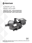
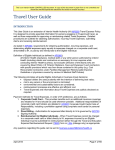
™
SuperFlo
High Performance Pump
Installation
and
User's Guide
IMPORTANT SAFETY INSTRUCTIONS
READ AND FOLLOW ALL INSTRUCTIONS
SAVE THESE INSTRUCTIONS
Customer Service
SOURCE ONE OUTLET, INC.
6315 B Transit Road
Depew, NY 14043
866-262-6845
www.source1outlet.com
Patent D517,570
© 2005 Pentair Water Pool and Spa, Inc. All rights reserved.
This document is subject to change without notice.
1620 Hawkins Ave., Sanford, NC 27330 • (919) 566-8000
10951 West Los Angeles Ave., Moorpark, CA 93021 • (805) 553-5000
Trademarks and Disclaimers: SuperFlo is a trademark of Pentair Water Pool and Spa, Inc. The Pentair Pool Products logo is a registered trademark
of Pentair Water Pool and Spa, Inc. Other trademarks and trade names may be used in this document to refer to either the entities claiming the marks
and names or their products. Pentair Water Pool and Spa, Inc. disclaims any proprietary interest in trademarks and trade names other than its own.
P/N 350096 Rev. B 4/28/06
i
Table of Contents
Important Safety Precautions .............................................................................................. ii
Section 1: Introduction ..................................................................................................... 1
SuperFlo Pump Overview ....................................................................................... 1
General Features ..................................................................................................... 2
Section 2: Electrical Requirements ................................................................................. 3
Wiring Installation ..................................................................................................... 3
Pump Strainer Basket ............................................................................................. 4
Section 3: Maintenance ..................................................................................................... 5
Cleaning the Pump Strainer Basket ........................................................................ 5
Winterizing ............................................................................................................... 6
Electric Motor Care .................................................................................................. 6
Section 4: Servicing .......................................................................................................... 7
Pump Disassembly ................................................................................................. 7
Pump Reassembly/Seal Replacement .................................................................... 8
Shaft Seal ................................................................................................................ 8
Section 5: Restart Instructions ........................................................................................ 9
Priming the Pump .................................................................................................... 9
Section 6: Troubleshooting .............................................................................................. 10
Section 7: Technical Data .................................................................................................. 11
Replacement Parts .................................................................................................. 11
Pump Curve ............................................................................................................ 12
SuperFlo Pump Installation and User’s Guide
ii
IMPORTANT SAFETY PRECAUTIONS
Important Notice:
This guide provides installation and operation instructions for the SuperFlo Pump.
Consult Pentair Water with any questions regarding this equipment.
Attention Installer: This guide contains important information about the installation, operation and safe use of
this product. This information should be given to the owner and/or operator of this equipment after installation or left on
or near the pump.
Attention User: This manual contains important information that will help you in operating and maintaining this
pump. Please retain it for future reference.
WARNING — Before installing this product, read and follow all warning notices and instructions which are
included. Failure to follow safety warnings and instructions can result in severe injury, death,
or property damage. Call (800) 831-7133 for additional free copies of these instructions.
Consumer Information and Safety
The SuperFlo pumps are designed and manufactured to provide many years of safe and reliable service when installed,
operated and maintained according to the information in this manual and the installation codes referred to in later
sections. Throughout the manual, safety warnings and cautions are identified by the “ “ symbol. Be sure to read and
comply with all of the warnings and cautions.
DANGER — Risk of electrical shock or electrocution.
This pool pump must be installed by a licensed or certified electrician or a qualified pool
serviceman in accordance with the National Electrical Code and all applicable local codes
and ordinances. Improper installation will create an electrical hazard which could result in
death or serious injury to pool users, installers, or others due to electrical shock, and may
also cause damage to property.
Always disconnect power to the pool pump at the circuit breaker before servicing the pump.
Ensure that the disconnected circuit is locked out or properly tagged so that it cannot be
switched on while you are working on the pump. Failure to do so could result in serious injury
or death to serviceman, pool users or others due to electric shock.
WARNING — Hazardous Pressure!
This pump produces high pressure. Air can enter the circulation system and become
pressurized. Pressurized air can cause equipment lids (pump, filter, valves, etc.) to blow off.
Always turn off the pump and relieve pressure before opening lids. Failure to do so could
result in serious injury or death to installers, pool users or others and may also cause
damage to property.
SuperFlo Pump Installation and User’s Guide
iii
IMPORTANT SAFETY PRECAUTIONS (continued)
WARNING — Do not operate the pump until you have read and understand clearly all the operating instructions
and warning messages for all equipment that is a part of the pool circulating system. The
following instructions are intended as a guide for initially operating the pump in a general pool
installation, however each installation may have unique conditions where the starting procedure
could be different. Failure to follow all operating instructions and warning messages can result in
property damage or severe personal injury or death.
WARNING — The pump can produce high levels of suction within the suction side of the plumbing system.
These high levels of suction can pose a risk if a person comes within the close proximity of the
suction openings. A person can be seriously injured by this high level of vacuum or may become
trapped and drown. It is absolutely critical that the suction plumbing be installed in accordance
with the latest national and local codes for swimming pools.
WARNING — To reduce the risk of injury, do not permit children to use this product unless they are closely
supervised at all times.
CAUTION — This pump is for use with permanently installed pools and may also be used with hot tubs and
spas if so marked. Do not use with storable pools. A permanently installed pool is constructed
in or on the ground or in a building such that it cannot be readily disassembled for storage. A
storable pool is constructed so that it may be readily disassembled for storage and reassembled
to its original integrity and has a maximum dimension of 18 feet (5.49m) and a maximum wall
height of 42 inches (1.07m).
CAUTION — For hot tubs and spa pumps, do not install within an outer enclosure or beneath the skirt of a hot
tub or spa unless so marked.
General Installation Information
•
All SuperFlo models are intended for use in swimming pool applications. The pump will function
correctly only if it is properly sized to the specific application and properly installed.
•
When pump is mounted permanently within 5 ft. of the inside walls of a swimming pool, you
MUST use a No. 8 AWG or larger conductor to connect to bonding conductor lug.
SuperFlo Pump Installation and User’s Guide
iv
SuperFlo Pump Installation and User’s Guide
1
Section 1
Introduction
SuperFlo™ High Performance Pump Overview
The perfect choice for all types of pools, the SuperFlo was specifically designed to be your best choice for
a variety of inground pools. Thick walled body parts, a heavy duty 56 square flange motor, and highly
engineered hydraulics make this rugged and tested design perfect for any pool, spa, water feature, or
fountain. And SuperFlo’s silent running capability and small footprint allow it to easily drop into a compact
equipment pad.
Efficient, Quiet, Rugged, and Versatile
All pumps from Pentair Water Pool and Spa incorporate innovative hydraulic engineering that has been
refined for over 40 years. SuperFlo reflects the latest and best Pentair technology, to move water more
efficiently for lower operational costs. Compact, rugged, and easy to maintain, SuperFlo will deliver years
of reliable service.
SuperFlo Pump
SuperFlo Pump Installation and User’s Guide
2
General Features
•
Extremely quiet operation
•
Unionized fittings (1.5" and 2") for simple replacement
•
Cam and Ramp™ lid for easy cleaning and maintenance
•
Heavy-duty, high service factor 56 square flange motor for long life
•
Integral volute and pot reduce hydraulic noise
•
See-through lid permits easy inspection of strainer basket
Additional Features:
•
115 volt or 230 volt models available
•
1/2 Hp to 2 Hp configurations to accommodate a wide range of applications
•
Self-priming for quick, easy start-up
•
Every SuperFlo pump is performance and pressure tested prior to shipment to ensure superior quality
•
UL/CUL/NSF
SuperFlo Pump Installation and User’s Guide
3
Section 2
Electrical Requirements
This section describes how to wire the SuperFlo pump.
Note: Before installing this product, read and follow all warning notices and instructions starting
on page ii.
Electrical Requirements and Wiring
When pump is mounted permanently within 5 ft. of the inside walls of a swimming pool, you MUST use a
No. 8 AWG or larger conductor to connect to bonding conductor lug.
Wiring Installation
WARNING — Risk of electrical shock or electrocution.
This pool pump must be installed by a licensed or certified electrician or a qualified pool serviceman
in accordance with the National Electrical Code and all applicable local codes and ordinances.
Improper installation will create an electrical hazard which could result in death or serious injury to
pool users, installers, or others due to electrical shock, and may also cause damage to property.
Always disconnect power to the pool pump at the circuit breaker before servicing the pump.
Failure to do so could result in death or serious injury to serviceman, pool users or others due to
electric shock.
1. Make sure all electrical breakers and switches are turned off before wiring motor.
2. Make sure that the wiring voltage matches the motor voltage (230v or 115v). If they do not match the motor
will burn up.
3. Choose a wire size from the Chart 1. When in doubt use a heavier gauge (larger diameter) wire. Heavier gauge
will allow the motor to run cooler and more efficient.
4. Make sure all electrical connections are clean and tight.
5. Cut wires to the appropriate length so they don’t overlap or touch when connected to the terminal board.
Chart 1.
SUPPLY WIRE SIZES (AWG)
(Size and Length by Horsepower)
Hp
115 volts
230 volts
50 ft.
100 ft.
150 ft.
50 ft.
100 ft.
150 ft.
1/3
14
14
12
14
14
14
1/2
14
12
10
14
14
14
3/4
12
12
10
14
14
14
1
12
10
8
14
14
14
1½
10
10
8
14
14
12
2
10
8
8
14
12
12
2½
-
-
-
12
12
10
3
-
-
-
12
12
10
SuperFlo Pump Installation and User’s Guide
4
Wiring Installation, cont.’d.
6. Permanently ground the motor using the green ground terminal located on the inside of the motor canopy or
access plate, see Figure 1. Use the correct wire size and type specified by National Electrical Code. Make sure
the ground wire is connected to an electrical service ground.
7. Bond the motor to the pool structure in accordance with the National Electrical Code. Use a solid No. 8 AWG
or larger copper conductor. Run a wire from the external bonding screw on the motor to the pool bonding
structure.
8. Connect the pump permanently to a circuit. Make sure no other lights or appliances are on the same circuit.
NOTE
It is important that the O-ring be kept clean and well lubricated. We recommend a silicone base lubricant for best results.
The Pump Strainer Basket
This unit, sometimes referred to as the ‘Hair and Lint Pot’, is the unit in front of the volute. Inside the chamber is
the basket which must be kept clean of leaves and debris at all times. View basket through the ‘See Through Lid’
to inspect for leaves and debris.
Regardless of the length of time between filter cleaning, it is most important to visually inspect the hair and lint pot
basket at least once a week. A dirty basket will reduce the efficiency of the filter and heater and also put an
abnormal stress on the pump motor which would result in a costly repair bill.
Ground Screw
Figure 1.
SuperFlo Pump Installation and User’s Guide
5
Section 3
Maintenance
This section describes how to maintain the SuperFlo pump.
Cleaning the Pump Strainer Basket
WARNING — DO NOT open the strainer pot if pump fails to prime or if pump has been operating without water in
the strainer pot. Pumps operated in these circumstances may experience a build up of vapor pressure
and may contain scalding hot water. Opening the pump may cause serious personal injury. In order
to avoid the possibility of personal injury, make sure the suction and discharge valves are open and
strainer pot temperature is cool to touch, then open with extreme caution.
CAUTION — To prevent damage to the pump and filter and for proper operation of the system, clean pump strainer
and skimmer baskets regularly.
1. Turn off motor.
2. Relieve pressure in the system.
3. Turn the clamp and lid in a counter-clockwise direction until it stops.
4. Turn the clamp and lid set to remove the clamp and lid.
5. Put the debris from the basket into the trash and rinse out the basket. If the basket is cracked, it should be
replaced.
6. Replace the basket. Make sure to align the slot in the basket with the rib in the volute, see Figure 2.
7. Fill the pump pot and volute up to the inlet port with water.
8. Clean the cover, cover O-ring, and sealing surface of the pump pot. Grease the O-ring with Teflon® or silicone.
Figure 2.
WHEN INSTALLING
BASKET, MAKE
SURE TO ALIGN SLOT
IN BASKET WITH
RIB IN VOLUTE.
WHEN PROPERLY
INSTALLED, BASKET
WILL DROP INTO PLACE.
SuperFlo Pump Installation and User’s Guide
6
Cleaning the Pump Strainer Basket, cont’d.
CLAMP
9. Reinstall the lid by placing the clamp and the lid on the pot; see Figure 3.
a. Make sure the lid O-ring is properly placed. Seat the clamp and lid then
turn clockwise until the handles are horizontal; see Figure 4.
10. Turn the power “ON” at the house circuit breaker. Reset the pool time clock
to the correct time.
LID
O-RING
BASKET
VOLUTE
WARNING — THIS FILTER OPERATES UNDER HIGH PRESSURE.
When any part of the circulating system (e.g., Lock Ring, Pump,
Filter, Valves, etc.) is serviced, air can enter the system and
become pressurized. Pressurized air can cause the lid to blow
off which can result in server injury, death, or property damage.
To avoid this potential hazard, follow these instructions.
11. Open the manual air relief valve on top of the filter.
Figure 3.
12. Stand clear of the filter. Start the pump.
13. Bleed air from the filter until a steady stream of water comes out. Close the manual air relief valve.
Winterizing
1. If the air temperature drops below 35° F., the water in the pump can freeze and cause damage. Freeze damage
is not warrantable.
2. To prevent freeze damage follow the procedures listed below:
a. Shut off electrical power for the pump at the house circuit breaker.
b. Drain the water out of the pump case by removing the two thumb-twist drain plugs from the case. Store
the plugs in the pump basket.
c. Cover the motor to protect it from severe rain, snow and ice.
d. Do not wrap the motor in plastic. It will cause condensation and rust on the inside of the motor.
Care of Electric Motor
1. Protect from heat.
a. Shade the motor from the sun.
LID
b. Any enclosure must be well ventilated to prevent overheating.
CLAMP
c. Provide ample cross ventilation.
2. Protect against dirt.
a. Protect from any foreign matter or splashing water.
b. Do not store (or spill) pool chemicals near the motor.
VOLUTE
c. Avoid sweeping or stirring up dust near the motor while it is operating.
d. If a motor has been damaged by dirt it voids the motor warranty.
3. Protect against moisture.
Figure 4.
a. Protect from splashing pool water and lawn sprinklers.
b. Protect from the weather.
c. If a motor has become wet - let it dry before operating. Do not allow the pump to operate if it has been flooded.
d. If a motor has been damaged by water it voids the motor warranty.
NOTE
• DO NOT wrap motor with plastic or other air tight materials. The motor may be covered during a storm, for winter storage,
etc., but never when operating, or expecting operation.
• When replacing the motor, be certain that the motor support is correctly positioned to support the size of motor being installed.
SuperFlo Pump Installation and User’s Guide
7
Section 4
Servicing
WARNING — Risk of electrical shock or electrocution.
This pool pump must be installed by a licensed or certified electrician or a qualified pool
serviceman in accordance with the National Electrical Code and all applicable local codes and
ordinances. Improper installation will create an electrical hazard which could result in death or
serious injury to pool users, installers, or others due to electrical shock, and may also cause
damage to property.
Always disconnect power to the pool pump at the circuit breaker before servicing the pump.
Failure to do so could result in death or serious injury to serviceman, pool users or others due
to electric shock.
Read all servicing instructions before working on the pump.
WARNING — DO NOT open the strainer pot if pump fails to prime or if pump has been operating without water in the
strainer pot. Pumps operated in these circumstances may experience a build up of vapor pressure and
may contain scalding hot water. Opening the pump may cause serious personal injury. In order to avoid
the possibility of personal injury, make sure the suction and discharge valves are open and strainer pot
temperature is cool to touch, then open with extreme caution.
Pump Disassembly
1. All moving parts are located in the rear sub-assembly of this pump.
Tools required:
a. 1/4 inch socket or open end wrench.
b. 3/8 inch socket or open end wrench.
c. 9/16 inch open end wrench.
d. Flat blade screwdriver.
2. To remove and repair the motor sub-assembly perform the following procedures:
a. Turn off the pump circuit breaker at the main panel.
b. Drain the pump by removing the drain plugs.
c. Remove the 4 bolts that hold the main pump body (strainer pot/volute) to the rear sub-assembly.
d. GENTLY pull the two pump halves apart, removing the rear sub-assembly.
e. Remove the three hex head screws holding the diffuser in position.
CAUTION — Be sure not to scratch or mar the polished shaft seal faces; seal will leak if faces are damaged.
f.
Hold the impeller securely in place and remove the impeller lock screw by using a flat blade screwdriver
or wrench. The screw is a left-handed thread and loosens in a clockwise direction.
g. Remove the shaft cap located at the back of the motor and hold the shaft secure with a ½ inch (Century®)
or 7/16 inch (Franklin) open-end wrench. On A. 0. Smith motors, remove the motor canopy, move the
capacitor to one side and hold the shaft with a 7/16 inch open-end wrench.
SuperFlo Pump Installation and User’s Guide
8
Pump Disassembly, cont’d.
h. To unscrew the impeller from the shaft, twist the impeller counter-clockwise.
i.
Remove the four bolts from the seal plate to the motor using a 3/8 inch wrench.
j.
Place the seal plate face down on a flat surface and tap out the ceramic seal.
k. Clean the seal plate, seal housing, and the motor shaft.
Pump Reassembly/Seal Replacement; see Section 7, Technical Data, and Figure 5
1. When installing the replacement seal into the seal plate, use soapy water to wet the rubber boot before pressing
it into the seal plate.
2. Remount the seal plate to the motor.
3. Before installing the rotating portion of the
seal on the motor shaft, wet the motor shaft
with soapy water and slide the seal onto the
motor shaft. Ensure that the carbon face
contacts the ceramic face of the stationary
seat. Press the seal into the seal plate with
your thumbs and wipe off the ceramic with a
clean cloth.
BOLT
SEAL PLATE
IMPELLER
LOCKING
SCREW
4. Grease the motor shaft thread and screw
impeller onto the motor shaft.
5. Screw in the impeller lock screw (counterclockwise to tighten).
MOTOR SLINGER
MOTOR SHAFT
SEAL PLATE O-RING
QUAD
RING
DIFFUSER
SCREW
IMPELLER
6. Remount the diffuser onto the seal plate.
Make sure the plastic pins and holding screw
inserts are aligned.
Figure 5.
7. Grease the diffuser quad ring and seal plate o-ring prior to reassembly.
8. Grease the bolt threads, assemble the motor sub-assembly to the strainer pot-pump body by using the two
through bolts for proper alignment. Do not tighten the through bolts until all 4 bolts are in place and finger
tightened.
9. Fill the pump with water.
10. Reinstall the pump lid and plastic clamp; see SECTION 3, Maintenance.
11. Reprime the system.
The Shaft Seal
1. The Shaft Seal consists primarily of two parts, a rotating member and a ceramic seal.
2. The pump requires little or no service other than reasonable care, however, a Shaft Seal may occasionally
become damaged and must be replaced.
CAUTION — The polished and lapped faces of the seal could be damaged if not handled with care.
CAUTION — In mild climate area, when temporary freezing conditions may occur, run your filtering equipment all
night to prevent freezing.
SuperFlo Pump Installation and User’s Guide
9
Section 5
Restart Instructions
If the SuperFlo pump is installed below the water level of the pool, close return and suction lines prior to opening
hair and lint pot on pump. Make sure to reopen valves prior to operating.
CAUTION — DO NOT run the pump dry. If the pump is run dry, the mechanical seal will be damaged and the pump
will start leaking. If this occurs, the damaged seal must be replaced. ALWAYS maintain proper water
level in your pool (half way up skimmer opening). If the water level falls below the skimmer opening,
the pump will draw air through the skimmer, losing the prime and causing the pump to run dry,
resulting in a damaged seal.
NOTE
Continued operation in this manner could cause a loss of pressure, resulting in damage to the pump case, impeller and seal.
Priming the Pump
1. The pump strainer pot must be filled with water before the pump is initially started. Follow these steps to prime
the pump.
a. Remove the pump lid plastic clamp. Remove the pump lid.
b. Fill the pump strainer pot with water.
c. Reassemble the pump cover and plastic clamp onto the strainer pot. The pump is now ready to prime.
d. Open the air release valve on the filter, and stand clear of the filter.
e. Turn on the switch or time clock.
f.
When water comes out of the air release valve, close the valve. The system should now be free of air and
recirculating water to and from the pool.
2. For 2-speed pumps:
a. Pump should run on high-speed for priming.
b. The pump should not run longer than 8 minutes before priming is achieved.
SuperFlo Pump Installation and User’s Guide
10
Section 6
Troubleshooting
Use the following troubleshooting information to resolve possible problems with your SuperFlo pump.
WARNING — RISK OF ELECTRICAL SHOCK OR ELECTROCUTION.
Improperly installation will create an electrical hazard which could result in death or serious injury
to pool users, installers, or others due to electrical shock, and may also cause damage to property.
1. If you are not familiar with your pool filtering system and/or heater:
a. Do NOT attempt to adjust or service without consulting your dealer, or a qualified pool
technician.
b. Read the entire Installation & User’s Guide before attempting to use, service or adjust the
pool filtering system or heater.
Note: Turn off power to unit prior to attempting service or repair.
Problems and Corrective Actions
Problem
Corrective Action
FAILURE TO PUMP
Pump Will Not Prime — to much air
Check suction piping and valve glands on any suction gate valves.
Secure lid on pump strainer pot and make sure lid gasket is in place.
Check water level to make sure skimmer is not drawing air.
Pump Will Not Prime — not enough water
Make sure suction lines, pump strainer, and pump volute are full of water.
Make sure valve on suction line is working and open, (some systems do not have valves).
Check water level to make sure water is available through skimmer.
Pump strainer clogged
Clean pump strainer pot.
Pump strainer gasket defective
Replace gasket.
REDUCED CAPACITY and/or HEAD
Air pockets or leaks in suction line
Check suction piping and valve glands on any suction gate valves.
Pump Will Not Prime — to much air
Secure lid on pump strainer pot and make sure lid gasket is in place.
Check water level to make sure skimmer is not drawing air.
Clogged impeller
Turn off electrical power to the pump.
Remove the clamp that holds the volute to the seal plate.
Slide the motor and seal plate away from the volute.
Clean debris from impeller.
If debris cannot be removed, complete the following steps.
(1) Remove left hand thread anti-spin bolt and O-ring.
(2) Remove, clean and reinstall impeller.
(3) Reinstall anti-spin bolt.
Reinstall diffuser and quad ring.
Reinstall motor and seal plate into volute.
Reinstall clamp around seal plate and volute and tighten securely.
Pump strainer clogged
SuperFlo Pump Installation and User’s Guide
Clean suction trap.
11
Section 7
Technical Data
Illustrated Parts
1
4
2
22 20 18
5
17
21
6
16
23
7
15
8
19
9
14
3
13
12
11
10
Description
Item
No.
Part
No.
075236
MOTOR SQ FL, 2 HPF, 2.5 A, 1 PHASE,
60 Hz, STD, 230V — (Almond)
1
075235
MOTOR SQ FL, 1.5 HPF, 2 A, 1 PHASE,
60 Hz, STD, 230/115V — (Almond)
1
075234
MOTOR SQ FL, 1 HPF, 1.5 A, 1 PHASE,
60 Hz, STD, 230/115V — (Almond)
1
075233
MOTOR SQ FL, ¾ HPF, 1 A, 1 PHASE,
60 Hz, STD, 230/115V — (Almond)
1
075232
MOTOR SQ FL, ½ HPF, ¾ A, 1 PHASE,
60 Hz, STD, 230/115V — (Almond)
1
071321
MOTOR SQ FL, 2 HPF, 2.5 A, 1 PHASE,
60 Hz, 2 SPD, 230V — (Almond)
1
356630
MOTOR SQ FL, 1 HPF, 1.5 A, 1 PHASE,
60 Hz, 2 SPD, 230V — (Almond)
1
355232
2
3
4
5
6
7
8
9
10
356012
350094
350090
350091
357255
350089
350093
350092
192115
11
12
13
14
15
16
17
18
18
18
19
20
20
20
20
20
20
20
20
20
21
22
23
24
071131
355621
072184
355619
350099
355030
355334
355617
355618
350170
354290
355043
355043
355067
355074
355086
355093
355067
355074
355086
355389
354545
355667
350157
Item
No.
Part
No.
1
MOTOR SQ FL, ¾ HPF, 1 A, 1 PHASE,
60 Hz, 2 SPD, 230V — (Almond)
SEAL PLATE
BASE
CLAMP, RAM & CAM
LID
O-RING, LID #2-357
VOLUTE
ADAPTER, 2 req.
NUT, 2 req.
O-RING DRAIN PLUG, 2 req.
Description
DRAIN PLUG, 2 req.
SCREW ¾-16 X 2¼ HEX HD, 4 req.
WASHER 3/8 in. S/S, 4 req.
O-RING SEAL BRACKET
O-RING ADAPTER #2-226, 2 req.
SEAL DIFFUSER
SCREW #8-32 HEX WASHER HD, 3 req.
DIFFUSER - ½ F, ¾ A and ¾ F, 1 A
DIFFUSER - 1 F, 1½ F
DIFFUSER - 2 F, 2½ F
HEX HEAD SCREW 3/8 - 16, 4 req.
IMPELLER ½ HP
IMPELLER ¾ HP
IMPELLER 1 HP
IMPELLER 1½ HP
IMPELLER 2 HP
IMPELLER 2½ HP
IMPELLER 1 HP, 2-SPD
IMPELLER 1½ HP, 2-SPD
IMPELLER 2 HP, 2-SPD
SCREW, IMPELLER LOCKING
SEAL SET
BASKET, LARGE
KIT UNION SUPERFLO (Items No. 8, 9, 15)
SuperFlo Pump Installation and User’s Guide
12
Pump Curve
PENTAIR POOL PRODUCTS, INC.
PUMP PERFORMANCE CURVE
SUPERFLO™ SERIES
100.00
90.00
Total Dynamic Head in Ft. of Water
80.00
70.00
60.00
SF-N1-1A
SF-N1-1.5A
SF-N1-2.5A
SF-N1-3/4A
50.00
N1-->High Speed
N2-->Low Speed
SF-N1-2A
40.00
30.00
20.00
SF-N2-2A
SF-N2-1A
10.00
SF-N2-1.5A
0.00
0.0
20.0
40.0
60.0
80.0
100.0
120.0
Flow Rate in U.S. GPM
SAVE THESE INSTRUCTIONS
SuperFlo Pump Installation and User’s Guide
140.0
NOTES
SF
P/N 350096 Rev. B 4/28/06