1
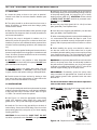
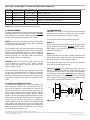
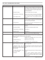
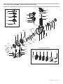
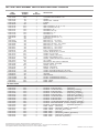
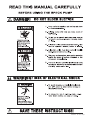
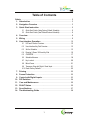
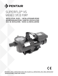
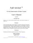
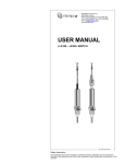
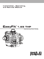
Installation, Operating,
and Service Manual
EasyFit
®
1.65 THP
Swimming Pool Pump
Table of Contents
1
Pump Manual
3-11
2
Motor Manual 12-43
Technical Support:
Address: Speck Pumps
8125 Bayberry Road
Jacksonville, FL. 32256
USA
Hours: (Monday - Friday) 8:00 am to 5:00 pm EST
Toll Free: 800-223-8538
Phone: 904-739-2626
Fax: 904-737-5261
Website: www.usa.speck-pumps.com
Email: [email protected]
Date of Installation:
Installed by:
Serial Number:
For Service Call:
Manufactured by Speck Pumps, Jacksonville Florida USA, ©All Rights Reserved.
This document is subject to change without notice.
Rev 02/2015
SAVE THESE INSTRUCTIONS!
OWNER’S MANUAL
Swimming Pool Pump
READ THIS MANUAL CAREFULLY
BEFORE USING THE SPECK PUMP
Important Notice: This manual contains important information about the installation, operation and safe
use of this product. This information should be given to the owner and/or operator of this equipment.
WARNING: This product must be installed and serviced by a qualified pool professional, and must conform to all
national, state, and local codes.
WARNING: Before installing this product, read and follow all warning notices and instructions which are included.
Failure to follow safety warnings and instructions can result in severe injury, death, or property damage. Call
(800) 223-8538 or visit www.usa.speck-pumps.com for additional copies of these instructions.
IMPORTANT SAFETY INSTRUCTIONS
When installing and using this electrical equipment,
basic safety precautions should always be followed,
including the following:
READ AND FOLLOW
ALL INSTRUCTIONS.
1.
2. WARNING - To reduce the risk of injury, do not
permit children to use this product unless they are
closely supervised at all times.
3. WARNING - Risk of Electrical Shock. Connect only
to a branch circuit protected by a ground-fault circuit
interrupter (GFCI). Contact a qualified electrician if
you cannot verify that a circuit is protected by a GFCI.
4. WARNING - To reduce the risk of electric shock,
replace any damaged cord immediately.
5. DO NOT install within an outer enclosure or beneath
the skirt of a hot tub or spa.
6. CAUTION - This pump is for use with permanentlyinstalled pools and may also be used with hot tubs
and spas if so marked. DO NOT use with storable
pools. A permanently-installed pool is constructed in
or on the ground or in a building such that it cannot
be readily disassembled for storage. A storable pool
is constructed so that it is capable of being readily
disassembled for storage and reassembled to its
original integrity.
7. The unit must be connected only to a supply circuit
that is protected by a ground-fault circuit-interrupter
(GFCI). Such a GFCI should be provided by the
installer and should be tested on a routine basis. To
test the GFCI, push the test button. The GFCI should
interrupt power. Push the reset button. Power should
be restored. If the GFCI fails to operate in this manner,
the GFCI is defective. If the GFCI interrupts power
to the pump without the test button being pushed, a
ground current is flowing, indicating the possibility of an
electric shock. Do not use this pump. Disconnect the
pump and have the problem corrected by a qualified
service representative before using.
8. TO REDUCE RISK OF ELECTRICAL SHOCK,
A copper bonding connector (8 AWG) is provided for
bonding the motor to all metal parts of the swimming
pool, spa, or hot tub structure and to all electrical
equipment, metal conduit, and metal piping within 5
feet of the inside walls of a swimming pool, spa, or
hot tub, when the motor is installed within 5 feet of the
inside walls of the swimming pool, spa, or hot tub.
NOTE: To installer and/or operator of the Speck
Swimming Pool Pump; the manufacturer’s warranty
will be voided if the pump is improperly installed and/
or operated.
SAVE THESE INSTRUCTIONS!
9.
SECTION 1 EQUIPMENT OPERATION AND MAINTENANCE
1/1 LOCATION
1. Locate the pump as close to the pool as practical.
Consult local codes for minimum distance between pool
and pump.
2. The piping should be as direct and free from turns or
bends as possible, as elbows and other fittings greatly
increase friction losses.
3. Place pump on a solid foundation which provides a rigid
and vibration-free support so that it is readily accessible for
service and maintenance.
4. Though the pump is designed for outdoor use, it is
advised to protect the pump from continuous direct heat.
Install the pump in a well ventilated location protected from
excessive moisture (flooding, sprinklers, rain downspouts,
etc.).
5. Protect the pump against flooding and excess moisture,
prevent foreign objects from clogging air circulation around
motor. All motors generate heat that must be removed by
providing proper ventilation.
6. DO NOT store or use gasoline or other flammable
vapors or liquids in the vicinity of this pump. DO NOT store
pool chemicals near the pump.
7. DO NOT remove any safety alert labels such as
DANGER, WARNING, or CAUTION. Keep safety labels
in good condition and replace missing or damaged labels.
8. Provide access for future services by leaving a clear
area around the pump. Allow plenty of space above the
pump to remove lid and basket for cleaning.
1/2 INSTALLATION
1. This pump is designed as a direct replacement for pumps
made by several manufacturers. It can also be installed as
a new pump with easy to connect unions. Refer to Figure
1 & Table 1 for various connection options.
4. Install the 70 x 6mm o-ring (part# 919) on the back of
the discharge fitting. Secure the discharge fitting to the top
of the pump casing (part# 101) using four (4) 6 x 22mm
tapping screws (part# 917). CAUTION: Screws should
be HAND TIGHT. DO NOT use drills or pneumatic tools.
DO NOT over tighten!
5. Insert the pump risers (part# 182.1 & 182.2) into base
plate (part# 894). See Exploded View.
6. Insert the motor supports (part #920/921) into the base
plate (part #894). See Exploded View.
7. When connecting pipework to pump with threaded ports
it is recommended that thread seal tape be used. If the
suction pipe is not sealed correctly, the pump will not prime
properly and will pump small volumes of water or none at
all.
8. When installing the pump, care should be taken to
see that the suction line is below water level to a point
immediately beneath and the pump to ensure quick priming
via a flooded suction line. The height between the pump
and the water level should not be more than five (5) feet.
BONDING: As required by National Electrical Code Article
680-22, the pump motor must be electrically bonded to
the pool structure (reinforced bars, etc.) by a solid copper
conductor not smaller than #8 AWG (8.4 mm2) wire via the
external copper bonding lug on the pump motor.
GROUNDING: Permanently ground the pump motor
using a conductor of appropriate size. Connect to the #10
green headed ground screw provided inside the motor
terminal box.
For more information about the motor operation
refer to the motor manual.
NOTE: DO NOT connect to electric power supply until the
unit is permanently grounded
2“ NPT
1 1/2“ NPT
6: W78.50.019
2. Use Figure 1 to select the appropriate suction fitting
(part# 153), discharge fitting (part# 156), pump risers
(part# 182.1 & 182.2), and motor supports (part# 920/921).
3. Install the 76 x 6mm o-ring (part #918) on the back of
suction fitting. Secure the suction fitting to the front of the
pump casing (part #101) using four (4) 6 x 22mm tapping
screws (part #917).
CAUTION: Screws should be HAND TIGHT. DO NOT
use drills or pneumatic tools. DO NOT over tighten!
6: W78.50.020
4: W78.50.008
3: W78.50.005
2: W78.50.007
1: W78.50.006
1: l = 2.85”
2: l = 1.97”
3: l = N/A
4: l = 3.13”
6: l = 1.97”
1: l = 6.08”
2: l = 5.10”
3: l = 3.72”
4: l = 6.32”
6: l = 5.10”
Figure 1.0 - Replacement Pump Connection Options
2999999319 - Rev. 0215 - EasyFit
SECTION 1 EQUIPMENT OPERATION AND MAINTENANCE
Option #
Suction Fitting
Discharge Fitting
Replaces Pump Model(s)
1
W78.50.006
1.5” or 2” NPT
Pentair® Ultra-Flow®
2
W78.50.007
1.5” or 2” NPT
Pentair® WhisperFlo® & IntelliFlo®
3
W78.50.005
1.5” or 2” NPT
Hayward® Super Pump® & Super Pump VS®, Pentair® SuperFlo®
4
W78.50.008
1.5” or 2” NPT
STA-RITE® Dura-Glas & Max-E-Glas™
6
W78.50.019
W78.50.020
STA-RITE® Dyna-Glas™
Table 1.0 - Replacement Pump Connection Options
NOTE: It is normal for a few drops of water to escape from
the mechanical seal from time to time. This is especially
true during the break-in period.
The mechanical seal may come worn and/or loose during
the course of time, depending on the running time and water
quality. If water continually leaks out, a new mechanical
seal should be fitted. After long periods of NOT operational
(seasonal storage, etc.), the pump must be checked for
ease of rotation while it is switched off.
WARNING: Before servicing the pump, switch off the
circuit breakers at the power source. Severe personal
injury or death may occur if the pump starts while your
hand is inside the pump.
Place a screwdriver, allen wrench or appropriate tool in the
end of the motor shaft and turn it clockwise. OR Remove
the fan cover and turn the fan in a clockwise direction
manually. This may require removal of the cover at the rear
of the motor or small circular cap at the rear center of the
motor.
To Replace the Mechanical Seal
To replace the mechanical seal, remove the sixteen (16)
bolts holding the casing to the seal housing. Slide the
motor part including the seal housing out. Remove the
terminal cover from the rear of the motor and secure the
center motor shaft with a 1/2” wrench. Remove impeller
nut by turning it counter-clockwise when facing it. Pull the
impeller from the motor shaft noting the position of the seal.
Remove the seal from the impeller shaft. To re-assemble,
reverse the process. Use only water as a lubricant to
install both sides of the seal. Make sure both sides of the
seal (ceramic and spring portion) are clean. Gently wipe
polished faces with soft and dry cotton cloth. Surfaces can
easily be damaged by dirt and scratching. (Use a drop of
loc-tite to secure the impeller nut.)
1/4 WINTERIZING
CAUTION: The pump must be protected when freezing
temperatures are expected. Allowing the pump to freeze
will cause severe damage and void the warranty.
There are two options when winterizing the pump:
Option 1:
Drain all the water from the pump, system equipment, and
piping. Remove drain plug(s). DO NOT replace plug(s).
Store plug(s) in the strainer basket for winter. Keep the
motor covered and dry.
Option 2:
Drain all the water from the pump, system equipment, and
piping. Remove the pump and motor from the plumbing
and store indoors in a warm and dry location.
NOTE: When the winter season is over the pump will need
to be check and primed prior to start.
CAUTION: DO NOT run the pump dry. If the pump is run
dry, the mechanical seal will be damaged and the pump
will start to leak at the seal. If this occurs, the mechanical
seal will need to be replaced. ALWAYS maintain the proper
water level in your pool. Continued operation in this manner
could cause a loss of pressure, resulting in damage to the
pump casing, impeller, and mechanical seal.
Ceramic Ring
Rubber Collar
Pump Seal Housing
1/3 MAINTENANCE
The pump requires little or no service other than reasonable
care and periodic cleaning of the strainer basket. DO NOT
strike basket to clean. When cleaning the basket inspect
the lid o-ring for damage and replace if necessary.
Impeller
Shaft
Spring
Assembly
Sealing
Surfaces
Figure 2.0
Hayward® and Super Pump® are registered trademarks of Hayward Industries, Inc.
Pentair®, SuperFlo®, WhisperFlo®, IntelliFlo®, Ultra-Flow®, Sta-Rite®, Dyna-GlasTM, Dyna-Pro®, Dura-Glas, and Max-E-GlasTM are trademarks and/or registered trademarks of Pentair Water Pool and
Spa, Inc. and/or its affiliated companies.
2999999319 - Rev. 0215 - EasyFit
SECTION 2 TROUBLESHOOTING GUIDE
PROBLEM
1. Pump will not prime.
2. Motor does not turn.
3. Low flow.
POSSIBLE CAUSES
SOLUTION
a. Suction air leak.
Make sure the see-through lid and o-ring are clean
and properly positioned. Tighten see-through lid (hand
tight). Tighten all pipes and fittings on suction side of
the pump. Be sure water in the pool is high enough to
flow through skimmer.
b. No water in pump.
Make sure strainer tank is full of water.
c. Closed valves or blocked lines.
Open all valves in system. Clean skimmer and strainer
tank. Open pump and check for clogging of impeller.
d. Low voltage to motor.
Check voltage at motor. If low, pump will not come up
to speed.
a. No power to motor.
Check that all power switches are on. Be sure fuse
or circuit breaker is properly set. Time set properly?
Check motor wiring at terminals.
b. Pump jammed.
With power off, turn shaft. It should spin freely. If not,
disassemble and repair.
a. Dirty filter.
Back wash filter when filter pressure is high, or clean
cartridges.
b. No skimmer basket.
Clean skimmer and pump strainer basket.
c. Closed valves or blocked lines.
See problem 1.
d. Suction air leak.
See problem 1.
4. Noisy operation of motor.
a. Bad bearings.
Noise when shaft is turned up by hand. Motor is hot in
bearing area when running. Replace bearing.
5. Motor runs hot.
These motors will run hot to the touch, however, this is normal. They are designed that
way. Thermal overload protector will function to turn them off if there is an overload or high
temperature problem. Excessive heat can be cause by:
6. Noisy operation of pump.
a. Low voltage.
Increase size of electrical wire. Be sure motor is
operating on correct voltage.
b. Installed in direct sun.
Shield motor from sun’s rays.
c. Poor ventilation.
Do not tighten cover or enclosure motor.
a. Air leak in suction line. Bubbles Repair leak. Check suction pipe, see-through lid in
in water returning to pool at inlet. place? O-ring clean?
b. Restricted suction line due Remove blockage or increase suction pipe size. Make
to blockage or under size pipe. sure strainer tank is clean. Are all suction valves fully
Indicated by high vacuum reading open?
at pump suction.
c. Foreign matter (gravel, metal, Disassemble pump and remove foreign matter from
etc.) in pump impeller.
impeller.
d. Cavitation.
Improve suction conditions. (Reduce suction life,
reduce number of fittings, increase pipe size.) Increase
discharge pressure and reduce flow by throttling
discharge valve.
2999999319 - Rev. 0215 - EasyFit
SECTION 2 TROUBLESHOOTING GUIDE - continued
PROBLEM
POSSIBLE CAUSES
SOLUTION
7. Motor overload protection a. Motor is not connected properly. Check wiring diagram on motor.
“kicks out”.
b. Low voltage due to under size Check with volt meter. Increase size of supply wire.
wire or low incoming voltage.
Reports low supply voltage to power company. Voltage
at motor must be within 10% of motor nameplate
voltage.
c. Wrong size heaters in protective Heaters should be one size larger than full load amps
device.
shown on motor nameplate.
d. Overload due to binding in pump Indicated by high amperage readings on motor,
or wrong size impeller.
binding shaft. Disassemble unit and correct.
SECTION 3 SERVICING INFORMATION
When calling the manufacturer regarding a question or
problem with your pump, please have the serial number
available.
The serial number is located on the pump either on the
casing and/or motor. Replacement parts may be available
from your installer.
SECTION 4 LIMITED WARRANTY
Speck Pumps-Pool Products, Inc. grants solely to the original consumer purchaser (“Buyer”) of the pump and motor the
following personal, non-transferable and limited warranty on the following terms and conditions (the “Limited Warranty”): the
pump and motor is warranted to be free of material defects in materials or workmanship under normal use for a period of two
(2) year beginning on the date of the Buyer’s purchase of the pump and motor. Not withstanding any provisions herein to the
contrary, the warranties and obligations hereunder shall not in any event extend for more than three (3) years beyond the
date of shipment of the pump and motor from the factory (the “Limited Warranty Period”). The Limited Warranty is subject to
each of the following additional terms and conditions:
1. IN THE EVENT OF ANY BREACH OF THE LIMITED WARRANTY, SPECK PUMPS - POOL PRODUCTS, INC.’S
ENTIRE OBLIGATION AND LIABILITY TO BUYER, AND BUYER’S SOLE AND EXCLUSIVE REMEDY SHALL BE AS
FOLLOWS: Speck Pumps - Pool Products, Inc. will, at its option, either repair or replace the pump and motor or refund to
Buyer the purchase price actually paid by Buyer for the pump and motor subject to the Limited Warranty. Speck Pumps
- Pool Products, Inc. shall have no obligations under the Limited Warranty unless Buyer delivers timely written notice to
Speck Pumps - Pool Products, Inc. of the Limited Warranty claim within the Limited Warranty Period and returns the pump
and motor to Speck Pumps - Pool Products, Inc. if requested. To the fullest extent permitted by law, Speck Pumps - Pool
Products, Inc. expressly disclaims any liability for, and the Limited Warranty does not include or cover, any labor, costs or
other expenses in connection with the removal, transportation, shipment, insurance, replacement, repair, or installation of
repaired or replaced parts or for any other costs or expenses or damages to property or things including, but not limited to,
those arising in connection with the use of, or inability to use, the pump and motor.
2. To the fullest extent permitted by law, the Limited Warranty will be void and of no force or effect and Speck Pumps - Pool
Products, Inc. will have no liability, responsibilities or obligations to Buyer or with respect to the pump and motor in the event
of the occurrence of any one or more of the following:
(a) Any damage to the pump and motor caused by Buyer, any third party, ground movement, other natural forces, acts of
God or any other sources or causes not arising from a breach of the Limited Warranty, excluding ordinary wear and
tear;
(b) Any replacement, modification, alteration or repair of any parts or components of the pump and motor by anyone
other than Speck Pumps - Pool Products, Inc.;
(c) Any abuse, misuse, accident, tampering with, improper installation or modification of the pump and motor or any other
actions, inactions or failures to act that violate the terms and conditions of this Limited Warranty;
2999999319 - Rev. 0215 - EasyFit
SECTION 4 LIMITED WARRANTY - continued
(d) Buyer’s failure or inability to present an invoice, bill, receipt or other documentation clearly evidencing that the pump
and motor was installed and maintained in strict compliance with this Limited Warranty and that the claim was timely
submitted within the Limited Warranty Period; and/or
(e) Buyer’s failure to comply with the conditions and contingencies set forth in paragraph 3 below.
3. The Limited Warranty is expressly conditioned and contingent upon Buyer’s strict compliance with each of the following:
(a) Installation of the pump and motor by an experienced and qualified pool industry professional and a licensed electrician
who is licensed within the jurisdiction in which the pump and motor is installed and will be used; and
(b) Buyer’s operation and maintenance of the pump and motor in strict accordance with Speck Pumps - Pool Products,
Inc.’s printed operator/maintenance manuals delivered with the pump and motor.
4. DISCLAIMER: THE LIMITED WARRANTY IS THE ONLY WARRANTY MADE AND IS IN LIEU OF ALL OTHER
WARRANTIES, AND ANY AND ALL IMPLIED WARRANTY OR CONDITION OF MERCHANTABILITY, THE IMPLIED
WARRANTY AGAINST INFRINGEMENT, AND THE IMPLIED WARRANTY OR CONDITION OF FITNESS FOR A
PARTICULAR PURPOSE ARE EXPRESSLY LIMITED IN THEIR SCOPE AND DURATION TO THE TWO YEAR TERM
OF THE LIMITED WARRANTY SET FORTH HEREIN. SOME STATES DO NOT ALLOW LIMITATIONS ON HOW LONG
AN IMPLIED WARRANTY LASTS, SO THE ABOVE LIMITATION MAY NOT APPLY TO THE BUYER.
5. TO THE FULLEST EXTENT PERMITTED BY LAW, IN NO EVENT SHALL SPECK PUMPS - POOL PRODUCTS, INC.
OR ITS OFFICERS, DIRECTORS, EMPLOYEES, SHAREHOLDERS, AGENTS, OR REPRESENTATIVES BE LIABLE
FOR ANY SPECIAL, INDIRECT, INCIDENTAL, EXEMPLARY OR CONSEQUENTIAL DAMAGES OR LOSS, INCLUDING
TIME, MONEY, GOODWILL, AND LOST PROFITS IN ANY WAY WHICH MAY ARISE HEREUNDER OR FROM THE
USE OF OR INABILITY TO USE THE PUMP AND MOTOR OR THE PERFORMANCE OR NONPERFORMANCE OF
ANY OBLIGATION UNDER THIS LIMITED WARRANTY. THIS PARAGRAPH, THE WARRANTY DISCLAIMERS
IN PARAGRAPH 4 ABOVE, AND THE SOLE AND EXCLUSIVE REMEDY SET FORTH IN PARAGRAPH 1 ABOVE
SHALL APPLY EVEN IF SPECK PUMPS - POOL PRODUCTS, INC. HAS BEEN NOTIFIED OF THE POSSIBILITY OR
LIKELIHOOD OF SUCH DAMAGES OCCURRING, WHETHER SUCH LIABILITY IS BASED ON CONTRACT, TORT,
NEGLIGENCE, STRICT LIABILITY, PRODUCTS LIABILITY OR OTHERWISE, AND EVEN IF ANY REMEDY STATED
HEREIN FAILS OF ITS ESSENTIAL PURPOSE. SOME STATES DO NOT ALLOW THE EXCLUSION OR LIMITATION
OF SPECIAL, INDIRECT, INCIDENTAL, EXEMPLARY OR CONSEQUENTIAL DAMAGES OR LOSS, SO THE ABOVE
EXCLUSIONS AND LIMITATIONS MAY NOT APPLY.
6. This Limited Warranty gives the Buyer specific legal rights, and the Buyer may also have other rights, which vary from
state to state.
7. A return merchandise authorization (“RMA”) must be obtained from Speck Pumps - Pool Products, Inc. before returning
any product. Products returned without an RMA will be refused and returned, unopened, to the Buyer. All returned products
are to be sent freight prepaid and insured for Buyer’s protection to the manufacturer at 8125 Bayberry Road, Jacksonville,
Florida 32256. Under no condition will products be accepted after the expiration of the Limited Warranty Period. Speck
Pumps - Pool Products, Inc. shall not bear any costs or risks incurred by Buyer in shipping a defective pump and motor to
Speck Pumps - Pool Products, Inc. or in shipping a repaired or replaced pump and motor to Buyer.
Technical Support:
Address: Speck Pumps
8125 Bayberry Road
Jacksonville, FL. 32256 USA
Hours: Toll Free: Phone: Fax: Website: (M-F) 8:00 am - 5:00 pm EST
800-223-8538
904-739-2626
904-737-5261
www.usa.speck-pumps.com
Date of Installation:
Installed by:
Serial Number:
For Service Call:
Manufactured by Speck Pumps, Jacksonville Florida USA, ©All Rights Reserved.
This document is subject to change without notice.
2999999319 - Rev. 0215 - EasyFit
SECTION 5 REPLACEMENT PARTS & EXPLODED VIEW
160.2
ER
IR
OUVR
FERM
156.1
SE
CLO
ZU
OPEN
AUF
917
721
156.2
412.1
917
143
156
156.3
160.1
919
919
Alternate Discharge Fittings
412.5
412.2
174.2
918 153 917
721
161.2
113
900
903
412.4
502
507
800
230
914.2
433
554.2
182.1
921
101
130
182.2
Alternate Suction Fittings
917 153.6
153.4 153.3
153.2
153.1
917
894
920
2999999319 - Rev. 0215 - EasyFit
SECTION 5 REPLACEMENT PARTS & EXPLODED VIEW - continued
PART
NUMBER
DRAWING
NUMBER
QTY
REQUIRED
2921116022
2901410122
2901413002
2901411304
2901489400
2901416102
2901416103
2901417421
2921317421
2901417422
2901417420
2920750200
2901450700
TBD
2901423015
2901423009R
2901423009
2901423016
2901423017
2901423013
2923591201
2920141240
2921141210
2901441210
2920141210
2991000091
2901116010
2920343310
2920110200
2991400028
2901414303
5879006022
2901441270
2901441282
2902089420
2920889410
2901415300A
2901415600A
2901418213
2901418223
160.2
101
130
113
894
161.2
161.2
174.2
174.2
174.2
174.2
502
502
230
230
230
230
230
230
230
903
412.4
412.1
412.2
412.5
900
160.1
433
598
914.2
143
917
918
919
920
921
153
156
182.1
182.2
1
1
2
1
1
1
1
1
1
1
1
1
1
1
1
1
1
1
1
1
1
1
1
1
1
10
1
1
1
4
1
8
1
1
1
7
1
1
1
2
LOCK RING WITH HANDLES - LID
CASING
NAME PLATE - ORANGE
FLANGE
BASE
SEAL HOUSING (-I, -II, -IV, -V, -VI)
SEAL HOUSING (1.65, -III)
DIFFUSER (-I, -II)
DIFFUSER (1.65, -III)
DIFFUSER (-IV, -V)
DIFFUSER (-VI)
FLOATING EYE SEAL (-I, -II)
FLOATING EYE SEAL (-IV, -V)
IMPELLER (-I)
IMPELLER (-II) 113 / 5.3mm
IMPELLER (-III) 118 / 5.0mm
IMPELLER (1.65 THP) 124 / 5.0mm
IMPELLER (-IV) 120 / 8.7mm
IMPELLER (-V) 120 / 10.0mm
IMPELLER (-VI) 120 / 7.8mm
PLUG - CASING DRAIN (1/4”)
O-RING - DRAIN PLUG 11 x 2.5mm
O-RING - LID 137 x 5mm
O-RING - CASING 206 x 6mm
O-RING - DIFFUSER 90 x 5mm
SCREW - CASING HEX/SLOT M7 x 48mm SS
LID - CLEAR
MECHANICAL SEAL (20mm) COMPLETE
MOTOR FLANGE - 56 FRAME
SCREW - 3/8”-16 x 2”
BASKET - ONE PIECE
SCREW - 6 x 22mm, A2
O-RING - SUCTION FITTING (ALL) 76 x 6mm
O-RING - DISCHARGE FITTING (ALL) 67 x 6mm
ADAPTER
LEGO SPACER
FITTING - STANDARD SUCTION KIT
FITTING - STANDARD DISCHARGE KIT
RISER - FRONT
RISER - REAR
153.1
153.1
153.2
153.2
153.3
153.3
153.4
153.4
153.6
156.1
156.2
156.3
182.1
182.1
182.1
182.2
182.2
182.2
182.2
1
1
1
1
1
1
1
1
1
1
1
1
1
1
1
2
2
2
2
FITTINGS - 1.5” NPT SUCTION
(Ultra-Flow®)
FITTINGS - 2” NPT SUCTION
(Ultra-Flow®)
FITTINGS - 1.5” NPT SUCTION
(WhisperFlo® / IntelliFlo®)
FITTINGS - 2” NPT SUCTION
(WhisperFlo® / IntelliFlo®)
FITTINGS - 1.5” NPT SUCTION
(Super Pump® / SuperFlo®)
FITTINGS - 2” NPT SUCTION
(Super Pump® / SuperFlo®)
FITTINGS - 1.5” NPT SUCTION
(Dura-Glas / Max-E-GlasTM)
FITTINGS - 2” NPT SUCTION
(Dura-Glas / Max-E-GlasTM)
FITTINGS - 2” NPT SUCTION
(Dyna-GlasTM)
FITTINGS - 1.5” NPT DISCHARGE (Pentair®, Hayward®, STA-RITE®)
FITTINGS - 2” NPT DISCHARGE (Pentair®, Hayward®, STA-RITE®)
FITTINGS - 2” NPT DISCHARGE
(STA-RITE® Dyna-GlasTM)
RISER - FRONT
(Ultra-Flow®)
RISER - FRONT
(WhisperFlo® / IntelliFlo® / Dyna-GlasTM)
RISER - FRONT
(Dura-Glas / Max-E-GlasTM)
RISER - REAR
(Ultra-Flow®)
RISER - REAR
(WhisperFlo® / IntelliFlo® / Dyna-GlasTM)
RISER - REAR
(Super Pump® / SuperFlo®)
RISER - REAR
(Dura-Glas / Dyna-GlasTM)
DESCRIPTION
OPTIONAL PARTS
2901415306
2901415316
2901415307
2901415317
2901415305
2901415315
2901415308
2901415318
2901415323
2901415602
2901415612
2901415623
2901418212
2901418213
2901418214
2901418222
2901418223
2901418221
2901418224
Hayward® and Super Pump® are registered trademarks of Hayward Industries, Inc.
Pentair®, SuperFlo®, WhisperFlo®, IntelliFlo®, Ultra-Flow®, Sta-Rite®, Dyna-GlasTM, Dyna-Pro®, Dura-Glas, and Max-E-GlasTM are trademarks
and/or registered trademarks of Pentair Water Pool and Spa, Inc. and/or its affiliated companies.
2999999319 - Rev. 0215 - EasyFit
2999999319 - Rev. 0215 - EasyFit
v
165
VARIABLE SPEED USER MANUAL
Premium Efficiency Variable Speed Motor
COPYRIGHT
Copyright 2013, Regal Beloit America, Inc.
Tipp City, Ohio. All rights reserved.
TRADEMARKS
All trademarks and registered trademarks® are the property of their
respective companies. The information in this document incorporates
proprietary rights and is not to be duplicated wholly or in part without
the express written permission of Regal Beloit Corporation and / or
Regal Beloit America, Inc.
June 2013/USA
v
Table of Contents
Safety ..................................................................................................... 2
1. Introduction ................................................................................... 3
2. Navigation Overview ..................................................................... 3
3. Quick Start Instruction ................................................................. 5
3.1 QuickStartGuide(UsingFactoryDefaultSchedule) ........................ 5
4.
5.
6.
3.2 QuickStartGuide(UserDefinedCustomSchedule) ........................ 6
Overview ........................................................................................ 8
Wiring ............................................................................................ 9
User Interface Operation ............................................................ 12
6.1 LEDandFunctionOverview ..................................................... 12
6.2 UserInterfaceKeyPadOverview .............................................. 13
6.3 SettheSchedule ................................................................... 13
6.4 RunningV-Green165fromKeyPad .......................................... 15
6.5 OVERRIDE .......................................................................... 17
7.
6.6 ScheduleAdvance ................................................................. 18
6.7 KeyLockout ......................................................................... 20
6.8 MotorPause ......................................................................... 21
6.9 TemporaryStopwithDigital/SerialInput .................................... 21
6.10 ResetFactoryDefaults ............................................................ 22
Priming ......................................................................................... 22
8.
9.
10.
11.
Freeze Protection ........................................................................ 22
Control with Digital Inputs ......................................................... 23
DIP Switches ................................................................................ 24
Care and Maintenance ................................................................ 25
12. FAULT Status ............................................................................... 25
13. Specifications .............................................................................. 27
14. Troubleshooting Guide ............................................................... 28
1
v
SAFETY
Safety is emphasized throughout this user manual. These are safety
alert symbols and signal words. They alert the user to potential personal injury hazards. Obey all safety messages to avoid possible injury
or death or damage to equipment and other property.
DANGER
DANGER
DANGER indicates a hazardous situation which, if not avoided, will
result in death or serious injury.
WARNING
WARNING indicates a hazardous situation which, if not avoided, could
result in death or serious injury.
CAUTION
CAUTION indicates a hazardous situation which, if not avoided, could
result in minor or moderate injury.
NOTICE
NOTICE
NOTICE identifies potential equipment damage or failure conditions
and alerts personnel to potentially dangerous situations.
2
v
1
Introduction
The V-Green® 165 is a premium efficiency variable speed motor that
provides tremendous program flexibility in terms of motor speed
and time settings. The variable speed V-Green 165 is intended to
enable running at the lowest speeds needed to maintain a sanitary
environment, which in turn minimizes energy consumption. Pool size,
the presence of additional water features, chemicals used to maintain
sanitary conditions, and environmental factors will impact optimal
programming necessary to maximize energy conservation.
The V-Green 165 is for use with 208-230 Vrms nominal, and in pool pump applications
ONLY. Connection to the wrong voltage, or use in other application may cause damage
to equipment or personal injury.
The integrated electronics interface controls the speed settings as
well as the run durations. The V-Green 165 can run at speeds ranging
between 600 and 3450 RPM and is rated for 208-230 Vrms at an input
frequency of 60 Hz.
2
Navigation Overview
➢
➢
+, - Increases/decreases selected value
Pressing any key following a change accepts the current value
displayed inside the setting
Active Step LEDs (4x)
Programming Buttons (4x)
Speed LED
Power LED
Duration LED
Fault LED
Bar Graph
Stop Button
+/- Buttons
Start Button
Figure 1: V-Green 165 User Interface Button Descriptions
3
v
If power is connected to the V-Green 165 motor, pressing any of the following buttons
referred to in section 2 could result in the motor starting. Failure to recognize this could
result in personal injury or damage to equipment.
Note: The START button must be pressed for the V-Green 165 to
operate. The START LED will illuminate after the button has been
pressed indicating the V-Green 165 is capable of operating. Pressing
the stop button will turn off the START LED and stop the motor if
running.
V-Green 165 Features
• Simple user interface
• Digital inputs for compatibility with pool automation systems
• Motor design reduces noise emissions
• UV and rain-proof enclosure
• Freeze Protection
• Manual OVERRIDE
• Compatibility w/ V-Green 270 user interface
(soldasaseparateaccessory)
• High efficiency electromechanical motor and control design
Benefits of adding an optional V-Green 270
user interface with the V-Green 165 motor
• Ability to conduct field troubleshooting (i.e., view FAULT codes and
real time operating parameters).
• Ability to set a pump running schedule based on a real clock setting
(i.e., must input actual time which then determines pump start and
stop times).
• Ability to remotely mount the V-Green 270 user interface (provides
easy access of user interface depending on pump location).
• Ability to configure prime speed and prime duration.
4
v
• Ability to configure freeze protection temperature.
• Ability to view actual speed and power of the V-Green 165 in real time.
• Ability to adjust the V-Green 165 motor speed in 25 RPM
increments (to fine tune flow for certain pool installations).
• Battery backup to store time setting.
3
Quick Start Instruction
If power is connected to the V-Green 165 motor, pressing any of the following buttons
referred to in section 3 could result in the motor starting. Failure to recognize this could
result in personal injury or damage to equipment.
3.1
Quick Start Guide (Usingthefactorydefaultschedule)
The following table describes the factory default settings for DURATION
and SPEED order:
Button
Duration
(In Hours)
Speed
(In RPM)
STEP 1
4
3100
STEP 2
4
2600
STEP 3
8
1600
OVERRIDE
2
3450
Pressing the START key will start the V-Green 165 based on the factory
default schedule.
NOTE: If power is cycled to the V-Green 165 and the user does not
press the STOP key, the V-Green 165 will automatically start and
run the programmed default schedule shown in the chart above. This
feature ensures that the V-Green 165 will re-start in the event of a
power outage.
5
v
3.2
Quick Start Guide (User-definedcustomschedule)
A V-Green 165 user can set the program DURATION and SPEED for
STEP 1, STEP 2, STEP 3 & OVERRIDE keys.
NOTE: V-Green 165 must be Stopped (Press STOP Key) for programming DURATION and SPEED of the STEP 1, STEP 2, and STEP 3
keys. OVERRIDE DURATION and SPEED can be programmed when
the V-Green 165 is either stopped or running.
Press the STEP 1 key. The STEP 1 button and DURATION setting
LEDs will illuminate. The bar graph will show default DURATION for
STEP 1.
1. Press UP (+) or DOWN (-) arrows to change the DURATION
2. Press the STEP 1 key again to change the SPEED setting.
The SPEED setting LED will illuminate. The bar graph will
show default SPEED for STEP 1.
3. Press UP (+) or DOWN (-) arrows to change the SPEED.
4. Press any STEP or OVERRIDE key to save the DURATION
and SPEED settings for STEP 1. If the user decides not to
save the settings, pressing the STOP key will revert back to the
previously stored setting.
6
v
5. Press STEP 2, STEP 3, or OVERRIDE key. Repeat steps 1- 4
to program the corresponding DURATION and SPEED for each
button.
6. Press START to run the V-Green 165 based on the programmed 24 hour schedule.
7. Pressing the STOP button will stop the V-Green 165.
NOTE: The V-Green 165 can only be set to operate on a 24-hour
schedule. If a user attempts to program a schedule with a combined
duration for all three steps greater than 24 hours, the V-Green 165
software will retain the current STEP time duration only, and will zero
out the other two STEP time settings. As an example, if STEP 1 equals
eight (8) hours, STEP 2 equals nine (9) hours, and STEP 3 equals eight
(8) hours – for a combined 25 hours – the V-Green 165 will retain the
setting for the current Step being programed and zero out the remaining two. For details regarding the set-up of the three steps as part of a
24-hour schedule, see section 6.
7
v
4
Overview
NOTICE
The V-Green 165 can and should be optimized to suit individual pool conditions. Specific
conditions including pool size, other devices, features, and environmental factors can
all impact the optimal settings.
Program customization may require some trial-and-error to determine
the most satisfactory settings as dictated by the conditions. In all cases,
setting the V-Green 165 at the lowest speed for the longest duration is
the best strategy to minimize energy consumption. However, conditions
may require running the V-Green 165 at a higher speed for some duration of time each day to maintain proper filtration to achieve satisfactory
sanitation.
The User Interface is located on top of the V-Green 165. To the right of
the STEP buttons is the OVERRIDE button. This button can be used
to operate the V-Green 165 at speeds outside of the normal operating
schedule.
Digital Inputs
Serial Connector
Keypad Buttons
DIP Switch
Mains Connections
Figure 2: V-Green 165 Overview
8
v
5
Wiring
The V-Green 165 controller must be wired according to the locally adopted version of the
NEC. A licensed, qualified electrician should complete the wiring for this product. Failure
to comply with this may result in death, serious personal injury or property damage.
The V-Green 165 controller must be wired according to the locally
adopted version of the NEC. A licensed, qualified electrician should
complete the wiring for this product.
The controller is designed to operate with 208-230 Vrms, single phase
power.
The V-Green 165 is designed to handle either a bare wire connection or
a quick disconnect connection. The quick disconnect tab is 0.250” and
will handle any commonly available mating connectors. For a direct wire
connection, the wire insulation should be stripped to a length of approximately 0.33.” The terminal block is capable of handling solid or stranded
wire up to 12 AWG in size. The screw for the mains connections should
be properly tightened to a torque value of 10 in-lb.
Pin #
Wire Color
Description
L1
Black
Hot 1
L2
Red or White
Hot 2
Green screw
Green
Earth
Table 1: Mains Connection
Pin #
Wire Color
Description
J201 - 1
Red
+12V
J201 - 2
Black
A
J201 - 3
Yellow
B
J201 - 4
Green
COM
Table 2: Communication Connection
9
v
Power should be turned off when installing, servicing, or repairing electrical components.
Observe all warning notices posted on the existing equipment, V-Green 165, and in
these installation instructions.
EARTH
L2
(RED OR WHITE)
L1
(BLACK)
208-230V POWER
SOURCE
Figure 3: Mains Connection Diagram
10
EARTH
v
V-Green 165 Controller
Automation System or
Solar System Controller
UI DIGITAL
INPUT CONNECTOR
J202
STEP 1
(pin 1)
STEP 2
(pin 2)
STEP 3
(pin 3)
EXTERNAL SUPPLY
Vac or
VDC
GND
OVER RIDE
(pin 4)
COMMON
(pin 5)
External Supply Range:
18-30V AC (24V AC+/- 20%)
9-30V DC (12/24V DC +/- 20%)
Figure 4: Wiring Diagram for Digital Inputs
Access to these terminals is in close proximity to the mains connectors which carry line
voltage capable of causing personal injury or damaging the equipment if contact is made.
Power should be turned off when accessing this area.
Figure 5: Digital Input connector
11
v
6
6.1
User Interface Operation
LED andV-Green
Function
Overview
165 165
UI LED
Indication
andand
respective
functionalities
V-Green
UI LED
Indication
respective
functionalities
Key for LEDs
Key for LEDs
X Solid N Indication
X OSolid ON Indication
@ 1 s@
ec 1 sec
* Blinking * Blinking between DURATION and SaPEED
** Alternates between DURATION nd SPEED
** Alternates for three imes t@
1 s@
ec 1 sec
# Blink for tthree imes # Blink LED →LED →
Function ↓ ↓
Function SPEED SPEED DURATION DURATION PowerPower STARTSTART FAULTFAULT STEP1STEP1 STEP2STEP2 STEP3STEP3 OVERRIDE
BARGRAPH
OVERRIDE
BARGRAPH
SETTING
SETTING SETTING
SETTING
Power Power On On
X
X
Step1Step1
X
X
X
X
Step2Step2
X
X
X
X
Keypad Functions
Keypad Functions
Step3Step3
X
X
X
X
Override
Override
X
X
X
X
X
X
X
X
X
X
X
Keypad lock lock
Keypad X
X
*
*
*
*
*
*
Keypad UnlockUnlock
Keypad X
X
X
X
X
X
X
X
Schedule Advance
Schedule Advance
X
X
Restore Default settings
Restore Default settings
X
X
Motor Motor pausepause
X
X
Temporary stop stop
Temporary X
X
DI1 ODI1 N ON
X
X
DI2 ODI2 N ON
X
X
DI3 ODI3 N ON
X
X
DI4 ODI4 N ON
X
X
*
X
** **
** **
** **
** **
** **
** **
** **
** **
** **
** **
** **
** **
X
*
X
X
X
# (All # LED)
(All LED)
*
*
*
*
X
X
X
X
* (0 R* PM)
(0 RPM)
Digital Digital Input IFnput unctions
Functions
*
*
*
*
*
*
*
*
X
X
X
X
X
X
X
X
X
X
X
X
X
X
X
X
X
X
X
X
Serial Serial Communication Functions
Communication Functions
Serial Serial Communication
Communication
X
X
*
*
Motor Motor spinning
spinning
X
X
*
*
Freeze Protection
Freeze Protection
Freeze Protection
Freeze Protection
X
*
X
Fault Fault Handling
Handling
UI fault
UI fault
X
X
*
*
Controller fault fault
Controller X
X
X
X
Figure 6: LED Functionality Table
12
*
v
6.2
User Interface Key Pad Overview
If power is connected to the V-Green 165 motor, pressing any of the following buttons
referred to in this section 6.2 could result in the motor starting. Failure to recognize this
could result in personal injury or damage to equipment.
1.
2.
3.
4.
5.
6.
STEP 1 (Set Schedule)
STEP 2 (Set Schedule)
STEP 3 (Set Schedule)
OVERRIDE (Settings)
START
STOP
6.3
è DURATION and SPEED
è DURATION and SPEED
è DURATION and SPEED
è DURATION and SPEED
Set the Schedule
If power is connected to the V-Green 165 motor, pressing any of the following buttons
referred to in this section 6.3 could result in the motor starting. Failure to recognize this
could result in personal injury or damage to equipment.
Set the DURATION and SPEED for the V-Green 165 using the keys on
the User Interface. The schedule is based on a 24-hour schedule and
will repeat each day of the week.
The highest speed rating for the V-Green 165 is 3450 RPM and the
lowest is 600 RPM. Unless a new user-defined schedule is entered, the
V-Green 165 will operate based on the following factory default schedule:
13
v
Button
Duration
(In Hours)
Speed
(In RPM)
STEP 1
4
3100
STEP 2
4
2600
STEP 3
8
1600
OVERRIDE
2
3450
Table 3: Factory default schedule
Schedule Tables
Use the tables below to record a personalized operating schedule.
Recording the planned schedule in the table below will make the programming process easier and will help the user remember the custom
settings in case of inadvertent loss of schedule. The user interface will
not allow the user to program an overlap between different STEPs of the
schedule. The STEP currently being set will always take priority over
any previous settings. In the event a user attempts to program with a
combined duration greater than 24 hours, the current STEP setting will
be retained whereas the other two STEP settings will be cleared to zero
hours requiring the user to reset them. Prior to beginning the actual
programming process, it is advisable for the user to review the planned
schedule as outlined in chart form to ensure the cumulative duration is
not greater than 24 hours and no overlaps exist. It is always a good idea
to double check your programmed settings for accuracy once you have
completed the programming process.
Setup #1
Step 1
Step 2
Duration
Speed
14
Step 3
v
Setup #2
Step 1
Step 2
Step 3
Duration
Speed
Table 4: Custom Schedule
6.4
Running V-Green 165 from Keypad
If power is connected to the V-Green 165 motor, pressing any of the following buttons
referred to in this section 6.4 could result in the motor starting. Failure to recognize this
could result in personal injury or damage to equipment.
1. Press the START key and the V-Green 165 will run the programmed
24 hour duration schedule. The START event will be stored in the
controller. Should a power outage occur, the V-Green 165 will
automatically re-start at STEP 1 when power is restored.
2. The V-Green 165 will always run the PRIMING sequence when it
starts from the OFF state, including when it automatically restarts
following a power outage. The default Prime setting is defined in the
“Priming” section of this document.
3. The V-Green 165 then starts running in STEP 1 at the programmed
DURATION and SPEED. The “ACTIVE LED” for STEP 1 will turn
ON. The DURATION and SPEED setting LEDs along with the respective bar graph LED will blink back and forth every three (3)
seconds.
15
v
4. This sequence will then repeat for STEP 2 and then STEP 3 without the V-Green 165 stopping.
5. At the end of STEP 3, the V-Green 165 will wait if necessary for the
completion of the 24-hour schedule. During this waiting period (if
applicable), all of the “active step LEDs” will remain OFF. However,
the START LED will still be illuminated. After completion of the 24
hour schedule, the system restarts at STEP 1 and this cycle will
repeat indefinitely until the user presses the STOP key.
NOTE: Pressing a STEP key other than for the STEP currently running
will cause an immediate transition to the newly selected STEP. The
V-Green 165 will continue with the programmed schedule from that point
forward.
NOTE: If STOP is pressed during normal schedule operation, the 24
hour schedule will stop. When START is pressed again, the 24 hour
schedule will start from STEP 1.
NOTE: If power is lost while the V-Green 165 is running a 24 hour
schedule, upon restoration of power the V-Green 165 will start the 24
hour schedule from STEP 1.
NOTE: If a digital input (provided from an external source) is detected,
the V-Green 165 will start running on the STEP 1, STEP 2, STEP 3, or
OVERRIDE speed corresponding to the digital input. Upon removing
the digital input (provided from an external source), the V-Green 165 will
stop and the user will need to press START to begin the 24 hour schedule operation. However, if START was already pressed prior to receiving
a digital input, then the V-Green 165 will resume running the 24 hour
schedule once the digital input is removed.
NOTE: Pressing STOP at any time turns the V-Green 165 OFF and
clears the start time for the 24 hour schedule.
16
v
6.5
OVERRIDE
The V-Green 165 is equipped with an OVERRIDE feature, which can be
engaged to temporarily run at higher or lower speeds ranging between
600 to 3450 RPM. Once the OVERRIDE duration has elapsed, the VGreen 165 will automatically return to the programmed schedule.
1. Pressing the OVERRIDE key while the V-Green 165 is running will
cause the V-Green 165 to start running in the OVERRIDE mode
at the programmed DURATION and SPEED. The “active LED” for
OVERRIDE will illuminate. The DURATION and SPEED setting
LEDs along with its respective bar graph LED will blink back and
forth at three (3) second intervals.
2. The UP (+) / DOWN (-) arrows allow the user to configure OVER
RIDE DURATION and SPEED. These settings can be changed
while the V-Green 165 is running. These settings are stored each
time the UP (+) / DOWN (-) arrows are pressed.
NOTE: When the OVERRIDE duration ends, the V-Green 165 resumes
the 24 hour schedule at the point in the currently programmed 24 hour
schedule where it normally would be running at that time. The OVERRIDE duration will not affect the start or stop times of the 24 hour schedule. For example, if OVERRIDE runs during a period overlapping with a
later part of STEP 1 and an early part of STEP 2, the start time of STEP
3 is not affected.
17
v
NOTE: Pressing/Holding OVERRIDE key for more than three (3)
seconds will cancel OVERRIDE mode.
NOTE: During the OVERRIDE mode, the V-Green 165 will not start with
the priming sequence.
NOTE: It is recommended that you do not set the OVERRIDE duration
to 0 HRS. Setting the OVERRIDE duration to 0 HRS will not allow you
to change the duration setting while the motor is running. The motor will
have to be stopped in order to change the OVERRIDE settings if the
duration is set to 0 HRS.
6.6
Schedule Advance
DANGER
Do not perform any maintenance on the motor while the motor is in Schedule Advance
Mode. The motor may start without warning. This event could cause death or serious
personal injury.
The Schedule Advance mode allows the user to press the START button
at one time of the day, with the 24-hour schedule starting at a different
time of day. The V-Green 165 can run in the Schedule Advance mode
(by using the OVERRIDE button) and upon completion will begin the
programmed 24 hour schedule at STEP 1 DURATION and SPEED.
The following steps should be followed to set Schedule Advance mode:
1. With the V-Green 165 stopped,
press and hold the START key for
more than three (3) seconds. The
START LED will blink at a rate of one
second per pulse. The DURATION
setting LED and respective bar graph
LED will remain turned ON until the
Schedule Advance mode is complete.
18
v
2. Press the UP (+) or DOWN (-) arrows to set the desired delay
time after which the 24-hour schedule should start. The Schedule
Advance mode will automatically start after the desired delay time is
selected. The Schedule Advance mode can be canceled by pressing the STOP key.
NOTE: The OVERRIDE button will still function when the Schedule
Advance mode is active. This will allow the user to run the V-Green 165
during the period of the Schedule Advance mode.
NOTE: While the V-Green 165 is in the Schedule Advance mode, if a
user presses STEP 1, STEP 2, STEP 3 or the START key, the system
will start the normal schedule and the Schedule Advance mode will be
canceled.
NOTE: While the V-Green 165 is in the Schedule Advance mode, if a
user presses the STOP key, then the Schedule Advance mode is
canceled.
NOTE: If power is lost while the V-Green 165 is in the Schedule Advance
mode, then the 24-hour schedule will automatically start when power is
restored.
19
v
6.7
Key Lockout
Key lockout will not prevent the motor from being stopped by pressing the STOP button.
If the motor is operating in “key lockout” mode, and being controlled through a digital or
serial input, the motor will only temporarily stop (4 min.) it will then restart.
The V-Green 165 user interface has a “key lockout” feature to prevent
unwanted changes to the settings.
To lock the keys, hold down the ”STEP 1, STEP 2, and STEP 3” buttons
all at the same time for at least three seconds. The “active LEDs” for
STEP 1, STEP 2, and STEP 3 will blink for 30 seconds indicating that
the keypad is locked.
The user can unlock the keys by holding down the same three STEP
buttons for at least three seconds. The “active LEDs” for STEP 1, STEP
2, and STEP 3 will illuminate temporarily indicating the keypad is unlocked.
NOTE: While operating in “key lockout” mode the motor can still be
stopped by pressing the stop key. If no digital or serial input is present
the motor will remain stopped. If the motor is being controlled by a digital
or serial input the motor will only temporarily stop for 4 minutes. See
section 6.9 for more information on temporary stop.
20
v
6.8
Motor Pause
The V-Green 165 user interface has a “motor pause” feature that will
allow the user to temporarily stop the V-Green 165 for maintenance work
without disrupting the 24 hour schedule (i.e., for backwashing the filter).
If the V-Green 165 is currently running, the user can press and hold the
START button for more than three (3) seconds and the V-Green 165 will
stop and remain off until the user presses and holds the START button
again for more than three (3) seconds. The START and OVERRIDE
buttons will blink once every second indicating that the “motor pause”
feature is enabled. These LEDs will stop blinking once this feature is
canceled.
6.9
Temporary Stop with Digital / Serial Input
Temporary stop functionality only works while the V-Green 165 is being controlled by a
digital or serial input. If the motor is being controlled by the integrated key pad and STOP
is pressed, the motor will stop and remain stopped.
The V-Green 165 has a “temporary stop” feature that will immediately
stop the V-Green 165 when being controlled by a serial or digital input.
The user can press the STOP button while the V-Green 165 is running
and the V-Green 165 will stop and stay off for four (4) minutes. Once
this time has elapsed, the V-Green 165 will return to normal operation
and accept an input from digital or serial input source. Refer to section 9
for additional details on digital inputs.
NOTE: If the V-Green 165 is operating from serial or digital input, the
‘0 RPM’ LED of the bar graph will blink once every second indicating the
“temporary stop” feature has been activated. After the specified time
period, the V-Green 165 will return to normal operation and accept an
input from any digital or serial input source. Refer to section 9 for additional details on digital inputs.
21
v
6.10 Reset Factory Defaults
The V-Green 165 user interface has a “Reset to Factory Defaults”
feature to restore the schedule settings back to the original values
programmed at the factory. The user must press and hold the STOP
and OVERRIDE buttons for three (3) seconds to reset the settings back
to factory defaults. All of the UI bar graph LED’s will flash three (3) times
to confirm the settings were restored to factory defaults.
7
Priming
The V-Green 165 will always run the PRIMING sequence when starting
from the OFF state, except when starting in OVERRIDE. The factory
Prime settings are 2600 RPM for three (3) minutes.
8
Freeze Protection
NOTICE
The freeze protection function will NOT operate if the START button is not pressed. This
can be confirmed by verifying that the START LED is illuminated.
In the event that the outside air temperature drops below a set threshold,
the V-Green 165 will automatically turn on (assuming the START button
has been pressed) and circulate the pool water. The Freeze Protection
will run according to the following conditions (utilizing the factory default
settings):
Freeze Protection turn ON temperature = 39°F
Freeze Protection Duration = 8 Hours
By utilizing the V-Green 270 user interface (accessory sold separately)
these factory default settings can be changed.
Once this eight (8) hour period has elapsed, the V-Green 165 will check
the ambient temperature again. If the temperature is still below the
set threshold, the V-Green 165 will run for an additional 8 hours. If the
temperature is above the threshold, the V-Green 165 will automatically
return to the 24-hour based schedule.
22
v
9
Control with Digital Inputs
The user can run the V-Green 165 at the programmed STEP 1, STEP 2,
STEP 3, or OVERRIDE speeds by utilizing the four digital inputs. STEP
1, STEP 2, STEP 3, or OVERRIDE are equivalent to Digital Input 1, 2, 3
or 4 respectively.
NOTE: The controller is rated to accept digital inputs of 18V-30V AC
(24V AC+/- 20%) and 9-30V DC (12/24V DC +/- 20%).
NOTE: The V-Green 165 will detect either a 50/60Hz for AC input or an
active low signal for DC digital inputs.
The items below describe the functionality of the digital inputs:
1. If the user provides any one of the 4 digital inputs, then the
corresponding ACTIVE STEP LED will blink every one (1) second.
The SPEED LED and corresponding bar graph LED will be illuminated to indicate the Digital Input is functioning properly.
2. The START LED will be OFF when a digital input is present.
Access to these terminals is in close proximity to the mains connectors which carry line
voltage capable of causing personal injury or damaging the equipment if contact is made.
Power should be turned off when accessing this area.
NOTE: A generic wiring diagram is provided in figure 7 for connecting
the V-Green 165 to a “System Level Controller”. This concept can be
applied to a solar system or any other type of control system.
NOTE: There is no schedule for digital inputs. The timing for each
speed is controlled directly by the digital inputs.
NOTE: The digital inputs have the highest priority amongst all the inputs
(i.e., keypad, serial, or digital). Therefore the serial commands as well as
the User Interface inputs will be ignored when a digital input is present.
NOTE: If more than one digital input (switch) is present, then the VGreen 165 will give priority to the highest number digital input. Therefore OVERRIDE has highest priority followed by STEP 3, then STEP 2,
then STEP 1.
23
v
NOTE: If no digital input is detected, the V-Green 165 will automatically
start the 24 hour schedule if the START key was pressed prior to the
application of a digital input.
Access to these terminals is in close proximity to the mains connectors which carry line
voltage capable of causing personal injury or damaging the equipment if contact is made.
Power should be turned off when accessing this area.
System Level Control
Load
Relay1
Load
Relay2
Line
Relay3
Line
Load
Load
Relay4
Line
Line
Figure 7: System Level Control Wiring Diagram
10
DIP Switches
Access to these terminals is in close proximity to the mains connectors which carry line
voltage capable of causing personal injury or damaging the equipment if contact is made.
Power should be turned off when accessing this area.
The DIP switches can be used to configure different settings for the VGreen 165. Each DIP switch and their corresponding function is defined
in Table 5.
Switch #
Function
1
Power output on/off
2
Not Used
3
Not Used
4
Not Used
5
Not Used
Figure 8: DIP Switches
Table 5: DIP Switch Functions
24
v
11
Care and Maintenance
The V-Green 165 is both reliable and robust in harsh environments.
However, this product does contain electronics that are cooled by a fan
mounted to the V-Green 165. In order to ensure optimum reliability of
this product, it is recommended to clean the fan inlet on the back of the
V-Green 165 once a month. It is also important to keep this area free of
large debris such as leaves, branches, mulch, plastic bags, etc.
12
FAULT Status
While the FAULT LED is illuminated the motor will not run, upon clearing the fault, the
motor may automatically resume running depending on where in the schedule the FAULT
occurred. This may cause personal injury or damage to the equipment.
The paragraphs below illustrate the possible faults that can occur with
the V-Green 165. If the V-Green 165 does not restart automatically following the FAULT, cycle ac power to the V-Green 165 and wait five (5)
minutes. If this does not correct the situation, please contact Customer
Service at 1-800-262-6484.
The V-Green 165 reads the FAULT status and provides feedback to the
user via the FAULT LED. The V-Green 165 will illuminate the FAULT
LED when a FAULT is present. The V-Green 165 will stop and remain
OFF when the FAULT is present. Once the FAULT is cleared, if the VGreen 165 was previously running, it will automatically resume running
the normal schedule.
25
v
Below is the behavior of the FAULT LED when a FAULT is detected:
1.
When a FAULT is present, and the motor is not running,
only the FAULT LED and power LED will illuminate.
2.
When a FAULT is present, and the motor is running, then
the FAULT LED will illuminate. During the FAULT condition,
the bar graph LEDs on the interface will turn OFF. However,
the power LED, start LED & active STEP LED will remain
illuminated.
3.
When a FAULT is present and the FAULT LED is illuminated,
only the STOP key will function. The remaining buttons
become disabled.
4.
When the FAULT LED is continuously ON (i.e. not blinking), a
FAULT is present in the controller. When the FAULT LED is
blinking every one (1) second, a FAULT is present in the user
interface.
5.
When the FAULT has cleared, the FAULT LED will turn OFF.
6.
Once the FAULT is cleared, if the V-Green 165 was previously
running, it will automatically resume running the normal
schedule.
Please see Section 14 for troubleshooting issues and their resolutions.
26
v
13
Specifications
Overall Ratings
Input Voltage
Input Current
Input Frequency
Control Terminals
208 - 230 Vrms nominal
10.5 - 10.0 Arms
Single phase, 60 Hz
18-30V AC (24V AC+/- 20%) or
9-30V DC (12/24V DC +/- 20%)
N/A
1.65 THP (Total Horse Power)
Auxiliary Load Terminals
Maximum Continuous Load
Speed Range
Environmental Rating
Agency Approval
600 - 3450 RPM
NEMA Type 3R
R/C XDNW2.E302804
R/C XDNW8.E302804
Ambient Conditions
Storage
Operating
Humidity
-40ºC to +85ºC (-40ºF to +185°)
0ºC to +50ºC (+32°F to +122°F)
Relative 0 to 95 % non-condensing
27
v
14
Troubleshooting Guide
Diagnosing certain symptoms may require close interaction with, or in close proximity to,
components that are energized with electricity. Contact with electricity can cause death,
personal injury, or property damage. When trouble shooting the V-Green 165, diagnostics
involving electricity should be cared for by a licensed professional.
Symptom
V-GREEN 165
FAILS
TO START
V-GREEN 165
Possible Causes
Potential Solutions
Controller DIP switches not
configured properly
Verify that the DIP switches of SW100 under the controller terminal box cover are
in the correct position. Refer to section 10.
Mains Voltage is not present
STOPS
V-GREEN 165
IS
NOISY
Check connections at J201 connector.
V-Green 165 shaft is locked
Check if the V-Green 165 can be rotated
by hand and remove any blockage.
V-Green 165 shaft is damaged
Replace V-Green 165.
Over temperature FAULT
Check that back of V-Green 165 is free
from dirt and debris. Use compressed air
to clean.
V-Green 165 will automatically restart
after one (1) minute.
Over current FAULT
Debris in contact with fan
Check that back of V-Green 165 is free
from dirt and debris. Use compressed air
to clean.
Debris in strainer basket
Clean strainer basket.
Loose mounting
Check that mounting bolts of V-Green 165
and pump are tight.
Impeller is loose
Check that V-Green 165 is spinning by
looking at fan on back of V-Green165. If
so, check that pump impeller is correctly
installed.
Air leak
Check plumbing connections and verify
they are tight.
V-GREEN 165
RUNS,
BUT NO
FLOW
Tighten mains wire connections.
User Interface is not connected
RUNS
THEN
Replace fuse, reset breaker/GFI.
Clogged or restricted plumbing
Check for blockage in strainer or suction
side piping.
Checked for blockage in discharge piping
including partially closed valve or dirty
pool filter.
28
Disclaimer
The information in this document incorporates proprietary rights and
is not to be duplicated wholly or in part without the express written
permission of Regal Beloit America, Inc. © Copyright 2013.
The text and images in this document are not to be modified without
express written permission of Regal Beloit Corporation and / or Regal
Beloit America, Inc.
Regal Beloit America, Inc.
531 North Fourth Street
Tipp City, OH 45371
Fax: (937) 667-5030
www.centuryelectricmotor.com
Customer Service 1-800-262-6484
Pleaserefertoourwebsite
www.pool-motors.com
forupdatestothisprintedmanual.
Distribution Marketing
1325 Heil Quaker Blvd.
LaVergne, TN 37086
Phone: (866) 887-5216
Fax: (800) 468-2062
www.pool-motors.com
© 2013 Regal-Beloit Corporation
A Regal Brand
2516831-002
10/13