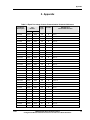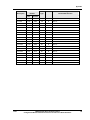
1
Modbus® RTU Serial Communications
User Manual
Configuration/Remote Calibration Interfaces for
HercuLine Smart Actuators
Doc. No.: 51-52-25-103
Revision: 2
Date:
Industrial Measurement and Control
11/03
Copyright, Notices, and Trademarks
Printed in U.S.A. – © Copyright 2003 by Honeywell Inc.
Revision 2 – November 2003
While this information is presented in good faith and believed to be
accurate, Honeywell disclaims the implied warranties of
merchantability and fitness for a particular purpose and makes no
express warranties except as may be stated in its written agreement
with and for its customer.
In no event is Honeywell liable to anyone for any indirect, special or
consequential damages. The information and specifications in this
document are subject to change without notice.
Modbus is a registered trademark of MODICON, Inc.
Windows is an addressed trademark of Microsoft Inc.
The omission of a name from this list is not to be interpreted that the
name is not a trademark.
Honeywell
Industrial Measurement and Control
1100 Virginia Drive
Fort Washington, PA 19034
ii
Modbus® RTU Serial Communications
Configuration/Remote Calibration Interfaces for HercuLine Smart Actuators
11/03
About This Document
Abstract
This document provides configuration information specific to Honeywell’s Herculine Smart Actuators
and should be used in conjunction with Modbus® RTU Serial Communications User Manual, document
number 51-52-25-66.
Contacts
World Wide Web
The following lists Honeywell’s World Wide Web sites that will be of interest to our customers.
Honeywell Organization
WWW Address (URL)
Corporate
http://www.honeywell.com
Industrial Measurement & Control
http://www.honeywell.com/imc
Telephone
Contact us by telephone at the numbers listed below.
Organization
United States and Canada
Honeywell
Phone Number
1-800-423-9883
1-888-423-9883
1-800-525-7439
Tech. Support
Q&A Faxback
(TACFAQS)
Service
References
Publication Title
Publication Number
10260S Herculine Smart Actuator Installation, Operation and
Maintenance Manual
62-86-25-08
11280S Herculine Smart Actuator Installation, Operation and
Maintenance Manual
61-86-25-09
HercuLine™ 2000 Series Actuator Installation, Operation and
Maintenance Manual
62-86-25-10
Modbus® RTU Serial Communications User Manual
51-52-25-66
Reference: Modicon Modbus Protocol Reference Guide
11/03
PI-MBUS-300
Modbus® RTU Serial Communications
Configuration/Remote Calibration Interfaces for HercuLine Smart Actuators
iii
iv
Modbus® RTU Serial Communications
Configuration/Remote Calibration Interfaces for HercuLine Smart Actuators
11/03
Contents
1.
MODBUS SERIAL COMUNICATIONS FOR HERCULINE ACTUATORS ...........1
1.1
Overview.........................................................................................................................................................1
2.
MODBUS RTU FUNCTION CODES.....................................................................3
2.1
General Information......................................................................................................................................3
2.2
Function Code 20 (14h) - Read Configuration Reference Data ................................................................5
2.3
Function Code 21 (15h) - Write Configuration Reference Data .............................................................11
3.
PARAMETERS AND REGISTER ADDRESSES ................................................17
3.1
Overview.......................................................................................................................................................17
3.2
Configuration Parameters ..........................................................................................................................17
4.
REMOTE CALIBRATION FUNCTION CODE.....................................................37
4.1
Function Code 57 (39h) - Remote Calibration Reference Data...............................................................37
5.
APPENDIX ..........................................................................................................47
11/03
Modbus® RTU Serial Communications
Configuration/Remote Calibration Interfaces for HercuLine Smart Actuators
v
Tables
Table 2-1 Integer Parameter Type _______________________________________________________ 3
Table 2-2 Floating-Point Parameter Type _________________________________________________ 3
Table 2-3 Enumeration Parameter Type __________________________________________________ 4
Table 2-4 String Parameter Type ________________________________________________________ 4
Table 2-5 Data Word Descriptions _______________________________________________________ 6
Table 2-6 Register Address Format for Function Code 20 ____________________________________ 6
Table 2-7 Data Word Descriptions _____________________________________________________ 12
Table 2-8 Register Address Format for Function Code 21 ___________________________________ 12
Table 3-1 Input Setup Group __________________________________________________________ 18
Table 3-2 Relay1 / Alarms Set-up Group _________________________________________________ 21
Table 3-3 Relay2 / Alarms Set-up Group _________________________________________________ 22
Table 3-4 Relay3 / Alarms Set-up Group _________________________________________________ 23
Table 3-5 Relay4 / Alarms Set-up Group _________________________________________________ 24
Table 3-6 Current Output Set-up Group _________________________________________________ 25
Table 3-7 Communications Set-up Group ________________________________________________ 26
Table 3-8 Digital Input Set-up Group ___________________________________________________ 28
Table 3-9 Display Set-up Group ________________________________________________________ 28
Table 3-10 Lockout Set-up Group ______________________________________________________ 29
Table 3-11 Read Status Set-up Group____________________________________________________ 29
Table 3-12 Drive Information Set-up Group ______________________________________________ 30
Table 3-13 Maintenance Set-up Group __________________________________________________ 33
Table 4-1 Data Word Descriptions _____________________________________________________ 38
Table 5-1 Equal Percentage Custom Characterization Parameter Addresses ______________________ 47
Table 5-2 Quick Opening Custom Characterization Parameter Addresses _______________________ 48
vi
Modbus® RTU Serial Communications
Configuration/Remote Calibration Interfaces for HercuLine Smart Actuators
11/03
Modbus Serial Comunications for Herculine Actuators
Overview
1. Modbus Serial Comunications for Herculine Actuators
1.1 Overview
Modbus Remote Terminal Unit (RTU) protocol provides a common data exchange format for connecting
field devices to both Honeywell and other master devices. This serial communication format allows field
devices to act as a slave device on a data link with other field devices that employ the Modbus RTU
protocol. The Honeywell Herculine Smart Actuator is capable of remote operation via an RS-485 serial
communications using Modbus RTU protocol.
This reference document describes the Modbus function codes and message formats used for remote
communications with the actuators. The physical and data link layers of the Modbus specificiation are
maintained. The Herculine actuators use only a subset of the Modbus RTU function codes. Messages
within the Modbus message frame use standard IEEE 32-bit floating point and 16-bit integer formats.
The actuators can be set up to communicate as a slave device on a RS-485 serial link that employs Modbus
RTU protocol. The actuator must be set up to accept input information from a remote source. A device
address must be specified, and a baud rate should be selected that is common to the master device on the
data link. Refer to the Operation and Maintenance Manual of the specific actuator model for the details on
setting up the actuator for remote operation.
Additional Information
For additional information on the Modbus RTU protocol, such as the physical and data link layers, refer to
the Modbus RTU Serial Communications User Manual (document number 51-52-25-66), or the Modicon
Modbus Protocol Reference Guide which is available from Modicon, Inc.
11/03
Modbus® RTU Serial Communications
Configuration/Remote Calibration Interfaces for HercuLine Smart Actuators
1
Modbus Serial Comunications for Herculine Actuators
Overview
2
Modbus® RTU Serial Communications
Configuration/Remote Calibration Interfaces for HercuLine Smart Actuators
11/03
Modbus RTU Function Codes
General Information
2. Modbus RTU Function Codes
2.1 General Information
The actuators use function codes 20 and 21 register addresses for read and write access of the configuration
and process-related data in the actuator. Standard IEEE-32-bit floating point and 16-bit interger formats
are used in transferring the message data. The register address structures for these message formats are
described in Table 2-1, Table 2-2, Table 2-3. The register addresses that are specific to the actuators are
explained in Section 3.2.
File Address Structure
Table 2-1 Integer Parameter Type
Register Address
(Hex)
Name
Access
Notes
0
Type = 1
Read
16-bit Unsigned Integer
1
Attribute
Read
1 = Read Only, 2 = Read/Write
2
Value (16 bit integer)
3
Not Used
Read
4
Low Range (16 bit integer)
Read
5
Not Used
Read
6
High Range (16 bit Integer)
Read
7
Not Used
Read
Description Text (ASCII string)
Read
8 to F
Read / Write
8 characters
Table 2-2 Floating-Point Parameter Type
Register Address
(Hex)
Access
Notes
0
Type = 2
Read
IEEE Floating Point
1
Attribute
Read
1 = Read Only, 2 = Read/Write
2
Value (float high word)
Read / Write
3
Value (float low word)
Read / Write
4
Low Range (float high word)
Read
5
Low Range (float low word)
Read
6
High Range (float high word)
Read
7
High Range (float low word)
Read
Description Text (ASCII string)
Read
8 to F
11/03
Name
8 characters
Modbus® RTU Serial Communications
Configuration/Remote Calibration Interfaces for HercuLine Smart Actuators
3
Modbus RTU Function Codes
General Information
File Address Structure
Table 2-3 Enumeration Parameter Type
Register Address
(Hex)
Name
Access
Notes
0
Type = 5
Read
16-bit Unsigned Integer
1
Attribute
Read
1 = Read Only, 2 = Read/Write
2
Value (16 bit integer)
3
Not Used
Read
4
Low Range (16 bit integer)
Read
5
Not Used
Read
6
High Range (16 bit Integer)
Read
7
Not Used
Read
Description Text (ASCII string)
Read
8 to F
Read / Write
8 characters
Note: Table 2-3 is only supported in the PDA interface.
Table 2-4 String Parameter Type
Register Address
(Hex)
Name
Access
Notes
0
Type = 4
Read
ASCII Text String
1
Attribute
Read
1 = Read Only, 2 = Read/Write
2
Value (16 bit integer)
Read / Write
Text String Pointer, 0 = attached
3
Not Used
Read
4
Pointer Low Limit (16 bit integer)
Read
5
Not Used
Read
6
Pointer High Limit (16 bit Integer)
Read
7
Not Used
Read
Text (ASCII string)
Read
8 to 8 + N
Minimum String Size; 6 chars
Maximum String Size; 6chars
N*2 characters
Note: Table 2-4 is only supported in the PDA interface.
4
Modbus® RTU Serial Communications
Configuration/Remote Calibration Interfaces for HercuLine Smart Actuators
11/03
Modbus RTU Function Codes
Function Code 20 (14h) - Read Configuration Reference Data
2.2 Function Code 20 (14h) - Read Configuration Reference Data
Description
Function code 20 (14 Hex) is used to read information stored in the configuration database of the actuator.
Each configuration parameter is uniquely addressed by a register address, and is detailed in Section 3. The
actuators configuration database is located in EEROM on the main CPU PWA.
Query and Response Formats
The Query and Response formats for Function code 20 (14 Hex) are shown below. Details for each data
block (or word) is described in Table 2-5.
Query Message Format
Slave
Address
Function
Code 14
Reference File
Number
Type
Type
Byte
Count
Reference
Type
Register
Address
Register
Count
File
Number
Register
Address
CRC
Data
Register
Count
CRC
Data
Response Message Format
11/03
Slave
Address
Function
Code 14
Byte
Count
Data
Byte
Count
Reference
Type
Data
Data
Reference
Data
Type
Data
Byte
Count
Reference
Type
Data
Data
Data
Data
CRC
Data
CRC
Data
Modbus® RTU Serial Communications
Configuration/Remote Calibration Interfaces for HercuLine Smart Actuators
Data
5
Modbus RTU Function Codes
Function Code 20 (14h) - Read Configuration Reference Data
Table 2-5 Data Word Descriptions
Data Word
Description
Slave Address
The address of the device on the data link for which the message is intended.
Function Code
Tells the device what kind of action to perform.
Equals the number of bytes transmitted in either the query or response
message and will be the minimum number required to transmit all queryed
data.
Byte Count
Data Byte Count
The number of data bytes of the sub response including the Reference Type
but not including itself. A sub response has four bytes of data and one byte
representing the reference type making the data byte count equal to five.
Reference Type
Definitions
The Reference Type definition is always 06.
See examples in Subsection 2.2.1 Read Configuration Data Examples.
File Number
The file number word represents the device parameter(s) that are being
accessed. The file number word is made up of two bytes.
Register Address
The register address word contains the register address from the file
structure tables on page 3. The register address is also made up of two
bytes.
Cyclical Redundancy Check provides error checking of the message and it
is the last field in the message.
CRC Data
Table 2-6 Register Address Format for Function Code 20
6
File Number
(Decimal)
File Number
(Hex)
Format
4096 to 4214
1000 to 1146
Analog formatted data
(2 registers – IEEE 32-bit floating point)
5120 to 5211
1400 to 145B
Integer formatted data
(1 register – 16-bit integer value + 16 bits of zero’s)
Modbus® RTU Serial Communications
Configuration/Remote Calibration Interfaces for HercuLine Smart Actuators
11/03
Modbus RTU Function Codes
Function Code 20 (14h) - Read Configuration Reference Data
2.2.1 Read Configuration Data Examples
Example #1
The following is an example of a query to read the Input Hi Range value using Function code 20.
Query Message
02 14 07 06 10 00 00 02 00 02 (CRC16)
Where:
02
14
07
06
10,00
00,02
00 02
(CRC16)
=
=
=
=
=
=
=
Address
Function Code 20 (14 hex)
Byte Count
Reference Type
File Number (Input Hi Range)
Register Address (Access Data Value)
Register Count (Floating Point Data)
This is the response to the above query.
Response Message
02 14 06 05 06 47 64 00 00 (CRC16)
Where:
02
14
06
05
06
47 64 00 00
(CRC16)
=
=
=
=
=
=
Address
Function Code 20 (14 Hex)
Byte Count
Sub Message Length
Reference Type
100.0 (Value of Input Hi Range)
continued next page
11/03
Modbus® RTU Serial Communications
Configuration/Remote Calibration Interfaces for HercuLine Smart Actuators
7
Modbus RTU Function Codes
Function Code 20 (14h) - Read Configuration Reference Data
Example #2
The following is another example of a query and response message using Function code 20.
(Read Input Hi and Input Lo range values)
Query Message
02 14 0E 06 10 00 00 02 00 02 06 10 02 00 02 00 02 (CRC16)
Where:
02
14
0E
06
10,00
00,02
00,02
06
10,02
00,02
00,02
(CRC16)
=
=
=
=
=
=
=
=
=
=
=
Address
Function Code 20 (14 Hex)
Byte Count
Reference Type
File Number (Input Hi Range)
Register Address (Access Data Value)
Register Count to read (Floating Point Data)
Reference Type
File Number (Input Lo Range)
Register Address (Access Data Value)
Register Count to read (Floating Point Data)
This is the response to the above query.
Response Message
02 14 0C 05 06 43 C8 00 00 05 06 44 60 00 00 (CRC16)
Where:
02
14
0C
05
06
43 C8 00 00
05
06
44 60 00 00
(CRC16)
=
=
=
=
=
=
=
=
=
Address
Function Code 20 (14 Hex)
Byte Count
Data Byte Count (Sub Message Length)
Reference Type
400.0 (Value of Input Hi Range)
Data Byte Count (Sub Message Length)
Reference Type
896.0 (Value of Input Lo Range)
continued next page
8
Modbus® RTU Serial Communications
Configuration/Remote Calibration Interfaces for HercuLine Smart Actuators
11/03
Modbus RTU Function Codes
Function Code 20 (14h) - Read Configuration Reference Data
Example #3
The following is an example of a query to read the input actuation value using Function code 20.
Query Message
02 14 07 06 14 00 00 02 00 02 (CRC16)
Where:
02
14
07
06
14,00
00,02
00 02
(CRC16)
=
=
=
=
=
=
=
Address
Function Code 20 (14 hex)
Byte Count
Reference Type
File Number (Input Hi Range)
Register Address (Access Data Value)
Register Count (Integer Data)
This is the response to the above query.
Response Message
02 14 06 05 06 00 02 00 00 (CRC16)
Where:
02
14
06
05
06
00 02
00 C8
(CRC16)
=
=
=
=
=
=
=
Address
Function Code 20 (14 Hex)
Byte Count
Sub Message Length
Reference Type
02 (Value of Input Actuation)
File Number
continued next page
11/03
Modbus® RTU Serial Communications
Configuration/Remote Calibration Interfaces for HercuLine Smart Actuators
9
Modbus RTU Function Codes
Function Code 20 (14h) - Read Configuration Reference Data
Example #4
The following is another example of a query and response message using Function code 20.
(Read Alarm 11 Type and Alarm 11 Event)
Query Message
02 14 0E 06 14 09 00 02 00 02 06 14 0A 00 02 00 02 (CRC16)
Where:
02
14
0E
06
14,09
00,02
00,02
06
14,0A
00,02
00,02
(CRC16)
=
=
=
=
=
=
=
=
=
=
=
Address
Function Code 20 (14 Hex)
Byte Count
Reference Type
File Number (Alarm 11 Type)
Register Address (Access Data Value)
Register Count to read (Integer Data)
Reference Type
File Number (Alarm 11 Event)
Register Address (Access Data Value)
Register Count to read (Integer Data)
This is the response to the above query.
Response Message
02 14 0C 05 06 00 03 00 00 05 06 00 01 00 00 (CRC16)
Where:
02
14
0C
05
06
00 03
00 D2
05
06
00 01
00 D3
(CRC16)
10
=
=
=
=
=
=
=
=
=
=
=
Address
Function Code 20 (14 Hex)
Byte Count
Data Byte Count (Sub Message Length)
Reference Type
03 (Value of Alarm 11 Type)
File Number
Data Byte Count (Sub Message Length)
Reference Type
01 (Value of Alarm 11 Event)
File Number
Modbus® RTU Serial Communications
Configuration/Remote Calibration Interfaces for HercuLine Smart Actuators
11/03
Modbus RTU Function Codes
Function Code 21 (15h) - Write Configuration Reference Data
2.3 Function Code 21 (15h) - Write Configuration Reference Data
Description
Function Code 21 (15 Hex) is used to allow writes of integer and floating point values to the configuration
database. Each configuration parameter is uniquely addressed by a register address, and is detailed in
Section 3. The configuration database is located in EEROM on the main CPU PWA.
Integer format is used to write to “Digital” configuration items. Floating Point format is used to write to
“Analog” configuration items.
Write Restrictions
Care should be taken not to exceed the 100,000 write limit of the EEROM.
Query and Response Formats
The Query and Response formats for Function code 21 (15 Hex) are shown below. Details for each data
block (or word) are described in Table 2-7.
Query Message Format
Slave
Address
Data
Function
Code 15
Data
Byte
Count
Data
Reference File
Type
Number
Data
Register
Address
File
Register
Count
CRC
Data
Number
CRC
Data
Response Message Format (echo back of query)
Slave
Address
Data
11/03
Function
Code 15
Data
Byte
Count
Data
Reference File
Type
Number
Data
File
Number
Register
Address
Register
Count
CRC
Data
CRC
Data
Modbus® RTU Serial Communications
Configuration/Remote Calibration Interfaces for HercuLine Smart Actuators
11
Modbus RTU Function Codes
Function Code 21 (15h) - Write Configuration Reference Data
Table 2-7 Data Word Descriptions
Data Word
Description
Slave Address
The address of the device on the data link for which the message is intended.
Function Code
Tells the device what kind of action to perform. In this case, write
configuration data.
Equals the number of bytes transmitted in either the query or response
message and will be the minimum number required to transmit all queryed
data.
Byte Count
The number of data bytes of the sub response including the Reference Type
but not including itself. A sub response has four bytes of data and one byte
representing the reference type making the data byte count equal to five.
Data Byte Count
The Reference Type definition is always 06.
See examples in Subsection 2.3.1 Write Configuration Examples.
Refernce Type
Definitions
The file number word represents the device parameter(s) that are being
accessed. The file number word is made up of two bytes.
File Number
Register Address
The register address word contains the register address from the file structure
tables on page 3. The register address is also made up of two bytes.
CRC Data
Cyclical Redundancy Check provides error checking of the message and it is
the last field in the message.
Table 2-8 Register Address Format for Function Code 21
File Number
File Number
(Dec)
(Hex)
4096 to 4214
1000 to 1146
Format
Analog formatted data
(2 registers – IEEE 32-bit floating point)
5120 to 5211
1400 to 145B
Integer formatted data
(1 register – 16 bit integer value)
12
Modbus® RTU Serial Communications
Configuration/Remote Calibration Interfaces for HercuLine Smart Actuators
11/03
Modbus RTU Function Codes
Function Code 21 (15h) - Write Configuration Reference Data
2.3.1 Write Configuration Data Examples
Example #1
The following is an example of a query to write the Deadband value using Function code 21 (15 Hex).
Query Message 02 15 0B 06 10 06 00 02 00 02 3F C0 00 00 (CRC16)
Where:
02
15
0B
06
10 06
00 02
00 02
3F C0 00 00
(CRC16)
=
=
=
=
=
=
=
=
Address
Function Code 21 (15 Hex)
Byte Count
Reference Type
File Number (Deadband)
Register Address (Access Data Value)
Register Count (Floating Point Data)
Data Value = (1.50)
This is the response to the above query.
Response Message (The response is an echo of the query)
02 15 0B 06 10 06 00 02 00 02 3F C0 00 00 (CRC16)
Example #2
The following is an example of a query to write the Deadband value and the Alarm SP1 value using
Function code 21 (15 Hex).
Query Message
02 15 0B 06 10 06 00 02 00 02 3F C0 00 00 06 10 36 00 02 00 02 3F C0 00 00 (CRC16)
Where:
02
15
0B
06
10 06
00 02
00 02
3F C0 00 00
06
10 36
00 02
00 02
3F C0 00 00
(CRC16)
=
=
=
=
=
=
=
=
=
=
=
=
=
Address
Function Code 21 (15 Hex)
Byte Count
Reference Type
File Number (Deadband)
Register Address (Access Data Value)
Register Count (Floating Point Data)
Data Value = (1.50)
Reference Type
File Number (Alarm SP1)
Register Address (Access Data Value)
Register Count (Floating Point Data)
Data Value = (1.50)
This is the response to the above query.
Response Message (The response is an echo of the query)
02 15 0B 06 10 06 00 02 00 02 3F C0 00 00 06 10 36 00 02 00 02 3F C0 00 00 (CRC16)
11/03
Modbus® RTU Serial Communications
Configuration/Remote Calibration Interfaces for HercuLine Smart Actuators
13
Modbus RTU Function Codes
Function Code 21 (15h) - Write Configuration Reference Data
Example #3
The following is an example of a query to write the Motor Direction value using Function code 21
(15 Hex).
Query Message 02 15 0B 06 14 02 00 02 00 01 00 01 (CRC16)
Where:
02
15
0B
06
14 02
00 02
00 01
00 01
(CRC16)
=
=
=
=
=
=
=
=
Address
Function Code 21 (15 Hex)
Byte Count
Reference Type
File Number (Motor Direction)
Register Address (Access Data Value)
Register Count (Integer Data )
Data Value = (1)
This is the response to the above query.
Response Message (The response is an echo of the query)
02 15 0B 06 14 02 00 02 00 02 00 01 (CRC16)
Example #4
The following is an example of a Query to write the Failsafe Type value and the Alarm 11 Event type
value using Function code 21 (15 Hex).
Query Message
02 15 0B 06 14 03 00 02 00 01 00 02 06 14 0A 00 02 00 01 00 00 (CRC16)
Where:
02
15
0B
06
14 03
00 02
00 01
00 02
06
14 0A
00 02
00 01
00 00
(CRC16)
=
=
=
=
=
=
=
=
=
=
=
=
=
Address
Function Code 21 (15 Hex)
Byte Count
Reference Type
File Number (Failsafe Type)
Register Address (Access Data Value)
Register Count
Data Value = (2)
Reference Type
File Number (Alarm 11 Event Type)
Register Address (Access Data Value)
Register Count
Data Value = (0)
This is the response to the above query.
Response Message (The response is an echo of the query)
02 15 0B 06 14 03 00 02 00 01 00 02 06 14 0A 00 02 00 01 00 00 (CRC16)
14
Modbus® RTU Serial Communications
Configuration/Remote Calibration Interfaces for HercuLine Smart Actuators
11/03
Modbus RTU Function Codes
Function Code 21 (15h) - Write Configuration Reference Data
11/03
Modbus® RTU Serial Communications
Configuration/Remote Calibration Interfaces for HercuLine Smart Actuators
15
Parameters and Register Addresses
Overview
3. Parameters and Register Addresses
3.1 Overview
Introduction
This section provides maps of the configuration parameters in the Herculine actuator. Using Function
codes 20 and 21 you can read and write configuration values to the actuator. The configuration parameters
are arranged according to the set up groups in which they appear when using the local display and keypad
interface.
Each parameter is listed with its register address, data format type (32-bit floating point or 16-bit integer)
and available selections.
General Information
Analog / Digital Parameters
Whenever configuration parameter values are changed via communications, a write cycle occurs after the
response is returned acknowledging receipt of the message.
3.2 Configuration Parameters
Overview
Listed on the following pages are the parameters in the various set-up groups within the actuator. The setup groups and their table numbers are listed below. Most of the parameters are configurable through the
hosts. Some parameters are read only and are indicated as such and therefore cannot be changed.
Set-up Group
See Table Number
Input................................................................................................................ Table 3-1
Relay1 ............................................................................................................. Table 3-2
Relay2 ............................................................................................................. Table 3-3
Relay3 ............................................................................................................. Table 3-4
Relay4 ............................................................................................................. Table 3-5
Current Output ................................................................................................ Table 3-6
Communications ............................................................................................. Table 3-7
Digital Input.................................................................................................... Table 3-8
Display............................................................................................................ Table 3-9
Lockout ........................................................................................................... Table 3-10
Status............................................................................................................... Table 3-11
Drive Information ........................................................................................... Table 3-12
Maintenance.................................................................................................... Table 3-13
Reading or Writing
Do a read or write, depending on your requirements, using the format code listed in the tables. The range
or selection available for each range is listed in the tables.
11/03
Modbus® RTU Serial Communications
Configuration/Remote Calibration Interfaces for HercuLine Smart Actuators
17
Parameters and Register Addresses
Configuration Parameters
3.2.1 Input
Table 3-1lists all the register addresses with ranges or selections for parameters in the Input set-up group.
Table 3-1 Input Setup Group
Parameter
Description
Input Type
File
Number
Hex
Decimal
1400
5120
Data
Type
Access
INT
R/W
Note: If input type
from model
selection guide is:
0/4-20mA, 0/15Vdc, 0-10Vdc
Data Range or
Enumerated Selection
0 = 4-20 mA
1 = 0-20 mA
2 = 1-5 Vdc
3 = 0-5 Vdc
4 = 0-10 Vdc
5 = R_SP
Note: Changing the Input Type will
result in the loss of field calibration
values for the old input type; and will
restore the factory calibration values
for the new selected input type.
Input Type
1400
5120
INT
R
6 = Series 90 (Read Only)
(SA2000 Models
Only)
Note: If input type
from model
selection guide is:
Series 90 control
18
Note: Input Type can not be changed.
Input Hi Range
Value
1000
4096
FP
R/W
10.0 to 100.0 %
Input Lo Range
Value
1002
4098
FP
R/W
0.0 to 90.0 %
Input Filter Type
1401
5121
INT
R/W
0 = None
1 = Spike Only
2 = Spike + Low Pass
3 = Low Pass Only
Low Pass Value
1004
4100
FP
R/W
0.0 to 50.0 Seconds
Direction
1402
5122
INT
R/W
0 = CCW
1 = CW
Deadband
1006
4102
FP
R/W
0.2 to 5.0 %
Failsafe Type
1403
5123
INT
R/W
0 = Last
1 = Up
2 = Down
3 = User Defined
Failsafe User
Defined Value
1008
4104
FP
R/W
0.0 to 100.0 %
Characterization
Type
1404
5124
INT
R/W
0 = Linear
1 = Square Root
2 = Custom
Modbus® RTU Serial Communications
Configuration/Remote Calibration Interfaces for HercuLine Smart Actuators
11/03
Parameters and Register Addresses
Configuration Parameters
Table 3-1 Input Setup Group, continued
Parameter
Description
File
Number
Data
Type
Access
Data Range or
Enumerated Selection
Hex
Decimal
Custom
Characterization
Type
145A
5210
INT
R/W
0 = Equal Percentage
1 = Quick Openning
2 = User Configurable
X0 Value
100A
4106
FP
R/W
0.0 to 100.0 %
X1 Value
100C
4108
FP
R/W
0.0 to 100.0 %
X2 Value
100E
4110
FP
R/W
0.0 to 100.0 %
X3 Value
1010
4112
FP
R/W
0.0 to 100.0 %
X4 Value
1012
4114
FP
R/W
0.0 to 100.0 %
X5 Value
1014
4116
FP
R/W
0.0 to 100.0 %
X6 Value
1016
4118
FP
R/W
0.0 to 100.0 %
X7 Value
1018
4120
FP
R/W
0.0 to 100.0 %
X8 Value
101A
4122
FP
R/W
0.0 to 100.0 %
X9 Value
101C
4124
FP
R/W
0.0 to 100.0 %
X10 Value
101E
4126
FP
R/W
0.0 to 100.0 %
X11 Value
1078
4216
FP
R/W
0.0 to 100.0 %
X12 Value
107A
4218
FP
R/W
0.0 to 100.0 %
X13 Value
107C
4220
FP
R/W
0.0 to 100.0 %
X14 Value
107E
4222
FP
R/W
0.0 to 100.0 %
X15 Value
1080
4224
FP
R/W
0.0 to 100.0 %
X16 Value
1082
4226
FP
R/W
0.0 to 100.0 %
X17 Value
1084
4228
FP
R/W
0.0 to 100.0 %
X18 Value
1086
4230
FP
R/W
0.0 to 100.0 %
X19 Value
1088
4232
FP
R/W
0.0 to 100.0 %
X20 Value
108A
4234
FP
R/W
0.0 to 100.0 %
Y0 Value
1020
4128
FP
R/W
0.0 to 100.0 %
Y1 Value
1022
4130
FP
R/W
0.0 to 100.0 %
Y2 Value
1024
4132
FP
R/W
0.0 to 100.0 %
Y3 Value
1026
4134
FP
R/W
0.0 to 100.0 %
Y4 Value
1028
4136
FP
R/W
0.0 to 100.0 %
Y5 Value
102A
4138
FP
R/W
0.0 to 100.0 %
Continued on next page ⇒
11/03
Modbus® RTU Serial Communications
Configuration/Remote Calibration Interfaces for HercuLine Smart Actuators
19
Parameters and Register Addresses
Configuration Parameters
Table 3-1 Input Setup Group , continued
Parameter
Description
File
Number
Data
Type
Access
Data Range or
Enumerated Selection
Hex
Decimal
Y6 Value
102C
4140
FP
R/W
0.0 to 100.0 %
Y7 Value
102E
4142
FP
R/W
0.0 to 100.0 %
Y8 Value
1030
4144
FP
R/W
0.0 to 100.0 %
Y9 Value
1032
4146
FP
R/W
0.0 to 100.0 %
Y10 Value
1034
4148
FP
R/W
0.0 to 100.0 %
Y11 Value
108C
4236
FP
R/W
0.0 to 100.0 %
Y12 Value
108E
4238
FP
R/W
0.0 to 100.0 %
Y13 Value
1090
4240
FP
R/W
0.0 to 100.0 %
Y14 Value
1092
4242
FP
R/W
0.0 to 100.0 %
Y15 Value
1094
4244
FP
R/W
0.0 to 100.0 %
Y16 Value
1096
4246
FP
R/W
0.0 to 100.0 %
Y17 Value
1098
4248
FP
R/W
0.0 to 100.0 %
Y18 Value
109A
4250
FP
R/W
0.0 to 100.0 %
Y19 Value
109C
4252
FP
R/W
0.0 to 100.0 %
Y20 Value
109E
4254
FP
R/W
0.0 to 100.0 %
Note: The X and Y value addresses shown above are for the User Configurable Custom Characterization
selection.
Address tables for the Equal Percentage and the Quick Openning can be found in the appendix at the rear
of
this document.
20
Modbus® RTU Serial Communications
Configuration/Remote Calibration Interfaces for HercuLine Smart Actuators
11/03
Parameters and Register Addresses
Configuration Parameters
3.2.2 Relay1 / Alarms
Table 3-2 lists all the register addresses and ranges or selections for function parameters in the Relay1
set-up group.
Table 3-2 Relay1 / Alarms Set-up Group
Parameter
Description
Relay1 SP1 Type
Hex
Decimal
140A
5130
Data
Type
Access
INT
R/W
Data Range or
Enumerated Selection
0 = None
1 = Input Range
2 = Position Range
3 = Deviation
4 = Upper Travel Limit
5 = LowerTravel Limit
6 = Temperature Hi
7 = Temperature Lo
8 = Starts
9 = Stalled Motor
10 = Manual Mode
11 = Power Up Test Fail
12 = Input Signal Fail
13 = Position Sensor Fail
14 = Digital Input Activated
= Total Degrees Traveled
Relay1 SP1 Value
1036
4150
FP
R/W
Within the range for the selected
relay type.
Relay1 SP1 Event
140B
5131
INT
R/W
0 = Low Alarm
1 = High Alarm
Relay1 SP1 Scale
140C
5132
INT
R/W
0=x1
1 = x 10K
Relay1 SP2 Type
140D
5133
INT
R/W
0 = None
1 = Input Range
2 = Position Range
3 = Deviation
4 = Upper Travel Limit
5 = LowerTravel Limit
6 = Temperature Hi
7 = Temperature Lo
8 = Starts
9 = Stalled Motor
10 = Manual Mode
11 = Power Up Test Fail
12 = Input Signal Fail
13 = Position Sensor Fail
14 = Digital Input Activated
= Total Degrees Traveled
Relay1 SP2 Value
11/03
File
Number
1038
4152
FP
R/W
15
15
Within the range of the selected
relay type
Modbus® RTU Serial Communications
Configuration/Remote Calibration Interfaces for HercuLine Smart Actuators
21
Parameters and Register Addresses
Configuration Parameters
Relay1 SP2 Event
140E
5134
INT
R/W
0 = Low Alarm
1 = High Alarm
Relay1 SP2 Scale
140F
5135
INT
R/W
0=x1
1 = x 10K
Relay1 Hysteresis
103A
4154
FP
R/W
0.0 to 100%
3.2.3 Relay2 / Alarms
Table 3-3 lists all the register addresses and ranges or selections for function parameters in the Relay2
set-up group.
Table 3-3 Relay2 / Alarms Set-up Group
Parameter
Description
Relay2 SP1 Type
22
File
Number
Hex
Decimal
1410
5136
Data
Type
Access
INT
R/W
Data Range or
Enumerated Selection
0 = None
1 = Input Range
2 = Position Range
3 = Deviation
4 = Upper Travel Limit
5 = LowerTravel Limit
6 = Temperature Hi
7 = Temperature Lo
8 = Starts
9 = Stalled Motor
10 = Manual Mode
11 = Power Up Test Fail
12 = Input Signal Fail
13 = Position Sensor Fail
14 = Digital Input Activated
= Total Degrees Traveled
15
Relay2 SP1 Value
103C
4156
FP
R/W
Within the range for the selected
relay type.
Relay2 SP1 Event
1411
5137
INT
R/W
0 = Low Alarm
1 = High Alarm
Relay2 SP1 Scale
1412
5138
INT
R/W
0=x1
1 = x 10K
Relay2 SP2 Type
1413
5139
INT
R/W
0 = None
1 = Input Range
2 = Position Range
3 = Deviation
4 = Upper Travel Limit
5 = LowerTravel Limit
6 = Temperature Hi
7 = Temperature Lo
8 = Starts
9 = Stalled Motor
10 = Manual Mode
11 = Power Up Test Fail
12 = Input Signal Fail
13 = Position Sensor Fail
14 = Digital Input Activated
= Total Degrees Traveled
Modbus® RTU Serial Communications
Configuration/Remote Calibration Interfaces for HercuLine Smart Actuators
15
11/03
Parameters and Register Addresses
Configuration Parameters
Relay2 SP2 Value
103E
4158
FP
R/W
Within the range of the selected
relay type
Relay2 SP2 Event
1414
5140
INT
R/W
0 = Low Alarm
1 = High Alarm
Relay2 SP2 Scale
1415
5141
INT
R/W
0=x1
1 = x 10K
Relay2 Hysteresis
1040
4160
FP
R/W
0.0 to 100%
3.2.4 Relay3 / Alarms
Table 3-4 lists all the register addresses and ranges or selections for function parameters in the Relay3
set-up group.
Table 3-4 Relay3 / Alarms Set-up Group
Parameter
Description
Relay3 SP1 Type
11/03
File
Number
Hex
Decimal
1416
5142
Data
Type
Access
INT
R/W
Data Range or
Enumerated Selection
0 = None
1 = Input Range
2 = Position Range
3 = Deviation
4 = Upper Travel Limit
5 = LowerTravel Limit
6 = Temperature Hi
7 = Temperature Lo
8 = Starts
9 = Stalled Motor
10 = Manual Mode
11 = Power Up Test Fail
12 = Input Signal Fail
13 = Position Sensor Fail
14 = Digital Input Activated
= Total Degrees Traveled
Relay3 SP1 Value
1042
4162
FP
R/W
Within the range for the selected
relay type.
Relay3 SP1 Event
1417
5143
INT
R/W
0 = Low Alarm
1 = High Alarm
Relay3 SP1 Scale
1418
5144
INT
R/W
0=x1
1 = x 10K
Modbus® RTU Serial Communications
Configuration/Remote Calibration Interfaces for HercuLine Smart Actuators
15
23
Parameters and Register Addresses
Configuration Parameters
Relay3 SP2 Type
1419
5145
INT
R/W
0 = None
1 = Input Range
2 = Position Range
3 = Deviation
4 = Upper Travel Limit
5 = LowerTravel Limit
6 = Temperature Hi
7 = Temperature Lo
8 = Starts
9 = Stalled Motor
10 = Manual Mode
11 = Power Up Test Fail
12 = Input Signal Fail
13 = Position Sensor Fail
14 = Digital Input Activated
= Total Degrees Traveled
Relay3 SP2 Value
1044
4164
FP
R/W
Within the range of the selected
relay type
Relay3 SP2 Event
141A
5146
INT
R/W
0 = Low Alarm
1 = High Alarm
Relay3 SP2 Scale
141B
5147
INT
R/W
0=x1
1 = x 10K
Relay3 Hysteresis
1046
4166
FP
R/W
0.0 to 100%
15
3.2.5 Relay4 / Alarms
Table 3-5 lists all the register addresses and ranges or selections for function parameters in the Relay4
set-up group.
Table 3-5 Relay4 / Alarms Set-up Group
Parameter
Description
Relay4 SP1 Type
24
File
Number
Hex
Decimal
141C
5148
Data
Type
Access
INT
R/W
Data Range or
Enumerated Selection
0 = None
1 = Input Range
2 = Position Range
3 = Deviation
4 = Upper Travel Limit
5 = LowerTravel Limit
6 = Temperature Hi
7 = Temperature Lo
8 = Starts
9 = Stalled Motor
10 = Manual Mode
11 = Power Up Test Fail
12 = Input Signal Fail
13 = Position Sensor Fail
14 = Digital Input Activated
= Total Degrees Traveled
15
Relay4 SP1 Value
1048
4168
FP
R/W
Within the range for the selected
relay type.
Relay4 SP1 Event
141D
5149
INT
R/W
0 = Low Alarm
1 = High Alarm
Modbus® RTU Serial Communications
Configuration/Remote Calibration Interfaces for HercuLine Smart Actuators
11/03
Parameters and Register Addresses
Configuration Parameters
Relay4 SP1 Scale
141E
5150
INT
R/W
0=x1
1 = x 10K
Relay4 SP2 Type
141F
5151
INT
R/W
0 = None
1 = Input Range
2 = Position Range
3 = Deviation
4 = Upper Travel Limit
5 = LowerTravel Limit
6 = Temperature Hi
7 = Temperature Lo
8 = Starts
9 = Stalled Motor
10 = Manual Mode
11 = Power Up Test Fail
12 = Input Signal Fail
13 = Position Sensor Fail
14 = Digital Input Activated
= Total Degrees Traveled
Relay4 SP2 Value
104A
4170
FP
R/W
Within the range of the selected
relay type
Relay4 SP2 Event
1420
5152
INT
R/W
0 = Low Alarm
1 = High Alarm
Relay4 SP2 Scale
1421
5153
INT
R/W
0=x1
1 = x 10K
Relay4 Hysteresis
104C
4172
FP
R/W
0.0 to 100%
15
3.2.6 Current Output
Table 3-6 lists all the register addresses and ranges or selections for function parameters in the Current
Output set-up group.
Table 3-6 Current Output Set-up Group
Parameter
Description
11/03
File
Number
Data
Type
Access
Data Range or
Enumerated Selection
Hex
Decimal
Current Output Type
Note: If output type
from model selection
guide is:
0/4-20mA, 0/1-5Vdc
1406
5126
INT
R/W
Current Output Type
Note: If output type
from model selection
guide is:
Slidewire Emulation
1406
5126
INT
R
4 = Slidewire Emulation
Current Output Type
Note: If output type
from model selection
guide is: None
1406
5126
INT
R
5 = None (Read Only)
0 = 4-20mA
1 = 0-20mA
2 = 1-5vdc
3 = 0-5vdc
Modbus® RTU Serial Communications
Configuration/Remote Calibration Interfaces for HercuLine Smart Actuators
25
Parameters and Register Addresses
Configuration Parameters
3.2.7 Communications
Table 3-7 lists all the register addresses and ranges or selections for function parameters in the
Communications set-up group.
Table 3-7 Communications Set-up Group
Parameter
Description
26
File
Number
Data
Type
Access
Data Range or
Enumerated Selection
Hex
Decimal
Comm Address
104E
4174
FP
R/W
1 to 99
Baud Rate
1451
5201
INT
R/W
0 = 2400
1 = 4800
2 = 9600
3 = 19200
Transmit Delay
1408
5128
INT
R/W
0 = None
1 = 10mS
2 = 20mS
3 = 30mS
4 = 40mS
5 = 50mS
Modbus® RTU Serial Communications
Configuration/Remote Calibration Interfaces for HercuLine Smart Actuators
11/03
Parameters and Register Addresses
Configuration Parameters
Floating Point Byte
Order
11/03
1409
5129
INT
R/W
0 = FP_B
1 = FP_BB
2 = FP_L
3 = FP_LB
Modbus® RTU Serial Communications
Configuration/Remote Calibration Interfaces for HercuLine Smart Actuators
27
Parameters and Register Addresses
Configuration Parameters
3.2.8 Digital Input
Table 3-8 lists all the register addresses and ranges or selections for function parameters in the Digital
Input set-up group.
Table 3-8 Digital Input Set-up Group
Parameter
Description
File
Number
Data
Type
Access
Hex
Decimal
Digital Input Type
1422
5154
INT
R/W
User Defined
Position
1050
4176
FP
R/W
Data Range or
Enumerated Selection
0 = None
1 = Up
2 = Down
3 = User
0.0 to 100.0 %
3.2.9 Display
Table 3-9 lists all the register addresses and ranges or selections for function parameters in the Display
set-up group.
Table 3-9 Display Set-up Group
Parameter
Description
28
File
Number
Data
Type
Access
Data Range or
Enumerated Selection
Hex
Decimal
Decimal Point
Location
1423
5155
INT
R/W
0 = XXXX
1 = XXX.X
Engineering Units
1424
5156
INT
R/W
0 = Percent
1 = Degrees
Display Units
1425
5157
INT
R/W
0 = SI
1 = English
Modbus® RTU Serial Communications
Configuration/Remote Calibration Interfaces for HercuLine Smart Actuators
11/03
Parameters and Register Addresses
Configuration Parameters
3.2.10 Lockout
Table 3-10 lists all the register addresses and ranges or selections for function parameters the Lockout
set-up group.
Table 3-10 Lockout Set-up Group
Parameter
Description
File
Number
Data
Type
Access
Data Range or
Enumerated Selection
Hex
Decimal
Keyboard Lockout
1426
5158
INT
R/W
0 = None
1 = Calibration
2 = Configuration
3 = Full
Auto/Man Lockout
144C
5196
INT
R/W
0 = Locked
1 = Unlocked
3.2.11 Read Status
Table 3-11 lists all the register addresses and ranges or selections for function parameters the Read Status
set-up group.
Table 3-11 Read Status Set-up Group
Parameter
Description
Software Status
File
Number
Hex
Decimal
1427
5159
Data
Type
Access
INT
R
Data Range or
Enumerated Selection
Bit Packed
Bit0 = Failsafe
Bit1 = RAM Test
Bit2 = Config. Checksum
Bit3 = Working Calibration
Checksum
Bit4 = SEE Test
0 = OK
1 = Failure
Hardware Status
144D
5197
INT
R
Bit Packed
Bit0 = Relay Board1
Bit1 = Relay Board2
Bit2 = Display / Keypad
0 = Not Installed
1 = Installed
11/03
Modbus® RTU Serial Communications
Configuration/Remote Calibration Interfaces for HercuLine Smart Actuators
29
Parameters and Register Addresses
Configuration Parameters
3.2.12 Drive Information
Table 3-12 lists all the register addresses and ranges or selections for function parameters in the Drive
Information set-up group.
Table 3-12 Drive Information Set-up Group
Parameter
Description
File
Number
Data
Type
Access
Hex
Decimal
Firmware Version #
142E
5166
INT
R
Motor Speed
142F
5167
INT
R
(10260S Model)
Motor Speed
142F
5167
INT
R
142F
5167
INT
R
142F
5167
INT
R
1430
5168
INT
R
1430
5168
INT
R
(For 10260S &
SA2000 Models)
Power
(11280S Models)
30
50HZ
0 = 10 Second
1 = 30 Second
2 = 60 Second
60 HZ
50 HZ
60HZ
50HZ
0 = 3.6 Second / 4.5 Seconds
1 = 7.2 Second / 9 Seconds
2 = 15 Second / 18 Seconds
3 = 30 Second / 36 Seconds
4 = 45 Second 54 Seconds
SA2000 90° Models
Power
60HZ
0 = 06 Second / 7.5 Seconds
1 = 12 Second / 15 Seconds
2 = 25 Second / 30 Seconds
3 = 50 Second / 60 Seconds
4 = 75 Second / 90 Seconds
SA2000 150° Models
Motor Speed
ASCII character ‘0-9’ only
0 = 10 Seconds / 12 Seconds
1 = 20 Seconds / 24 Seconds
2 = 40 Seconds / 48 Seconds
3 = 60 Seconds / 72 Seconds
4 = 20 Seconds / 24 Seconds
5 = 40 Seconds / 48 Seconds
6 = 60 Seconds / 72 Seconds
7 = 40 Seconds / 48 Seconds
8 = 60 Seconds / 72 Seconds
(11280S Models)
Motor Speed
Data Range or
Enumerated Selection
0 = 120 Volts @ 60 Hz
1 = 120 Volts @ 50 Hz
2 = 220 Volts @ 60 Hz
3 = 220 Volts @ 50 Hz
0 = 120 Volts @ 60 Hz Single
1 = 240 Volts @ 60 Hz Single
2 = 240 Volts @ 60 Hz Three
3 = 480 Volts @ 60 Hz Three
4 = 575 Volts @ 60 Hz Three
Modbus® RTU Serial Communications
Configuration/Remote Calibration Interfaces for HercuLine Smart Actuators
11/03
Parameters and Register Addresses
Configuration Parameters
Table 3-12 Drive Information Set-up Group, continued
Parameter
Description
File
Number
Data
Type
Access
Hex
Decimal
Rotation
(SA2000 Models)
144E
5198
INT
R
0 = 90 Degrees
1 = 150 Degrees
Rotation
(10260S / 11280S
Models)
144E
5198
INT
R
0 = 90 Degrees
Torque
144F
5199
INT
R
0 = 50 lb-in
1 = 100 lb-in
2 = 200 lb-in
3 = 400 lb-in
4 = 400 lb-in
/
/
/
/
/
6.0 N-M
11.5 N-M
22.5 N-M
45.0 N-M
45.0 N-M
144F
5199
INT
R
0 = 10 lb-ft
1 = 20 lb-ft
2 = 40 lb-ft
3 = 60 lb-ft
4 = 40 lb-ft
5 = 80 lb-ft
6 = 150 lb-ft
7 = 200 lb-ft
8 = 300 lb-ft
/
/
/
/
/
/
/
/
/
15 N-M
27 N-M
55 N-M
80 N-M
55 N-M
110 N-M
200 N-M
270 N-M
400 N-M
144F
5199
INT
R
0 = 425 lb-ft
1 = 850 lb-ft
2 = 1500 lb-ft
3 = 2500 lb-ft
4 = 4000 lb-ft
5 = 5500 lb-ft
Tag1
1431
5169
INT
R/W
ASCII character ‘0-9’ or ‘A-Z’
or ‘a-z’ or a ‘space’
Tag2
1432
5170
INT
R/W
ASCII character ‘0-9’ or ‘A-Z’
or ‘a-z’ or a ‘space’
Tag3
1433
5171
INT
R/W
ASCII character ‘0-9’ or ‘A-Z’
or ‘a-z’ or a ‘space’
Tag4
1434
5172
INT
R/W
ASCII character ‘0-9’ or ‘A-Z’
or ‘a-z’ or a ‘space’
Tag5
1435
5173
INT
R/W
ASCII character ‘0-9’ or ‘A-Z’
or ‘a-z’ or a ‘space’
Tag6
1436
5174
INT
R/W
ASCII character ‘0-9’ or ‘A-Z’
or ‘a-z’ or a ‘space’
(SA2000 Models)
Torque
(10260S Models)
Torque
(11280S Models)
11/03
Data Range or
Enumerated Selection
/
/
/
/
/
/
575 N-M
1150 N-M
2025 N-M
3400 N-M
5425 N-M
7450 N-M
Modbus® RTU Serial Communications
Configuration/Remote Calibration Interfaces for HercuLine Smart Actuators
31
Parameters and Register Addresses
Configuration Parameters
Table 3-12 Drive Information Set-up Group, continued
Parameter
Description
32
File
Number
Data
Type
Access
Data Range or
Enumerated Selection
Hex
Decimal
Last Cal Date Digit 1
1443
5187
INT
R/W
ASCII character ‘0 – 9’ only
Last Cal Date Digit 2
1444
5188
INT
R/W
ASCII character ‘0 – 9’ only
Last Cal Date Digit 3
1445
5189
INT
R/W
ASCII character ‘0 – 9’ only
Last Cal Date Digit 4
1446
5190
INT
R/W
ASCII character ‘0 – 9’ only
Last Cal Date Digit 5
1447
5191
INT
R/W
ASCII character ‘0 – 9’ only
Last Cal Date Digit 6
1448
5192
INT
R/W
ASCII character ‘0 – 9’ only
Repair Type
1449
5193
INT
R
0 = None
1 = Communications Board
2 = NCS
3 = CPU
4 = Motor
5 = Power Board
6 = Switch
7 = Relay
8 = Gears
9 = Water Damage
10 = Heat Damage
11 = Over Voltage Damage
12 = Model Reconfigured
13 = Warranty Repair
Modbus® RTU Serial Communications
Configuration/Remote Calibration Interfaces for HercuLine Smart Actuators
11/03
Parameters and Register Addresses
Configuration Parameters
3.2.13 Maintenance
Table 3-13 lists all the register addresses and ranges or selections for function parameters in the
Maintenance set-up group.
Table 3-13 Maintenance Set-up Group
Parameter
Description
File
Number
Data
Type
Access
Data Range or
Enumerated Selection
Hex
Decimal
Temperature Actual
1052
4178
FP
R
Temperature Max
1054
4180
FP
R
Temperature Min
1056
4182
FP
R
Accumulated Stall
Time
144A
5194
INT
R
0 to 6000 minutes
Accumulated Starts
1058
4184
FP
R
0 to 99,990,000
Relay1 Cycle Count
105A
4186
FP
R
0 to 99,990,000
Relay2 Cycle Count
105C
4188
FP
R
0 to 99,990,000
Relay3 Cycle Count
105E
4190
FP
R
0 to 99,990,000
Relay4 Cycle Count
1060
4192
FP
R
0 to 99,990,000
Region0 Count
1062
4194
FP
R
0 to 99,990,000
Region1 Count
1064
4196
FP
R
0 to 99,990,000
Region2 Count
1066
4198
FP
R
0 to 99,990,000
Region3 Count
1068
4200
FP
R
0 to 99,990,000
Region4 Count
106A
4202
FP
R
0 to 99,990,000
Region5 Count
106C
4204
FP
R
0 to 99,990,000
Region6 Count
106E
4206
FP
R
0 to 99,990,000
Region7 Count
1070
4208
FP
R
0 to 99,990,000
Region8 Count
1072
4210
FP
R
0 to 99,990,000
Region9 Count
1074
4212
FP
R
0 to 99,990,000
Total Degrees
1076
4214
FP
R
0 to 99,990,000
Save Maintenance
Data
1452
5202
INT
R/W
0 = Disabled
1 = Enabled
Continued on next page ⇒
11/03
Modbus® RTU Serial Communications
Configuration/Remote Calibration Interfaces for HercuLine Smart Actuators
33
Parameters and Register Addresses
Configuration Parameters
Table 3-13 Maintenance Set-up Group, continued
Parameter
Description
File
Number
Data
Type
Access
Data Range or
Enumerated Selection
Hex
Decimal
Reset Type
144B
5195
INT
R/W
0 = None
1 = Accumulated Stall Time
2 = Cycle Count
3 = Region 0 Count
4 = Region 1 Count
5 = Region 2 Count
6 = Region 3 Count
7 = Region 4 Count
8 = Region 5 Count
9 = Region 6 Count
10 = Region 7 Count
11 = Region 8 Count
12 = Region 9 Count
13 = Temperature
14 = Total Degrees
15 = Relay 1 Count
16 = Relay 2 Count
17 = Relay 3 Count
18 = Relay 4 Count
19 = All
20 = System
Factory Cal Restore
1405
5125
INT
R/W
0 = None
1 = Input
2 = Motor
3 = Current Output
4 = All
5 = NCS
Factory Config Restore
1450
5200
INT
R/W
0 = Disabled
1 = Enable Restore Default
Factory Cfg.
System Restart
145B
5211
INT
R/W
0 = Disabled
1 = Enable System Restart
Note*
*Note: This function can only be accessed when the Reset Type function has been set to System (#20).
34
Modbus® RTU Serial Communications
Configuration/Remote Calibration Interfaces for HercuLine Smart Actuators
11/03
Parameters and Register Addresses
Configuration Parameters
11/03
Modbus® RTU Serial Communications
Configuration/Remote Calibration Interfaces for HercuLine Smart Actuators
35
Remote Calibration Function Code
Function Code 57 (39h) - Remote Calibration Reference Data
4. Remote Calibration Function Code
4.1 Function Code 57 (39h) - Remote Calibration Reference Data
Description
Function code 57 (39 Hex) is used in the Herculine Actuator to perform field calibration of the input,
output and motor circuits remotely through Modbus communications.
Each calibration type is uniquely addressed by a code that is representative of the code created when the
calibration is performed using the local display/keypad on the actuator. The calibration routines are state
driven (using group and function address), meaning there’s a sequence that must be followed to
successfully complete the calibration. If the state requests (function addresses) being transmitted to the
unit become out of sequence, the unit will respond with an error message. If the same state request
(function address) is sent more than once, the unit will respond with an error message. Any request to the
unit that results in an error response is interpreted as illegal request.
Query and Response Formats
The Query and Response formats for Function code 57 (39 Hex) are shown below. Details for each data
block (or word) are described in Table 4-1.
Query Message Format
Slave
Address
Function
Code 39
Byte
Count
Data
Referenc
Lo Type
(2)
CRC
Data
CRC
Data
Command
Type
Group
Address
Function
Address
Data
Hi (2)
Response Message Format (echo back of query)
11/03
Slave
Address
Function
Code 39
CRC
Data
CRC
Data
Byte
Count
Command Group
Function Data Hi
Address
Type
Address
Data Lo
Modbus® RTU Serial Communications
Configuration/Remote Calibration Interfaces for HercuLine Smart Actuators
37
Remote Calibration Function Code
Function Code 57 (39h) - Remote Calibration Reference Data
Table 4-1 Data Word Descriptions
Data Word
Description
Slave Address
The address of the device on the data link for which the message is intended.
(1 byte)
Function Code
Tells the device what kind of action to perform.
Byte Count
Command Type
Setup Group Address
Equals the number of bytes transmitted in either the query or the response
message and will be the minimum number required to transmit all data.
(1 byte)
This byte should always be 1.
(1 byte)
This is the code that represents the Group I.D. # that is generated when the
group is accessed from the keypad/display using the setup key.
The Group I.D. Codes are as follows:
9 = Calibrate Input
10 = Calibrate Motor
11 = Calibrate Output
16 = NCS Calibrator
Group Function
Address
(1 byte)
(1 byte)
This is the code that represents the Function I.D. # that is generated when
the functions of the selected group are accessed from the keypad/display
using the function key. This will also be used to indicate increment and
decrement functionality. The Function I.D. codes (States) are as follows:
0 = Select the Calibration Group
1 = Invoke the Selected Calibration Group
2 = Enable the Calibration Function
3 = Activate the Calibration Lo Function
4 = Activate the Calibration Hi Function *
5 = Terminate the Calibration
**
6 = Increment the Function Value **
7 = Decrement the Function Value **
8 = Abort the Calibration
* Note: This state acts as the termination state for the NCS calibrator.
** Note: These states are not used during the Input Calibration and the NCS
calibrator functions.
(1 byte)
Data Hi
This is the upper word of the 4-byte integer data value.
(2 bytes)
Note: These 2 bytes are always 00 00
Data Lo
This is the lower word of the 4-byte integer data value.
(2 bytes)
Note: These 2 bytes can only be non zero during the increment/decrement
functions used during the motor field calibration.
CRC Data
38
Cyclical Redundancy Check provides error checking of the message and it is
the last field in the message.
(2 bytes)
Modbus® RTU Serial Communications
Configuration/Remote Calibration Interfaces for HercuLine Smart Actuators
11/03
Remote Calibration Function Code
Function Code 57 (39h) - Remote Calibration Reference Data
4.1.1 Remote Calibration Examples
Remote Current Input Field Calibration
Below is an example of how to field calibrate the current input using modbus communications. This
example assumes the current input type has already been configured and an external current/voltage source
is connected to the current input terminals. The current input calibration routine does not use the hi and lo
data fields. They should always be set to zeros.
Example 1: Invoke Current Input Field Calibration
Query
04 39 07 01 09 00 00 00 00 00 CRC CRC
Resp
04 39 07 01 09 00 00 00 00 00 CRC CRC
Query
04 39 07 01 09 01 00 00 00 00 CRC CRC
Resp
Query
Query
Query
Query
Activate Span Cal Function **
04 39 07 01 09 04 00 00 00 00 CRC CRC
04 39 07 01 09 05 00 00 00 00 CRC CRC
Resp
Activate Zero Cal Function *
04 39 07 01 09 03 00 00 00 00 CRC CRC
04 39 07 01 09 04 00 00 00 00 CRC CRC
Resp
Enable Calibration Function
04 39 07 01 09 02 00 00 00 00 CRC CRC
04 39 07 01 09 03 00 00 00 00 CRC CRC
Resp
Invoke Cal Input Group
04 39 07 01 09 01 00 00 00 00 CRC CRC
04 39 07 01 09 02 00 00 00 00 CRC CRC
Resp
Select Cal Input Group
Terminate Input Calibration
04 39 07 01 09 05 00 00 00 00 CRC CRC
*Note: After the activate Zero Cal Function has been sent; set the external input source to
the low calibration point.
**Note: After the activate Span Cal Function has been sent, set the external input source to the
high calibration point.
Below is an example of the abort input calibration command string:
Query 04 39 07 01 09 08 00 00 00 00 CRC CRC
Abort the Input Calibration
Resp 04 39 07 01 09 08 00 00 00 00 CRC CRC
11/03
Modbus® RTU Serial Communications
Configuration/Remote Calibration Interfaces for HercuLine Smart Actuators
39
Remote Calibration Function Code
Function Code 57 (39h) - Remote Calibration Reference Data
Remote Motor Field Calibration
Below is an example of how to field calibrate the motor using modbus communications. This example assumes
the direction and engineering units have already been configured. This calibration routine does use the data lo
field within the decrement and increment functions to communicate the desired motor lo and motor hi setpoint
positions. The data hi field should always be set to zero.
Example 2: Invoke Motor Field Calibration
Query
Resp
Query
Resp
Query
Resp
Query
Resp
Query
Resp
Query
Resp
Query
Resp
Query
Resp
04 39 07 01 0A 00 00 00 00 00 CRC CRC
Select Cal Motor Group
04 39 07 01 0A 00 00 00 00 00 CRC CRC
04 39 07 01 0A 01 00 00 00 00 CRC CRC
Invoke Cal Motor Group
04 39 07 01 0A 01 00 00 00 00 CRC CRC
04 39 07 01 0A 02 00 00 00 00 CRC CRC
Enable Calibration Function
04 39 07 01 0A 02 00 00 00 00 CRC CRC
04 39 07 01 0A 03 00 00 00 00 CRC CRC
Activate Motor Lo Cal Function
04 39 07 01 0A 03 00 00 00 00 CRC CRC
04 39 07 01 0A 07 00 00 00 00 CRC CRC
Decrement motor position to 0% *
04 39 07 01 0A 07 00 00 00 00 CRC CRC
04 39 07 01 0A 04 00 00 00 00 CRC CRC
Activate Motor Hi Cal Function
04 39 07 01 0A 04 00 00 00 00 CRC CRC
04 39 07 01 0A 06 00 00 00 64 CRC CRC
Increment motor position to 100% *
04 39 07 01 0A 06 00 00 00 64 CRC CRC
04 39 07 01 0A 05 00 00 00 00 CRC CRC
Terminate Motor Calibration
04 39 07 01 0A 05 00 00 00 00 CRC CRC
*Note1: The motor will attempt to drive to the value in the request, but due to the possibility of an
undershoot of the setpoint; the final position may have to be set with the handwheel or
the external Auto/Manual switch. If the position is short of the desired setpoint, it can
also be nudged in by just resending the same command again. If the position has
overshot the desired setpoint, it can be nudged in by resending the command again but
instead of the increment code use the decrement code. Also if the Actuator’s
engineering unit is configured for DEGREES, the maximum data value that can be
requested in the Increment Motor Position command is 90 for the 10260s and 11280s.
For the SA2001 and SA2002 it is based upon the factory configured degrees of rotation
(90 or 150).
Note2:
40
Should the motor calibration be terminated abnormally, it is posible for the motor to be in
manual mode after the termination state (function address code 5) has been sent. If the
unit has no display/keypad there is no visible indication this condition is present. If after
the aborted motor calibration the motor won’t drive from an input signal change, perform
a read request of the Mode Status @ 1AFD using FC03. This information is shown on
page 57 of the 51-52-25-66I manual. If a 0 value is returned, the unit is in manual mode.
Send a write request using FC06 or FC16 to place the unit in Auto mode (write a value
Modbus® RTU Serial Communications
Configuration/Remote Calibration Interfaces for HercuLine Smart Actuators
11/03
Remote Calibration Function Code
Function Code 57 (39h) - Remote Calibration Reference Data
of 1) to 1AFD. If the display/keypad is present then the Manual Mode LED will be lit.
Press the AUTO/MAN key to place in auto mode.
Below is an example of the abort motor calibration command string:
Query 04 39 07 01 0A 08 00 00 00 00 CRC CRC
Abort the Motor Calibration
Resp 04 39 07 01 0A 08 00 00 00 00 CRC CRC
11/03
Modbus® RTU Serial Communications
Configuration/Remote Calibration Interfaces for HercuLine Smart Actuators
41
Remote Calibration Function Code
Function Code 57 (39h) - Remote Calibration Reference Data
Remote Motor Factory Calibration
Below is an example of how to use modbus communications to factory calibrate a Non Contact Sensor that
has been replaced in the field. WARNING: performing this proceedure will destroy the original
factory motor calibration. This example assumes the direction (CCW) and engineering units (%) have
already been configured. This calibration MUST BE A FULL 100% SPAN calibration and in the CCW
direction. This calibration routine does use the data lo field within the decrement and increment functions
to communicate the desired motor lo and motor hi setpoint positions. The data hi field should always be set
to zero.
Example 3: Invoke Motor Factory Calibration
Query
04 15 09 06 14 05 00 02 00 02 00 05 CRC CRC Set factory restore of NCS
Resp
Query
04 15 09 06 14 05 00 02 00 02 00 05 CRC CRC
04 39 07 01 0A 00 00 00 00 00 CRC CRC
Resp
Query
04 39 07 01 0A 00 00 00 00 00 CRC CRC
04 39 07 01 0A 01 00 00 00 00 CRC CRC
Resp
Query
Query
Resp
Query
Resp
Query
Increment motor position to 100%
04 39 07 01 0A 06 00 00 00 64 CRC CRC
04 39 07 01 0A 05 00 00 00 00 CRC CRC
Resp
Activate Motor Hi Cal Function *
04 39 07 01 0A 04 00 00 00 00 CRC CRC
04 39 07 01 0A 06 00 00 00 64 CRC CRC
Query
**
Decrement motor position to 0% **
04 39 07 01 0A 07 00 00 00 00 CRC CRC
04 39 07 01 0A 04 00 00 00 00 CRC CRC
Resp
Activate Motor Lo Cal Function *
04 39 07 01 0A 03 00 00 00 00 CRC CRC
04 39 07 01 0A 07 00 00 00 00 CRC CRC
Query
Enable Calibration Function
04 39 07 01 0A 02 00 00 00 00 CRC CRC
04 39 07 01 0A 03 00 00 00 00 CRC CRC
Resp
Invoke Cal Motor Group
04 39 07 01 0A 01 00 00 00 00 CRC CRC
04 39 07 01 0A 02 00 00 00 00 CRC CRC
Resp
Select Cal Motor Group
Terminate Motor Calibration
04 39 07 01 0A 05 00 00 00 00 CRC CRC
*Note: Caution must be used to make sure the motor lo and motor hi positions are correct. These
functions will not allow advancement to the next state if the measured positions are not
acceptable to the unit. If the unit returns an error response when trying to sequence from
the Cal Motor Lo Position state to the Cal Motor Hi Position state; it means the lo position
setting is not close enough to 0%. Adjust the 0% position and re-send the command to
advance to the Cal Motor Hi Position state. If the unit returns an error response when
trying to sequence from the Cal Motor Hi Position state to the Terminate Calibration state;
it means the hi position setting is not close enough to 100%. Adjust the 100% position
and re-send the command to advance to the Terminate Calibration state.
42
Modbus® RTU Serial Communications
Configuration/Remote Calibration Interfaces for HercuLine Smart Actuators
11/03
Remote Calibration Function Code
Function Code 57 (39h) - Remote Calibration Reference Data
**Note1: The motor will attempt to drive to the value in the request, but due to the
possibility of an undershoot of the setpoint; the final position may have to be set
with the handwheel or the external Auto/Manual switch. If the position is short of
the desired setpoint, it can also be nudged in by just resending the same
command again. If the position has overshot the desired setpoint, it can be
nudged in by resending the command again but instead of the increment code
use the decrement code. Also if the Actuator’s engineering unit is configured for
DEGREES, the maximum data value that can be requested in the Increment
Motor Position command is 90 for the 10260s and 11280s. For the SA2001 and
SA2002 it is based upon the factory configured degrees of rotation (90 or 150).
11/03
Modbus® RTU Serial Communications
Configuration/Remote Calibration Interfaces for HercuLine Smart Actuators
43
Remote Calibration Function Code
Function Code 57 (39h) - Remote Calibration Reference Data
Remote Current Output Field Calibration
Below is an example of how to field calibrate the current output using modbus communications. This
example assumes the current output type has already been configured and a voltmeter is connected
across a 250-ohm resistor connected across the current output terminals of the actuator. The current output
calibration routine does not use the hi and lo data fields of the protocol to perform an adjustment of the
current output value. The decrement and increment functions are used to lower and raise the current output
value. The hi and lo data fields should always be set to zeros.
Example 4: Invoke Current Output Field Calibration
Query
04 39 07 01 0B 00 00 00 00 00 CRC CRC
Resp
Query
04 39 07 01 0B 00 00 00 00 00 CRC CRC
04 39 07 01 0B 01 00 00 00 00 CRC CRC
Resp
Query
Query
Query
Query
Query
Query
Decrement count value by 1
04 39 07 01 0B 07 00 00 00 00 CRC CRC
04 39 07 01 0B 05 00 00 00 00 CRC CRC
Resp
Activate Span Cal Function
04 39 07 01 0B 04 00 00 00 00 CRC CRC
04 39 07 01 0B 07 00 00 00 00 CRC CRC
Resp
Increment count value by 1
04 39 07 01 0B 06 00 00 00 00 CRC CRC
04 39 07 01 0B 04 00 00 00 00 CRC CRC
Resp
Activate Zero Cal Function
04 39 07 01 0B 03 00 00 00 00 CRC CRC
04 39 07 01 0B 06 00 00 00 00 CRC CRC
Resp
Enable Calibration Function
04 39 07 01 0B 02 00 00 00 00 CRC CRC
04 39 07 01 0B 03 00 00 00 00 CRC CRC
Resp
Invoke Cal Current Output Group
04 39 07 01 0B 01 00 00 00 00 CRC CRC
04 39 07 01 0B 02 00 00 00 00 CRC CRC
Resp
Select Cal Current Output Group
Terminate Current Output Calibration
04 39 07 01 0B 05 00 00 00 00 CRC CRC
Below is an example of the abort output calibration command string:
Query 04 39 07 01 0B 08 00 00 00 00 CRC CRC
Abort the Output Calibration
Resp 04 39 07 01 0B 08 00 00 00 00 CRC CRC
44
Modbus® RTU Serial Communications
Configuration/Remote Calibration Interfaces for HercuLine Smart Actuators
11/03
Remote Calibration Function Code
Function Code 57 (39h) - Remote Calibration Reference Data
Remote Use of the Position Sensor Field Calibrator
Below is an example of how to use the position sensor field calibrator to access the sensor output voltage
using modbus communications. This example assumes the new sensor has already been installed and the
motor is positioned at the 50% midpoint.
Example 5: Invoke the Position Sensor Field Calibrator
Query
04 39 07 01 10 00 00 00 00 00 CRC CRC
Resp
04 39 07 01 10 00 00 00 00 00 CRC CRC
Query
04 39 07 01 10 01 00 00 00 00 CRC CRC
Resp
Query
Resp
Query
Resp
Query
Resp
Query
Resp
Select Position Sensor Calibrator Group
Invoke Position Sensor Calibrator Group
04 39 07 01 10 01 00 00 00 00 CRC CRC
04 39 07 01 10 02 00 00 00 00 CRC CRC
Enable Position Sensor Calibrator Function
04 39 07 01 10 02 00 00 00 00 CRC CRC
04 39 07 01 10 03 00 00 00 00 CRC CRC
Activate Position Sensor Calibrator Readings
04 39 07 01 10 03 00 00 00 00 CRC CRC
04 04 18 C2 00 02 CRC CRC
Request sensor output voltage reading *
04 04 04 40 20 52 00 CRC CRC
Ex: 40 20 52 00 = 2.505 Vdc
04 39 07 01 10 04 00 00 00 00 CRC CRC
Terminate Position Sensor Calibrator Function **
04 39 07 01 10 04 00 00 00 00 CRC CRC
*Note: This function state is not necessary if the display/keypad is present, otherwise it is the
only means available to obtain the Sensor voltage reading.
**Note: Caution must be used to make sure the Sensor voltage reading is correct (2.500 +/0.010 Vdc). This function will not allow advancement to the next state to occur if the
measured voltage is not acceptable to the unit. If the unit returns an error response when
trying to sequence from the Activate Position Sensor Calibrator Reading or Request
sensor Output Voltage Reading to the Terminate Calibration state; it means the sensor
voltage reading is not close enough to 2.500 Vdc. Adjust the position using the
handwheel until the display reads 2.500 +/- 0.010 V and re-send the command to
advance to the Terminate Calibration state.
Below is an example of the abort position sensor calibration command string:
Query 04 39 07 01 10 08 00 00 00 00 CRC CRC
Abort the position sensor Calibration
Resp 04 39 07 01 10 08 00 00 00 00 CRC CRC
11/03
Modbus® RTU Serial Communications
Configuration/Remote Calibration Interfaces for HercuLine Smart Actuators
45
Appendix
5. Appendix
Table 5-1 Equal Percentage Custom Characterization Parameter Addresses
Parameter
Description
11/03
File
Number
Data
Type
Access
Data Range or
Enumerated Selection
Hex
Decimal
X0 Value
10A0
4256
FP
R
0.0 %
X1 Value
10A2
4258
FP
R
5.0 %
X2 Value
10A4
4260
FP
R
10.0 %
X3 Value
10A6
4262
FP
R
15.0 %
X4 Value
10A8
4264
FP
R
20.0 %
X5 Value
10AA
4266
FP
R
25.0 %
X6 Value
10AC
4268
FP
R
30.0 %
X7 Value
10AE
4270
FP
R
35.0 %
X8 Value
10B0
4272
FP
R
40.0 %
X9 Value
10B2
4274
FP
R
45.0 %
X10 Value
10B4
4276
FP
R
50.0 %
X11 Value
10B6
4278
FP
R
55.0 %
X12 Value
10B8
4280
FP
R
60.0 %
X13 Value
10BA
4282
FP
R
65.0 %
X14 Value
10BC
4284
FP
R
70.0 %
X15 Value
10BE
4286
FP
R
75.0 %
X16 Value
10C0
4288
FP
R
80.0 %
X17 Value
10C2
4290
FP
R
85.0 %
X18 Value
10C4
4292
FP
R
90.0 %
X19 Value
10C6
4294
FP
R
95.0 %
X20 Value
10C8
4296
FP
R
100.0 %
Y0 Value
10CA
4298
FP
R
0.0 %
Y1 Value
10CC
4300
FP
R
0.80 %
Y2 Value
10CE
4302
FP
R
2.1 %
Y3 Value
10D0
4304
FP
R
3.2 %
Y4 Value
10D2
4306
FP
R
4.9 %
Y5 Value
10D4
4308
FP
R
6.5 %
Y6 Value
10D6
4310
FP
R
8.4 %
Y7 Value
10D8
4312
FP
R
10.7 %
Y8 Value
10DA
4314
FP
R
13.2 %
Y9 Value
10DC
4316
FP
R
15.7 %
Y10 Value
10DE
4318
FP
R
18.7 %
Modbus® RTU Serial Communications
Configuration/Remote Calibration Interfaces for HercuLine Smart Actuators
47
Appendix
Parameter
Description
File
Number
Data
Type
Access
Data Range or
Enumerated Selection
Hex
Decimal
Y11 Value
10E0
4320
FP
R
22.6 %
Y12 Value
10E2
4322
FP
R
27.2 %
Y13 Value
10E4
4324
FP
R
33.4 %
Y14 Value
10E6
4326
FP
R
40.0 %
Y15 Value
10E8
4328
FP
R
46.0 %
Y16 Value
10EA
4330
FP
R
53.8 %
Y17 Value
10EC
4332
FP
R
63.2 %
Y18 Value
10EE
4334
FP
R
73.7 %
Y19 Value
10F0
4336
FP
R
86.2 %
Y20 Value
10F2
4338
FP
R
100.0 %
Table 5-2 Quick Opening Custom Characterization Parameter Addresses
Parameter
Description
48
File
Number
Data
Type
Access
Data Range or
Enumerated Selection
Hex
Decimal
X0 Value
10F4
4340
FP
R
0.0 %
X1 Value
10F6
4342
FP
R
5.0 %
X2 Value
10F8
4344
FP
R
10.0 %
X3 Value
10FA
4346
FP
R
15.0 %
X4 Value
10FC
4348
FP
R
20.0 %
X5 Value
10FE
4350
FP
R
25.0 %
X6 Value
1100
4352
FP
R
30.0 %
X7 Value
1102
4354
FP
R
35.0 %
X8 Value
1104
4356
FP
R
40.0 %
X9 Value
1106
4358
FP
R
45.0 %
X10 Value
1108
4360
FP
R
50.0 %
X11 Value
110A
4362
FP
R
55.0 %
X12 Value
110C
4364
FP
R
60.0 %
X13 Value
110E
4366
FP
R
65.0 %
X14 Value
1110
4368
FP
R
70.0 %
X15 Value
1112
4370
FP
R
75.0 %
X16 Value
1114
4372
FP
R
80.0 %
X17 Value
1116
4374
FP
R
85.0 %
X18 Value
1118
4376
FP
R
90.0 %
X19 Value
111A
4378
FP
R
95.0 %
X20 Value
111C
4380
FP
R
100.0 %
Y0 Value
111E
4382
FP
R
0.0 %
Modbus® RTU Serial Communications
Configuration/Remote Calibration Interfaces for HercuLine Smart Actuators
11/03
Appendix
Parameter
Description
11/03
File
Number
Data
Type
Access
Data Range or
Enumerated Selection
Hex
Decimal
Y1 Value
1120
4384
FP
R
10.0 %
Y2 Value
1122
4386
FP
R
20.0 %
Y3 Value
1124
4388
FP
R
30.0 %
Y4 Value
1126
4390
FP
R
40.0 %
Y5 Value
1128
4392
FP
R
50.0 %
Y6 Value
112A
4394
FP
R
60.0 %
Y7 Value
112C
4396
FP
R
70.0 %
Y8 Value
112E
4398
FP
R
77.0 %
Y9 Value
1130
4400
FP
R
82.0 %
Y10 Value
1132
4402
FP
R
86.0 %
Y11 Value
1134
4404
FP
R
88.0 %
Y12 Value
1136
4406
FP
R
90.0 %
Y13 Value
1138
4408
FP
R
92.0 %
Y14 Value
113A
4410
FP
R
94.0 %
Y15 Value
113C
4412
FP
R
95.0 %
Y16 Value
113E
4414
FP
R
96.0 %
Y17 Value
1140
4416
FP
R
97.5 %
Y18 Value
1142
4418
FP
R
98.5 %
Y19 Value
1144
4420
FP
R
99.5 %
Y20 Value
1146
4422
FP
R
100.0 %
Modbus® RTU Serial Communications
Configuration/Remote Calibration Interfaces for HercuLine Smart Actuators
49
Industrial Measurement and Control
Honeywell Inc.
1100 Virginia Drive
Fort Washington, Pennsylvania 19034