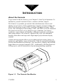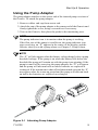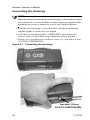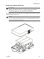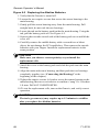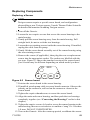
1
GENESIS
Instruction Manual
Part Number 71-0132
03Jul2008
© 2007 Thermo Fisher Scientific Inc. All rights reserved.
Specifications, terms and pricing are subject to change. Not all products are available in all countries. Please
consult your local sales representative for details.
Thermo Fisher Scientific
Air Quality Instruments
27 Forge Parkway
Franklin, MA 02038
1-508-520-0430
www.thermo.com/aqi
WEEE Compliance
This product is required to comply with the European Union’s Waste
Electrical & Electronic Equipment (WEEE) Directive 2002/96/EC. It is
marked with the following symbol:
Thermo Fisher Scientific has contracted with one or more
recycling/disposal companies in each EU Member State, and this
product should be disposed of or recycled through them. Further
information on Thermo Fisher Scientific’s compliance with these
Directives, the recyclers in your country, and information on Thermo
Fisher Scientific products which may assist the detection of substances
subject to the RoHS Directive are available at:
www.thermo.com/WEEERoHS.
Thermo Fisher Scientific
WEEE Compliance
Warranty
Seller warrants that the Products will operate or perform substantially in
conformance with Seller's published specifications and be free from defects
in material and workmanship, when subjected to normal, proper and
intended usage by properly trained personnel, for the period of time set
forth in the product documentation, published specifications or package
inserts. If a period of time is not specified in Seller’s product
documentation, published specifications or package inserts, the warranty
period shall be one (1) year from the date of shipment to Buyer for
equipment and ninety (90) days for all other products (the "Warranty
Period"). Seller agrees during the Warranty Period, to repair or replace, at
Seller's option, defective Products so as to cause the same to operate in
substantial conformance with said published specifications; provided that
(a) Buyer shall promptly notify Seller in writing upon the discovery of any
defect, which notice shall include the product model and serial number (if
applicable) and details of the warranty claim; (b) after Seller’s review, Seller
will provide Buyer with service data and/or a Return Material
Authorization (“RMA”), which may include biohazard decontamination
procedures and other product-specific handling instructions; and (c) then,
if applicable, Buyer may return the defective Products to Seller with all
costs prepaid by Buyer. Replacement parts may be new or refurbished, at
the election of Seller. All replaced parts shall become the property of Seller.
Shipment to Buyer of repaired or replacement Products shall be made in
accordance with the Delivery provisions of the Seller’s Terms and
Conditions of Sale. Consumables, including but not limited to lamps,
fuses, batteries, bulbs and other such expendable items, are expressly
excluded from the warranty under this warranty.
Notwithstanding the foregoing, Products supplied by Seller that are
obtained by Seller from an original manufacturer or third party supplier are
not warranted by Seller, but Seller agrees to assign to Buyer any warranty
rights in such Product that Seller may have from the original manufacturer
or third party supplier, to the extent such assignment is allowed by such
original manufacturer or third party supplier.
In no event shall Seller have any obligation to make repairs, replacements
or corrections required, in whole or in part, as the result of (i) normal wear
and tear, (ii) accident, disaster or event of force majeure, (iii) misuse, fault
or negligence of or by Buyer, (iv) use of the Products in a manner for which
they were not designed, (v) causes external to the Products such as, but not
limited to, power failure or electrical power surges, (vi) improper storage
and handling of the Products or (vii) use of the Products in combination
with equipment or software not supplied by Seller. If Seller determines
that Products for which Buyer has requested warranty services are not
Thermo Fisher Scientific
Warranty
covered by the warranty hereunder, Buyer shall pay or reimburse Seller for
all costs of investigating and responding to such request at Seller's then
prevailing time and materials rates. If Seller provides repair services or
replacement parts that are not covered by the warranty provided in this
warranty, Buyer shall pay Seller therefor at Seller's then prevailing time and
materials rates. ANY INSTALLATION, MAINTENANCE, REPAIR,
SERVICE, RELOCATION OR ALTERATION TO OR OF, OR
OTHER TAMPERING WITH, THE PRODUCTS PERFORMED BY
ANY PERSON OR ENTITY OTHER THAN SELLER WITHOUT
SELLER'S PRIOR WRITTEN APPROVAL, OR ANY USE OF
REPLACEMENT PARTS NOT SUPPLIED BY SELLER, SHALL
IMMEDIATELY VOID AND CANCEL ALL WARRANTIES WITH
RESPECT TO THE AFFECTED PRODUCTS.
THE OBLIGATIONS CREATED BY THIS WARRANTY
STATEMENT TO REPAIR OR REPLACE A DEFECTIVE PRODUCT
SHALL BE THE SOLE REMEDY OF BUYER IN THE EVENT OF A
DEFECTIVE PRODUCT. EXCEPT AS EXPRESSLY PROVIDED IN
THIS WARRANTY STATEMENT, SELLER DISCLAIMS ALL
OTHER WARRANTIES, WHETHER EXPRESS OR IMPLIED, ORAL
OR WRITTEN, WITH RESPECT TO THE PRODUCTS,
INCLUDING WITHOUT LIMITATION ALL IMPLIED
WARRANTIES OF MERCHANTABILITY OR FITNESS FOR ANY
PARTICULAR PURPOSE. SELLER DOES NOT WARRANT THAT
THE PRODUCTS ARE ERROR-FREE OR WILL ACCOMPLISH
ANY PARTICULAR RESULT.
Warranty
Thermo Fisher Scientific
SERVICE LOCATIONS
For additional assistance, Environmental Instruments Division has service available from
exclusive distributors worldwide. Contact one of the phone numbers below for product
support and technical information.
866-282-0430 Toll Free
508-520-0430 International
WARNING
THIS INSTRUMENT IS DESIGNED TO DETECT ONE OR MORE OF
THE FOLLOWING:
FLAMMABLE VAPORS, OXYGEN CONTENT, AND/OR TOXIC GAS AND TO
GIVE WARNING BEFORE THEY REACH HARMFUL CONDITIONS. IN ORDER
TO ENSURE THAT IT WILL WARN OF DANGEROUS CONCENTRATIONS, IT
IS ESSENTIAL THAT THE INSTRUCTIONS IN THIS MANUAL, PARTICULARLY
THOSE CONCERNING START UP , OPERATION , CALIBRATION , AND
MAINTENANCE, BE READ, UNDERSTOOD, AND FOLLOWED.
NOTATION CONVENTIONS
Notices are used in this operator's manual to alert you to hazardous conditions to person or instrument and to notify you of additional information.
This operator's manual uses the following notices.
WARNING
Notifies you of potential danger that can result in personal injury
or death.
CAUTION
Notifies you of potential damage to equipment.
NOTE
Notifies you of additional or critical information.
TABLE OF CONTENTS
Chapter 1
Introduction
About the Genesis . . . . . . . . . . . . . . . . . . . . . . . . . . . . . . . . . . . . . . . . . 1
Instrument Specifications. . . . . . . . . . . . . . . . . . . . . . . . . . . . . . . . . . . . 2
Sensor Specifications . . . . . . . . . . . . . . . . . . . . . . . . . . . . . . . . . . . . . . . 3
Optional Accessories . . . . . . . . . . . . . . . . . . . . . . . . . . . . . . . . . . . . . . . 4
Chapter 2
Start Up & Operation
Starting Up the Genesis . . . . . . . . . . . . . . . . . . . . . . . . . . . . . . . . . . . . . 5
Normal Operation . . . . . . . . . . . . . . . . . . . . . . . . . . . . . . . . . . . . . . . . . 6
Interference Factors . . . . . . . . . . . . . . . . . . . . . . . . . . . . . . . . . . . . . . . . 7
Relative Response . . . . . . . . . . . . . . . . . . . . . . . . . . . . . . . . . . . . . . . . . 8
Using the Pump Adapter . . . . . . . . . . . . . . . . . . . . . . . . . . . . . . . . . . . . 9
Using the Extender Cable . . . . . . . . . . . . . . . . . . . . . . . . . . . . . . . . . . 10
Turning Off the Genesis. . . . . . . . . . . . . . . . . . . . . . . . . . . . . . . . . . . . 11
Performing a Bump Test on Power-Up . . . . . . . . . . . . . . . . . . . . . . . . 12
Connecting the Housings . . . . . . . . . . . . . . . . . . . . . . . . . . . . . . . . . . . 14
Chapter 3
Alarms
Gas Alarms. . . . . . . . . . . . . . . . . . . . . . . . . . . . . . . . . . . . . . . . . . . . . . 15
Battery Alarms . . . . . . . . . . . . . . . . . . . . . . . . . . . . . . . . . . . . . . . . . . . 16
Sensor Alarms . . . . . . . . . . . . . . . . . . . . . . . . . . . . . . . . . . . . . . . . . . . 17
Pump Alarm . . . . . . . . . . . . . . . . . . . . . . . . . . . . . . . . . . . . . . . . . . . . . 18
Datalog Alarm . . . . . . . . . . . . . . . . . . . . . . . . . . . . . . . . . . . . . . . . . . . 19
Temperature Alarm . . . . . . . . . . . . . . . . . . . . . . . . . . . . . . . . . . . . . . . 19
Chapter 4
User Program
About the User Program . . . . . . . . . . . . . . . . . . . . . . . . . . . . . . . . . . . 21
The Display Mode . . . . . . . . . . . . . . . . . . . . . . . . . . . . . . . . . . . . . . . . 22
Accessing Password-Protected Menus. . . . . . . . . . . . . . . . . . . . . . . . . 23
Advanced Features Mode. . . . . . . . . . . . . . . . . . . . . . . . . . . . . . . . . . . 24
Edit Alarms. . . . . . . . . . . . . . . . . . . . . . . . . . . . . . . . . . . . . . . . . . . . 25
O2 Alarm Configuration. . . . . . . . . . . . . . . . . . . . . . . . . . . . . . . . . . 25
Alarm Latch Option . . . . . . . . . . . . . . . . . . . . . . . . . . . . . . . . . . . . . 26
Lunch Break Option . . . . . . . . . . . . . . . . . . . . . . . . . . . . . . . . . . . . . 26
Backlight Delay Selection . . . . . . . . . . . . . . . . . . . . . . . . . . . . . . . . 26
Cal Interval Selection . . . . . . . . . . . . . . . . . . . . . . . . . . . . . . . . . . . . 27
71-0132
vii
Advanced Features Mode (cont.)
Bump Test on Power-Up Option . . . . . . . . . . . . . . . . . . . . . . . . . . . 27
Sensor Select . . . . . . . . . . . . . . . . . . . . . . . . . . . . . . . . . . . . . . . . . . 28
HC Units Option. . . . . . . . . . . . . . . . . . . . . . . . . . . . . . . . . . . . . . . . 29
Setting AutoCal Gas Values. . . . . . . . . . . . . . . . . . . . . . . . . . . . . . . 29
Comfort Alert Options . . . . . . . . . . . . . . . . . . . . . . . . . . . . . . . . . . . 29
Temperature Alarm . . . . . . . . . . . . . . . . . . . . . . . . . . . . . . . . . . . . . 30
Enter/Edit CalWord/PassWord/LogWord . . . . . . . . . . . . . . . . . . . . 31
Exit . . . . . . . . . . . . . . . . . . . . . . . . . . . . . . . . . . . . . . . . . . . . . . . . . . 31
Datalog Features Menu . . . . . . . . . . . . . . . . . . . . . . . . . . . . . . . . . . . . 32
Adjust Date and Time. . . . . . . . . . . . . . . . . . . . . . . . . . . . . . . . . . . . 33
Edit Operator, Location, and Instrument ID’s . . . . . . . . . . . . . . . . . 33
Log Memory Manager . . . . . . . . . . . . . . . . . . . . . . . . . . . . . . . . . . . 34
Log Averages . . . . . . . . . . . . . . . . . . . . . . . . . . . . . . . . . . . . . . . . . . 35
Log Interval . . . . . . . . . . . . . . . . . . . . . . . . . . . . . . . . . . . . . . . . . . . 35
Log Status. . . . . . . . . . . . . . . . . . . . . . . . . . . . . . . . . . . . . . . . . . . . . 36
Clear Log . . . . . . . . . . . . . . . . . . . . . . . . . . . . . . . . . . . . . . . . . . . . . 36
Log Began . . . . . . . . . . . . . . . . . . . . . . . . . . . . . . . . . . . . . . . . . . . . 36
Chapter 5
Calibration
Assembling the Calbration Kit. . . . . . . . . . . . . . . . . . . . . . . . . . . . . . . 37
Calibrating the Genesis . . . . . . . . . . . . . . . . . . . . . . . . . . . . . . . . . . . . 37
Auto Calibration . . . . . . . . . . . . . . . . . . . . . . . . . . . . . . . . . . . . . . . . 38
Entering a CalWord . . . . . . . . . . . . . . . . . . . . . . . . . . . . . . . . . . . . . 39
Toxigen Calibration . . . . . . . . . . . . . . . . . . . . . . . . . . . . . . . . . . . . . 40
Manual Calibration. . . . . . . . . . . . . . . . . . . . . . . . . . . . . . . . . . . . . . 41
Calibration Alarms . . . . . . . . . . . . . . . . . . . . . . . . . . . . . . . . . . . . . . . . 43
Sensor Failed Alarm . . . . . . . . . . . . . . . . . . . . . . . . . . . . . . . . . . . . . 43
Weak Sensor Warning . . . . . . . . . . . . . . . . . . . . . . . . . . . . . . . . . . . 43
Chapter 6
Maintenance
Recharging the NiMH Battery Pack . . . . . . . . . . . . . . . . . . . . . . . . . . 45
Connecting the Housings . . . . . . . . . . . . . . . . . . . . . . . . . . . . . . . . . . . 46
Replacing Alkaline Batteries . . . . . . . . . . . . . . . . . . . . . . . . . . . . . . . . 47
Replacing Components . . . . . . . . . . . . . . . . . . . . . . . . . . . . . . . . . . . . 49
Replacing/Adding a Sensor . . . . . . . . . . . . . . . . . . . . . . . . . . . . . . . 49
Replacing the Battery Pack . . . . . . . . . . . . . . . . . . . . . . . . . . . . . . . 50
Replacing the Pump . . . . . . . . . . . . . . . . . . . . . . . . . . . . . . . . . . . . . 51
Troubleshooting . . . . . . . . . . . . . . . . . . . . . . . . . . . . . . . . . . . . . . . . . . 52
Appendix A
Parts List, Ordering Information, Replaceable Parts . . . . . . . . . . . . . . 55
Parts List, Ordering Information, Accessories. . . . . . . . . . . . . . . . . . . 56
viii
71-0132
Chapter
1
INTRODUCTION
About the Genesis
To get started with the Genesis, go to Chapter 2, Start Up & Operation. To
familiarize yourself with the Genesis, continue with this chapter.
The Genesis is a portable gas monitor that simultaneously detects and
displays up to 4 gases. It also continuously computes average readings for
Short Term Exposure Limit (STEL) and Time Weighted Average (TWA)
levels. You can display Peak readings, STEL, and TWA levels on command.
The alarm circuit alerts you to dangerous gas conditions, low battery
conditions, sensor failure, full datalog, calibration reminder, and sampledraw pump failures. The Genesis is protected by a die cast aluminum
housing with rubber end caps and a high-impact polycarbonate display
window.
A menu-driven program allows you to update and store many factory set
parameters and display various information. With the optional datalogging
version and Data Retrieval Package, you can retrieve, display, and save the
logged data on a personal computer (PC). Additionally, the Data Retrieval
Package gives you full instrument setup and programming capability.
Figure 1-1 The Genesis Gas Monitor
71-0132
1
Genesis Operator’s Manual
Instrument Specifications
Table 1-1 lists instrument specifications for the Genesis.
Table 1-1
Genesis Instrument Specifications
Housing Material
Aluminum casting with molded end caps
Regulatory Listings
UL Classified
CSA and LCIE certified for intrinsic safety
Area Classification
Class I, Division 1; Groups A, B, C and D (UL/CSA)
EEx ia D IIC T4 (LCIE)
Power Source
Battery Pack (3 AA-size Alkaline cells or NiMH)
Battery Life, without
sample-draw pump
68°F (20°C)
22 hours, alkaline
16 hours, NiMH
Battery Life, with
sample-draw pump
68°F (20°C)
11 hours, alkaline
8 hours, NiMH
Operating Temperature
-4°F to 113°F (-20°C to 45°C)
Storage Temperature
-22°F to 149°F (-30°C to 65°C)
Humidity Range
0 to 95% RH (non-condensing)
Dimensions
2.25 in. H X 3.7 in.W X 6.0 in. D
(5.62 cm X 9.25 cm X 15.0 cm)
Weight
16 ounces (454 grams)
Sampling Method
Diffusion (standard)
Sample-draw (optional internal pump)
Extender Cable (optional)
Standard Accessories
2
Operator’s manual, quick reference card, shoulder
strap
71-0132
Display Increments
1% LEL
0.1% VOL
0.1% VOL
1 PPM
1 PPM
0.1 PPM
1 PPM
1 PPM
1 PPM
0.1 PPM
0.01 PPM
0.1 PPM
HC
71-0132
HC
O2
H2S
CO
Cl2
HCN
NH3
NO
NO2
PH3
SO2
0 to 9.9 PPM
0 to 3.00 PPM
0 to 9.9 PPM
0 to 100 PPM
0 to 100 PPM
0 to 30 PPM
0 to 9.9 PPM
0 to 250 PPM
0 to 200 PPM
0 to 30.0 %VOL
0 to 5.0%VOL
0 to 100 %LEL
Range
2.0
0.3
3.0
25
25
5
0.5
25
10
19.5
0.5%VOL
10
Low Alarm
5.0
1.0
5.0
75
35
10
1.0
200
15
23.5
2.5%VOL
50
High Alarm
Genesis Sensor Specifications and Factory Default Settings
Target Gas
Table 1-2
Sensor Specifications
2.0
0.3
3.0
25
25
5
0.5
25
10
N/A
N/A
N/A
TWA Alarm
5.0
1.0
5.0
75
35
10
1.0
200
15
N/A
N/A
N/A
STEL Alarm
Introduction
3
Genesis Operator’s Manual
Optional Accessories
Table 1-3 lists optional accessories for the Genesis. See Appendix A, for
ordering information on parts and accessories...
Table 1-3
Genesis Optional Accessories
Battery pack
(NiMH or Alkaline)
Alternate battery packs are available to power the Genesis.
The NiMH battery pack is rechargeable; the alkaline
battery pack has 3 “AA” replaceable alkaline cells.
Battery charger
(NiMH)
Allows you to recharge the NiMH battery pack. Available
for 115 and 230 VAC, and 12 VDC.
Sample-draw pump
Assembly*
Used with the internal pump version of the Genesis.
Allows you to sample a remote environment. Includes
adapter cup, hose and probe with hydrophobic filter.
* Several optional hose lengths available.
Sample-draw aspirator Allows you to sample a remote environment. Uses
Assembly**
manually-operated aspirator bulb to draw sample past
sensors for non-internal pump versions.
Extender Cable
Extender cable allows for remote sensor detection. 20’ and
50’ extender cables available.
Calibration kit
Contains all equipment necessary to calibrate the Genesis.
Carrying case
Allows you to carry the Genesis and keep your hands free.
The display screen is visible through the carrying case,
and the sensors are uncovered. You can use with or
without the sample-draw accessories and extender cable.
Storage cases
Small case allows you to safely store the Genesis, battery
charger, extra battery pack, shoulder strap, and operator’s
manual. Large case stores the same as the small plus an
extender cable or sample-draw pump assembly.
Data retrieval kit
Contains program disks and appropriate cables to connect
the Genesis to a PC and retrieve the data stored in the
datalog memory. You can also edit or update all factory
default settings.
Battery Conditioning
Station
Conditions and charges up to six NiMH battery packs.
Includes power cord, specify 115 or 240 VAC operation.
NOTE
* Maximum hose length of 5’for Genesis units with Toxigen sensors.
** Not recommended for use with Toxigen sensors.
4
71-0132
Chapter
2
START UP & OPERATION
Starting Up the Genesis
Perform the following procedure to start up the Genesis.
NOTE
For NiMH versions, recharge the battery pack before you start up the
Genesis for the first time. For alkaline versions, use fresh alkaline
batteries. Wait 15 minutes for the toxic sensors to stabilize before
turning the instrument on. If the unit is started up immediately after
installing batteries, the “BIAS” message (See Note below) may appear.
See Chapter 6, Maintenance, for instructions on installing or
recharging batteries.
1. Press and hold the ON/OFF button for one second. The Genesis begins
the warm-up period. Several messages appear during the warm-up
period, starting with the model and software version. Other screens
displayed are:
• Battery capacity on a scale from E (empty) to F (full capacity) for
new alkaline or a fully charged battery pack.
• Datalogging days left for datalogging versions.
• Settings for High, Warning, STEL, and TWA alarms.
• The CAL DUE # DAYS indicates when the Genesis is due for
calibration according to the schedule you accepted in the user
program, provided the calibration interval is not set to “No CAL
Reminder”.
NOTE
During the warm-up period the Genesis determines if the toxic sensors
are properly biased. If the sensors require additional biasing, the screen
continuously displays “BIAS” with alarms instead of the gas reading.
Once the readings fall within acceptable limits, a fixed time-out is
initiated. During this time-out, the display will alternate between
“BIAS” and the sensor(s) reading. If an air adjust is performed during
this time-out period, it will not adjust the sensor(s) that are
experiencing the ‘bias time-out’ but will adjust the other sensors.
71-0132
5
Genesis Operator’s Manual
2. When the warm-up is complete, the buzzer will beep, lights will flash
several times, and display will read “WARM UP COMPLETE”.
NOTE
If the Bump Test is set to “BUMP TEST ENABLED” the display will
cue the operator to perform an “Air Adjust” and then apply test gas. See
Bump Test at the end of this chapter for instructions.
WARNING
Complete the air-adjust procedure in a “fresh air” environment
(air free of all target gases and of normal oxygen content).
3. Hold down the AIR button for 3 seconds until the display counts down
and then reads “DONE” to set the fresh air reading for all active
sensors.
NOTE
After you “Air Adjust”, a “XXX” sensor failure may appear on the
display screen. See Chapter 3, Sensor Failure, to respond to these
messages.
Normal Operation
Normal operation is defined as any time after the warm-up period is complete
and the Genesis is not alerting you to an alarm or failure.
After warm up is complete, the Genesis simultaneously displays the current
gas concentration for all active sensors and the NORM icon. This display
screen is defined as the normal screen. The sensor labels will alternate
between the gas type and unit of measure.
While in normal operation, press the BACKLIGHT button to illuminate the
display screen.
NOTE
If the Comfort Alert is enabled, the Genesis will send 2 beeps every 3
minutes to remind the operator that the unit is turned on and
functioning.This feature can be disabled or enabled by the operator, see
Chapter 4, Comfort Alert, for activating/deactivating this feature.
6
71-0132
Start Up & Operation
Interference Factors
The following factors may interfere with the sensors and produce inaccurate
readings or cause the sensor to fail.
WARNING
The flame arrestor for the hydrocarbon (HC) sensor may not be
sufficient for oxygen-rich samples.
• Oxygen-deficient samples (10% O2 or less) may cause an inaccurate
(lower) combustible gas reading.
• Very rich HC samples (above the Upper Explosive Limit) may read
close to zero. The HC reading increases to 100% LEL, then decreases
as the HC sensor is exposed to the rich sample.
• Silicone, chlorine, and fluorine compounds can “poison” the HC
sensor and cause inaccurate combustible gas readings.
Avoid exposing the HC sensor to poisonous compounds. Bump test or
calibrate the HC sensor frequently if the possibility of exposure to
poisonous compounds exists.
• The carbon monoxide (CO) sensor is sensitive to several interfering
gases (for example, hydrogen sulfide ). The sensor contains a filter to
prevent interference of some gases; however, prolonged exposure to
these gases will saturate the filter and eventually appear on the display
screen as a CO reading.
• Hydrogen, ethylene, and acetylene are strong interfering gases for the
CO sensor, and are not removed by the interference filter. Heavier
olefins and aromatic hydrocarbons are weaker interfering gases;
however, these gases may give a CO indication over time.
WARNING
LEL response will vary for different gases. For best accuracy, LEL
calibration should use the gas intended to be detected. Expected
relative combustible responses, listed in Table 2-1 are not verified
by UL.
71-0132
7
Genesis Operator’s Manual
Relative Response
The HC sensor is factory-calibrated on the gas that is listed on the packing
slip. However, the sensor responds to various hydrocarbons as shown in the
table below.
Table 2-1
Relative Response Chart for the HC Sensor
Combustible Gas
Methane Factor
Hexane Factor
Acetone
1.43
0.67
Butadiene
1.05
0.49
Carbon monoxide
0.84
0.39
Ethanol
1.27
0.59
Ethylene Oxide
1.68
0.78
Hexane/Gasoline
2.13
1.00
Hydrogen
0.90
0.42
Kerosene/Heptane
2.21
1.03
Methane
1.00
0.47
Methyl Ethyl Ketone
2.47
1.15
Pentane
2.39
1.12
Propane
1.32
0.62
2-Propanol
1.69
0.79
Propylene
1.18
0.55
Toluene
1.82
0.85
Trichloroethylene
19.20
9.00
Xylene
2.02
0.95
Please note that response varies from one sensor to another and the relative
response of a sensor can change with the age of the sensor. This data should be
used for estimation purposes only.
Assuming an instrument calibrated directly for hexane or methane but used to
observe a different gas, the equivalent response in %LEL for that gas is secured
by multiplying the observed reading by the scale conversion factor.
8
71-0132
Start Up & Operation
Using the Pump Adapter
The pump adapter attaches to the sensor end of the internal pump versions of
the Genesis. To attach the pump adapter:
1. Remove rubber end cap from sensor end.
2. Attach the cup of the pump adapter to the sensor end of the Genesis and
firmly tighten the screw, using a screwdriver if necessary.
3. Turn on the Genesis, then place the probe in the monitoring area.
NOTE
The pump indicator icon is in motion when the pump is working.
If the flow rate of the pump is insufficient, the pump indicator icon
stops revolving, an “X” appears in the center of the display, and the
Genesis alerts you with a pump alarm see Chapter 3, Pump Alarm.
NOTE
The “X” will also appear when the battery voltage drops below a pump
threshold voltage. If the pump is on when the battery falls below the
threshold the pump will remain on with the pump icon spinning. If the
pump is turned off by removing the pump adapter, the “X” will appear
and the pump will not turn back on unless batteries are replaced or
recharged. If the instrument is shut off and then turned on again the “X’
may appear after the warm-up period and the pump will not turn back
on unless the batteries are replaced or recharged.
Figure 2-1 Attaching Pump Adapter
71-0132
9
Genesis Operator’s Manual
Using the Extender Cable
The optional 20’ or 50’ extender cable attaches to any version of the Genesis.
To attach the extender cable:
1. Turn off the Genesis.
2. Loosen the two captive screws that secure the sensor housing to the
main housing.
3. Gently pull the sensor housing away from the main housing. Pull
straight back, do not rock the two housings.
4. Align the extender cable housing marked “MAIN” to the main
housing, and then push them completely together. Tighten the captive
screws by hand to secure the main housing to the end of the extender
cable (see “Connecting the Housings” at the end of this chapter).
5. Align the extender cable housing marked “SENSOR” to the sensor
housing, and then push them completely together. Tighten the captive
screws by hand to secure the sensor housing to the end of the extender
cable (see “Connecting the Housings” at the end of this chapter).
6. Finally, use a screwdriver on both connections to confirm a “snug” fit
– less than 1/8-turn. DO NOT OVERTIGHTEN.
7. Turn on the Genesis.
8. After the warm-up cycle, perform a fresh Air Adjust.
NOTE
After you “Air Adjust”, a “XXX” sensor failure may appear on the
display screen. See Chapter 3, Sensor Failure, to respond to these
messages.
9. Place the sensor housing in monitoring area.
Main housing
Sensor housing
Figure 2-2 Attaching the Extender Cable
10
71-0132
Start Up & Operation
Turning Off the Genesis
To turn off the Genesis, hold down the ON/OFF button for 3 seconds. A
power off message on the display screen counts down from 3. The Genesis
sounds a pulsing tone, and the backlight automatically turns on during the
power off sequence.
To cancel the power off command, release the ON/OFF button before the
display screen goes blank.
NOTE
The STEL, TWA, maximum, and minimum (for O2) readings are
automatically reset unless the Lunch Break mode is enabled. See
Chapter 4, Lunch Break Option for more detail.
CAUTION
If the Genesis will not be turned on for more than 2 weeks, remove
the battery pack from the instrument and the alkaline batteries
from the pack. Failure to remove the alkaline batteries prior to
storage could result in damage to the pack and/or instrument.
If rechargeable, charge the battery pack before you turn the
Genesis on.
After installing the batteries into the Genesis allow the toxic gas
sensors (if applicable) to stabilize for 15 minutes before turning the
Genesis on.
71-0132
11
Genesis Operator’s Manual
Performing a Bump Test on Power-Up
When the Bump Test option is set to “BUMP TEST ENABLED” the display
alerts the operator to perform a Bump Test after the warm-up cycle is
complete. See Chapter 4, Bump Test Option.
To perform the bump test:
1. Assemble the calibration kit. See Chapter 5, Calibration.
2. Remove the rubber end cap from the sensor end of the Genesis by
loosening the captive screw.
3. Turn on the Genesis and wait for it to complete the warm-up cycle. The
display will read “AIR ADJUST NOW”. The screen will blink on and
off with alternating lights, prompting the operator to perform a fresh
Air Adjust.
4. Press and hold the “AIR” button for three seconds until “DONE”
appears. Once the Genesis has been Air Adjusted, the display will
begin counting down, and prompt the operator to “APPLY GAS”,
alternating with “BUMP TEST”. An audible beep will sound.
NOTE
If an Air Adjust is not performed within 30 seconds, a “BUMP TEST
INCOMPLETE” message appears and the buzzer beeps on and off for
three seconds. The Genesis will return to the Normal Operating Mode.
5. Attach the calibration cup to the sensor end of the Genesis and tighten
the captive screw.
6. Turn the regulator on.
7. The Genesis should respond to the detected gas and single beep to
indicate that a Bump Test is being performed. All gas levels for
standard gases are displayed as in the Normal Operating Mode.
NOTE
If no gas is detected during the “Apply Gas” countdown, a “BUMP
TEST INCOMPLETE” message appears and the buzzer beeps on and
off for 3 seconds. The Genesis will return to Normal Operating Mode.
Once gas is detected a countdown is initiated. During this single beep
countdown the user should visually verify the sensors are responding
correctly.
12
71-0132
Start Up & Operation
NOTE
On datalogging versions, the Bump Test peak readings are recorded.
Events are recorded as “Bump Test Complete” if the Genesis detected
gas, and “Bump Test Aborted” if the Genesis did not detect gas.
A “BUMP TEST COMPLETE” message will be displayed. Then the
screen will alternate between “REMOVE GAS” and the gas readings.
Once the instrument detects the gas has been removed the screen
display an “ALARMS SILENCED” message. The alarms will be
silenced for a blind 30 second count.
After the 30 second count has elapsed an “ALARMS ACTIVE”
message will display briefly, audible alarms will be enabled and the
Genesis will return to the Normal Operating Mode.
NOTE
If the Genesis does not respond properly during the Bump Test, follow
the instructions in Chapter 5, Calibration, or Chapter 6,
Troubleshooting sections of this manual.
8. Remove the Calibration Cup and install the protective rubber endcap.
NOTE
For Toxigen instruments calibration gases are only available in singlegas cylinders. Therefore a multi-step bump process has been
programmed into the bump test routine. First, the standard sensors are
bumped using a multi-gas mixture. Then the first Toxigen sensor is
bumped using a single-gas cylinder and repeated if your unit has a
second Toxigen sensor.
For pump adapter units, (due to the sensitivity of the sensors), it is
required to perform the bump test with the pump adapter attached.
A special demand flow regulator (see parts list, Appendix A) is
required for the pump to draw the gas from the pressurized cylinder.
WARNING
Avoid using a gas mixture containing H2S for bump testing an
instrument with Cl2, NH3 or NO2 sensors.
71-0132
13
Genesis Operator’s Manual
Connecting the Housings
NOTE
When the sensor housing and the main housing (or the extender cable)
are reconnected, you must hold the sections completely together while
tightening the screws to ensure the screws don’t strip the threads.
1. Push the sensor housing (or extender cable) and the main housing
together lightly to ensure they are aligned.
2. Push the two sections together COMPLETELY then tighten the
captive screws by hand until snug to hold the sections together.
3. Finally, use a screwdriver to confirm a “snug” fit – less than 1/8-turn.
DO NOT OVERTIGHTEN.
Figure 2-3 Connecting the Housings
less than 1/8-turn
DO NOT OVERTIGHTEN
14
71-0132
Chapter
3
ALARMS
This chapter describes Genesis alarm indications, display messages, and
response for the following types of alarms:
• Gas Alarms
• Battery Alarms
• Failure Alarms
• Datalog Alarm
• Temperature Alarm
Gas Alarms
This section describes alarm indications, display messages, and response to
Low, High, STEL, and TWA gas alarms. The backlight automatically turns
during all gas alarms.
Gas Alarm Indications
Table 3-1 lists the indications for each type of gas alarm.
Table 3-1
Alarm Indications (Gas Alarms)
Alarm
Display
Light/Buzzer
Low Gas Alarm
Reading flashes
slow flashing/pulsing
High Gas Alarm
Reading flashes
fast flashing/pulsing
Decreasing O2 Alarm
Reading flashes
fast flashing/pulsing
Increasing O2 Alarm
Reading flashes
fast flashing/pulsing
STEL Gas Alarm
STEL icon
flashing/pulsing
TWA Gas Alarm
TWA icon
flashing/pulsing
71-0132
15
Genesis Operator’s Manual
Responding to Gas Alarms
1. Follow the established procedure for the type of gas alarm (Low, High,
STEL, or TWA). If a procedure is not in place, establish one that is
appropriate for your application.
2. Reset the alarm circuit. The Genesis resets the circuit according to the
alarm reset setting “LATCH AUTO” or “LATCH MANUAL”. See
Chapter 4, Alarm Latch option to enter the program and display and/or
update the setting.
• If the alarm reset setting is latch auto reset, the Genesis resets the
applicable alarm circuit after the gas reading falls below the alarm
setting (or rises above for decreasing O2).
• If the alarm reset setting is latch manual reset, press the ON/OFF
button to reset the alarm circuits after the gas reading falls below the
alarm setting (or rises above for decreasing O2).
Battery Alarms
This section describes alarm indications, display messages, and response for
the following battery alarms: Low Battery and Replace Battery. The
backlight automatically turns on during all battery alarms
Battery Alarm Indications.
Table 3-2
Alarm Indications (Battery Alarms)
Alarm
Display
Light/Buzzer
Low Battery
LOW BATTERY
double flash/beep (every two minutes)
battery icon flashes
Battery Failure
REPLACE BATTERY constant flash/beep
battery icon steady
Responding to Battery Alarms
This section describes response to Low Battery and Replace Battery alarms.
1. For Low Battery alarm, proceed to step 2 as soon as possible. The
Genesis will continue to function properly for approximately 1/2 hour
until the Replace Battery screen and alarm sounds. For battery failure
alarm, turn off the Genesis immediately. It is not functioning as a gas
detection device.
2. Recharge the NiMH battery pack or replace all 3 “AA” cells in the
alkaline battery pack. See Chapter 6, Replacing NiMH or Alkaline
Batteries.
16
71-0132
Alarms
Sensor Alarms
This section describes alarm indications, display messages, and response to
sensor failure alarms. The backlight automatically turns on during all failure
alarms.
Sensor Alarm Indications
Table 3-3 lists the indications for each type of failure alarm.
Table 3-3
Alarm Indications (Failure Alarms)
Alarm
Display
Light/Buzzer
Sensor Failure
XXX
Continuous
Responding to Sensor Alarms
A sensor failure alarm can occur during normal operation or calibration.
Alarms that occur during calibration are described in Chapter 5, Calibration.
1. Examine the display screen to determine which sensor is failing. The
failing sensor displays “XXX” instead of the gas reading for a sensor
that has failed Air Adjust or Calibration, or “XXX” in place of the gas
type for a missing sensor.
2. Turn off the Genesis.
3. Remove the two captive screws on the sides of the Genesis to access
the interior.
4. Remove the two screws from the sensor board and pull out the sensor
board. Verify that the “failing” sensor is installed properly.
5. If necessary, replace the sensor. See Chapter 6, Replacing/Adding a
Sensor.
6. You can enter the Genesis User Program and change the sensor status
setting to “OFF”. All information for an absent sensor is removed from
the normal screen and recorded as a blank in the datalog.
71-0132
17
Genesis Operator’s Manual
Pump Alarm
This section describes alarm indications, display messages, and response to
sensor, memory, and pump failure alarms. The backlight automatically turns
on during all failure alarms.
Pump Alarm Indications
Table 3-4 lists the indications for each type of failure alarm.
Table 3-4
Alarm Indications (Failure Alarms)
Alarm
Display
Light/Buzzer
Pump Failure
PUMP FAILED
→ TO RESET
pulsing/beeping (every 5 seconds)
Responding to a Pump Alarm
1. Verify that the pump adapter is properly connected to the pump fitting.
2. Check the hose, probe, and filter for flow restrictions or leaks.
3. Press the ON/OFF button to reset the alarm circuit and return to the
normal screen.
4. If the pump failure alarm continues, see Chapter 6, Replacing the
Pump, or contact Thermo Fisher Scientific for further instruction.
18
71-0132
Alarms
Datalog Alarm
This section describes the alarm indication, display message, and response for
the datalog full alarm. A datalog full alarm occurs when the datalog becomes
full and the datalog full command was accepted as STOP ON FULL.
Datalog Alarm Indications
Table 3-5 lists the indications for the datalog full alarm.
Table 3-5
Alarm
Datalog Full
Alarm Indications (Datalog Full Alarm)
Display
Light/Buzzer
LOGGING STOPPED flashing/pulsing (every 30 seconds)
Responding to the Datalog Alarm
Perform one of the following procedures to reset the datalog alarm.
• Download the data.
• Enter the datalog features menu, and update the datalog full command
to OVRWRITE ON FULL. See Chapter 4, Log Memory Manager
option.
• Enter the Datalog Features Menu and clear the datalog. See Chapter 4,
Clear Log Memory.
Temperature Alarm
The Genesis has an alarm to alert the user that the unit is being operated at a
temperature that exceeds its operating specification of -20°C to +45°C (-4°F
to +113°F). If the temperature is outside this range, the following message
appears every 30 seconds:
The buzzer beeps and lights flash twice every 30 seconds, and the condition
will clear automatically when the temperature returns to within the operating
limits.
NOTE
The temperature alarm is user enabled or disabled, with the default
setting “disabled”. See Chapter 4, Temperature Alarm.
71-0132
19
Genesis Operator’s Manual
20
71-0132
Chapter
4
USER PROGRAM
This chapter includes an introduction to the Genesis User Program and stepby-step procedures to run the program.
About the User Program
The Genesis User Program allows you to view and update factory-set
parameters and display several items, such as the battery voltage, datalog
status (capacity), current temperature, time, and date.
The menu-driven program has three main menus:
• The Display Mode
• The Advanced Features Menu
• Datalog Features Menu (for versions with optional datalogging)
The user navigates through the user program by using the three buttons: → or
ON/OFF, ↑ or AIR, and ↓ or BACKLIGHT.
• The right arrow (→) is used to accept within the menu.
• The up arrow ( ↑ ) and down arrow ( ↓ ) are used to scroll either
forward or backwards through the menu.
NOTE
The Genesis has a time-out feature. If no buttons are pressed for 10
seconds while in the Display, Advanced Features or Datalog Features
Menu the display will flash and buzzer will beep for 10 seconds. If no
buttons are pressed during this time, the Genesis will return to the
Normal Operating Mode.
71-0132
21
Genesis Operator’s Manual
The Display Mode
In the Display Mode the following may be viewed:
• Battery Capacity
• Peak Readings (Option to Clear)
• STEL Levels (Toxic Sensors Only)
• TWA Levels (Toxic Sensors Only)
• Temperature
• Date and Time
• Operator ID (Option to Change)
• Location ID (Option to Change)
• Exit
NOTE
Non-datalogging versions do not display Date and Time, Operator ID,
or Location ID screens.
To enter The Display Mode:
1. Press and hold the BACKLIGHT button for three seconds. The display
will show “DISPLAY MODE” and count down from 3 seconds. Your
first screen will display the Battery Capacity.
2. To scroll to the next screen, use the ↑ button. To scroll backwards
through the menu, press the ↓ button. Continue to scroll through the
screens to display the desired information, clear Peak Readings, or
change an Operator or User ID.
3. To exit the program, press either ↑ or ↓ until you get to the ‘EXIT’
display, then press → to exit to the Normal Operating Mode.
To change a User or Operator ID:
NOTE
Operator and Location must first be entered before a selection can be
made. See Edit Operator, Location, and Instrument ID’s.
1. For the Operator ID and Location ID screens, to change the selection
press the → button, and then use ↑ or ↓ to designate a new selection.
2. Press the → button to accept the selected ID.
NOTE
When Peak values are displayed, after three seconds the display reads
“PRESS → TO CLEAR”, so the user can clear peak values if needed.
22
71-0132
User Program
Accessing Password-Protected Menus
A password may be used to add extra security to the following menus:
• Advanced Features protected by “PASSWORD”
• Datalogging Menu protected by “LOGWORD”
• Calibration Menu protected by “CALWORD”
See Create/Edit CalWord/PassWord/LogWord for details on creating a
password. If enabled, a code must be entered before the user may enter
these menus.
To enter a PassWord, LogWord, or CalWord:
1. Press and hold ↑ and ↓ for three seconds. The message “FEATURES
MODE” appears on the display and counts down from 3 seconds, and
then displays “BEGIN CAL”. Continue and press ↓ to scroll to
“ADVANCED FEATURES” or “DATALOG MENUS”.
2. Stop scrolling at the desired screen and press → to accept. The display
now reads “PASSWORD”, “LOGWORD”, or “CALWORD” and “* *
*” (if protection has been enabled). The cursor is on the first asterisk.
NOTE
If the “***” does not appear when entering any of the three modes,
security protection is not enabled.
3. Press ↑ or ↓ to scroll to the correct character.
4. Press → to accept. The cursor moves to the next character.
5. Repeat steps 4 and 5 until all three characters are accepted. If your
entry is correct, you will advance to the next screen . If your entry is
incorrect, you will return to the original screen. Begin at step 2 to retry
your password.
71-0132
23
Genesis Operator’s Manual
Advanced Features Mode
The Advanced Features Mode allows you to change the parameters of the
instrument. The factory default value is indicated after the menu title in
parenthesis.
The menu is as follows:
• Edit Alarms
• O2 Alarm Configuration
• Alarm Latch Option
• Lunch Break Option
• Backlight Delay Selection
• Calibration Interval Selection
• Bump Test Option
• Sensor Select
• HC Units Option
• Setting Auto Cal Gas Values
• Comfort Alert Options
• Temperature Alarm
• Pump Threshold
• Change Cal Word
• Change Password
• Change Logword
• Exit
To enter the Advanced Features Mode:
1. Press and hold both the AIR and BACKLIGHT buttons for three
seconds. The screen displays “FEATURES MODE” and counts down
from 3.
2. The first screen displayed after the countdown is “BEGIN CAL”. Press
the ↓ button, then press the → button. If prompted by “PASSWORD”
and “***”, enter a password as described in the previous section,
Accessing Password-Protected menus. When entered correctly, or if
PassWord is not enabled, you are now at the first option “EDIT
ALARMS” in the Advanced Features Menu.
24
71-0132
User Program
NOTE
The Genesis has a time-out feature. While in the Advanced Features
Mode, if a button is not pressed within 10 seconds the display will flash
and the buzzer will beep for 10 seconds. If no button is pressed during
the 10 seconds, the Genesis will return to normal mode.
EDIT ALARMS
This allows the user to increase or decrease the High and Low Alarms for
each gas. See Chapter 1, Sensor Specifications for factory default settings.
1. Press → to enter the HC screen. The high alarm reading will flash.
2. Press ↑ or ↓ to increase or decrease the alarm setting. If you choose to
keep the alarm as is, press → to move to the next alarm setting.
3. Continue step 2 until you have set all gas alarms. After the last gas
alarm is set, the display automatically returns to the “EDIT ALARMS”
screen.
NOTE
You will scroll through the following gas alarms, appropriate to your
version of Genesis: HC, O2, TOXIC1, TOXIC2.
4. Press ↑ or ↓ to continue scrolling through the Advanced Features Menu.
O2 ALARM CONFIGURATION
This option allows you to set the oxygen alarms (High and Low) to either
increasing or decreasing.
Options you can choose are:
• ONE INC/ONE DEC - The warning alarm is set to decreasing at
19.5%VOL and high alarm increasing at 23.5%VOL.
• TWO ALRM/DECREASE - Both alarms are set to decrease. Warn at
19.5%VOL and High at 18.0%VOL.
• TWO ALRM/INCREASE - Both alarms are set to increase. Warn at
22.5%VOL and high at 23.5%VOL.
The factory default setting is “ONE INC/ONE DEC”.
To enter this mode from the Advanced Features Mode:
1. Press → to accept “O2 ALARM CONFIG”.
2. Press ↓ or ↑ to scroll through the settings. Press the → to accept the
setting.
3. Press ↓ to continue scrolling through the Advanced Features Menu.
71-0132
25
Genesis Operator’s Manual
ALARM LATCH OPTION
This option changes the alarm setting to either automatic reset (LATCH
AUTO) or latching (LATCH MANUAL). The factory default setting is
“AUTO RESET”.
1. Press → to accept “ALARM LATCH”.
2. Press ↓ or ↑ to scroll between settings. Press → to accept the setting.
3. Press ↓ to continue scrolling through the Advanced Features Menu.
LUNCH BREAK OPTION
The lunch break option allows the user to either reset averages (STEL and
TWA) or retain averages when the Genesis is turned off. The factory default
setting is “RESET AVERAGES”.
NOTE
If the lunchbreak mode is set to “RETAIN AVERAGES”, the Genesis
will retain the STEL and TWA averages when turned off. If the
lunchbreak mode is set to “RESET AVERAGES”, the Genesis will
reset the averages when turned off.
To change the lunch break mode from the Advanced Features Menu:
1. Press → at the screen “LUNCH BREAK”.
2. Press ↓ or ↑ to scroll through the settings. Press → to accept the
setting.
3. Then press ↓ to continue scrolling through the Advanced Features
Menu.
BACKLIGHT DELAY SELECTION
The backlight delay feature sets the number of seconds the backlight is
illuminated after the “BACKLIGHT” button is pressed. The factory default is
setting is 5 seconds. Your options are in 5 second increments up to 60
seconds, and 2, 3, 5, or 10 minutes.
To change the backlight delay setting from the Advanced Features Menu:
1. Press → at the screen “BKLIGHT DELAY”.
2. Press ↓ or ↑ to scroll through the settings. Press → to accept the
setting.
3. Then press ↓ to continue scrolling through the Advanced Features
Menu.
26
71-0132
User Program
CAL INTERVAL SELECTION
This sets the number of days between calibrations.
NOTE
The number of days left until calibration is displayed during the warmup cycle. When the Genesis is due for calibration, display reads “CAL
OVERDUE” and buzzer and lights, pulse and flash after the warm-up
cycle is complete.
Your options are No CAL Reminder, 1 to 6 one-day increments and 1 to 26
one-week increments. The factory default setting is “NO CAL REMINDER”,
which means the calibration reminder function is turned off.
NOTE
For optimum performance, calibrate the Genesis before every use.
To change the calibration reminder setting from the Advanced Features
Menu:
1. Press → at the screen “CAL INTERVAL”.
2. Press ↓ or ↑ to scroll through the settings.
3. Press → to accept the setting.
4. Then press ↓ to continue scrolling through the Advanced Features
Menu.
BUMP TEST ON POWER-UP OPTION
The Bump Test Option enables or disables the Genesis to cue the user to
apply gas for a Bump Test immediately after the Genesis warm-up cycle is
complete. The factory default setting is “BUMP TEST DISABLED”.
To change the bump test setting from the Advanced Features Menu:
1. Press → at the screen “BUMP TEST”.
2. Press ↓ or ↑ to scroll between “BUMP TST DISABLED” to “BUMP
TST ENABLED”.
3. Press → to accept the setting.
4. Then press ↓ to continue scrolling through the Advanced Features
Menu.
71-0132
27
Genesis Operator’s Manual
SENSOR SELECT
The sensor select function turns the sensor(s) on or off for HC and O2, and for
toxic sensors, also allows you to select the sensor type installed for the
remaining sensor(s). When any gas other than “OFF” is selected the sensor
readings and averages are shown during Normal Operation and in the Display
Mode.
WARNING
The Genesis does not display gas readings, initiate alarms,
compute averages, or store data for “OFF” sensor(s).
To change the sensor select setting from the Advanced Features Menu:
1. Press → at the screen “SENSOR SELECT”. All four gases and their
settings will display. The cursor and reading will flash for HC.
2. Press ↑ or ↓ to change the setting to “ON” or “OFF”. If you choose to
keep the setting, as is, press → to move on to the O2.
3. Repeat step 2 for O2, press → to move on to the H2S (Toxic 1) sensor.
CAUTION
The selected gas type(s) in the Sensor Select screen must match the
sensor type installed in the H2S (Toxic 1) and CO (Toxic 2)
locations or improper calibration and false readings are likely to
occur.
4. Press ↑ or ↓ to select/change the gas type or to turn the sensor “OFF”.
If you choose to keep the setting, as is press to move on to the CO
(Toxic 2) sensor.
5. Repeat step 4 for CO (Toxic2), press → to accept the setting and exit
back to the Advanced Features menu.
NOTE
You will scroll through the following sensor selections, appropriate to
your version of Genesis: HC, O2, H2S (Toxic 1), CO (Toxic 2).
28
71-0132
User Program
HC UNITS OPTION
This function changes the hydrocarbon units to be displayed in either %LEL
or %VOL. The factory default setting is “%LEL”.
To change the hydrocarbon units setting from the Advanced Features Menu:
1. Press → at the screen “HC UNITS”.
2. Press ↓ or ↑ to scroll between “%LEL” to “%VOL”.
3. Press → to accept the setting.
4. Press ↓ to continue scrolling through the Advanced Features Mode.
SETTING AUTOCAL GAS VALUES
This function allows you to set the auto calibration values to the concentration
of the cylinders you are using.
NOTE
The factory default settings for a standard four gas instrument are HC
50%LEL, O2 12.0%VOL, H2S 25 PPM, and CO 50 PPM. These are
the values that match Thermo Scientific’s multi-gas cylinders.
To change the value(s) from the Advanced Features Menu:
1. Press → at the screen “AUTOCAL GAS VAL”. All four gases and
their values will display. The cursor and reading will flash for HC.
2. Press ↑ or ↓ to change value up or down.
3. Once you’ve reached the desired value, press → to move on to the O2.
If you choose to keep the setting, as is, press → to move on to the next
sensor.
4. Continue this process through all gases.
NOTE
You will scroll through the following autocal gas values, appropriate to
your version of Genesis: HC, O2, TOXIC1, TOXIC2.
COMFORT ALERT OPTIONS
The comfort alert is a friendly reminder that the instrument is on and working.
The reminder begins 3 minutes after the last button press and will sound every
3 minutes while in the Normal Operating Mode. The alert has four options:
• Beep Only - Every three minutes the buzzer sounds.
• Blink Only - Every three minutes the lights flash.
• Blink and Beep- Both buzzer beeps and lights flash every three
minutes.
• Both Off - Option disabled.
71-0132
29
Genesis Operator’s Manual
The factory default setting is “BLINK AND BEEP”.
NOTE
The 3 minute comfort alert timer is reset after any button is pressed by
the user.
To change the setting from the Advanced Features Menu:
1. Press → at the screen “COMFORT ALERT”.
2. Press ↓ or ↑ to scroll through the options.
3. Press → to accept the setting. Press ↓ to continue scrolling through the
Advanced Features Menu.
TEMPERATURE ALARM
The Genesis has an alarm to alert the user that the Genesis is being operated
at a temperature that exceeds its operation specification of -4ºF to 113ºF
(-20ºC to 45ºC). When the temperature alarm is activated, the buzzer and
lights are on continuously. The factory default setting is “TEMP ALARM
DISABLED”.
To change the setting from the Advanced Features Menu:
1. Press → at the screen “TEMP ALARM”.
2. Press ↓ or ↑ to change to either “TEMP ALR DISABLED” or “TEMP
ALR ENABLED”.
3. Press → to accept the setting.
4. Press ↓ to continue scrolling through the Advanced Features Menu.
SELECTING PUMP THRESHOLD
This setting allows the operator to adjust the low flow threshold for different
pump current. The default setting is “LOW”, and the setting normally is only
changed when the pump is replaced.
1. Press → at the screen “PUMP THRESHOLD”.
2. Press ↑ or ↓ to change the setting to either “PUMP LOW
THRESHOLD” or “PUMP HI THRESHOLD”.
3. Press → to accept the setting.
4. Press ↑ to continue scrolling through the Advanced Features Menu.
30
71-0132
User Program
ENTER/EDIT CALWORD, PASSWORD, OR LOGWORD
These options add extra security to the calibration process (CALWORD),
Advanced Features Menu (PASSWORD), and Datalog Features Menu
(LOGWORD). By changing the default factory setting of “***”, you
automatically turn this option on, and password protect that area of the
program. If turned on, a code must be entered before one may continue a
process. If “***” is entered, the password security is turned off . The factory
default setting for each password is “***”, or disabled.
To add or change the code from the Advanced Features Menu,
1. Press → at the appropriate screen “CHANGE CALWORD”,
“CHANGE PASSWORD” or “CHANGE LOGWORD”. The screen
will display either three asterisks “***”, or the three digit code, with
the cursor on the first character.
2. Press ↓ or ↑ to change the first character of the code. You have the
option of “*, 0 through 9”.
NOTE
When entering a CalWord, PassWord, or LogWord all three characters
must be a number, 0 through 9. A password containing one or more “*”
is not valid, no security protection is implemented if a password
contains an “*”.
3. Press → to accept the setting, and move on to the second character. If
you do not want to change the first character, press → to move on to
the second character.
4. Repeat the process through the third character.
5. Press ↓ to continue scrolling through the Advanced Features Menu.
EXIT
The ‘EXIT’ screen exits you from the Advanced Features Mode. Press → at
“EXIT” to return to the Normal Operating Mode.
71-0132
31
Genesis Operator’s Manual
Datalog Features Menu
All Genesis versions with optional datalogging include this menu.
The menu is as follows:
• Adjust Date and Time
• Edit Operator IDs
• Edit Location IDs
• Instrument ID
• Log Memory Manager Option
• Log Averages Selection
• Log Interval Selection
• View Log Status
• Clear Log Memory
• View Log Began
• Exit
To enter the Datalog Features Mode:
1. Press and hold both the AIR and BACKLIGHT buttons for three
seconds. The screen displays “FEATURES MODE” and counts down
from 3 seconds.
2. The first screen displayed after the countdown is “BEGIN CAL”. Press
the ↓ button twice. The display will read “DATALOG MENUS”.
3. Press the → button. If prompted by “LOGWORD” and “***”, enter a
LogWord as described earlier in this chapter. When entered correctly,
or if LogWord is not enabled, you are now at the first option “ADJUST
DATE AND TIME”.
NOTE
The Genesis has a time-out feature. While in the Advanced Features
Mode, if a button is not pressed within 10 seconds the display will flash
and the buzzer will beep for 10 seconds. If no button is pressed during
the 10 seconds, the Genesis will return to The Normal Operating Mode.
32
71-0132
User Program
ADJUST DATE AND TIME
The date and time are adjustable by the user. The default factory settings are
Pacific Standard Time. The Genesis uses a 24-hour format to display time.
For example, 21:30:00 is 9:30 PM.
To change the date and time from the Datalog Menu:
1. Press → at the screen “ADJ DATE AND TIME”. The date and time
will appear, with the cursor on the month that is flashing.
2. Press ↑ or ↓ to change to the correct month. Once you’ve reached the
correct value, press → to move to the day of the month. If you choose
to keep the setting, as is, press → to move to the year.
3. Continue this process through remaining date and time settings. Once
you’ve completed and pressed → past the seconds, the “ADJ DATE
AND TIME” screen displays, and your selection has been accepted.
EDIT OPERATOR, LOCATION, AND INSTRUMENT IDS
The ID’s are used to indicate the Operator and Location of personal when
exposed to gases. The information is stored in the datalogging memory for
retrieval at a later time. The Genesis has three IDs the user can update:
• The Operator ID screen allows the Genesis to reference logged data
with 16 different operator codes.
• The Location ID screen allows the Genesis to reference logged data
with 64 different location codes.
• The Instrument ID screen allows you to uniquely identify the
Genesis.
The Operator and location IDs are a two row, 8 characters per row, field. Each
character accepts A-Z, a-z, 0-9, asterisk (*), and blank space. The Genesis
User Program stores up to 16 Operator and 64 Location IDs.
Each Operator ID is uniquely referenced by a number from 1 to 16. Each
Location ID is referenced by a number from 1 to 64. You can accept (and
record in the datalog) an Operator and/or Location ID by its reference number
See Chapter 4, Display Mode.
To add or change the Operator and Location ID from the Datalog Menu:
NOTE
The factory default setting for Operator, Location, and Instrument IDs
are blank.
71-0132
33
Genesis Operator’s Manual
1. Press → at the appropriate screen “EDIT OPER IDs”, “EDIT LOC
ID”, or ““INST ID”. The first ID screen will appear, you can change
this screen by pressing → to accept and start editing this ID or you can
press ↑ or ↓ to scroll through the other ID screens. Then press → to
accept.
2. Press ↓ or ↑ to change the first character of the ID. You have the option
of “*, 0 - 9, A-Z, a-z, and blank”.
3. Press → to accept the character or space, and move to the next
character. If you do not want to change the first character, press → to
move to the next character.
4. Repeat the process through both rows of characters.
5. Press ↓ to continue scrolling through the Datalog Menu.
NOTE
For the Operator ID and Location ID screens, the ID’s reference
number is displayed on the bottom line. Press the ↑ button to continue
scrolling through the various operators and locations you want to
display or update. Then press → to edit or update the screen.
LOG MEMORY MANAGER
This instructs the datalog memory to either overwrite the oldest data,
“OVRWRITE ON FULL”, or stop recording data, “STOP ON FULL”, when
the memory is full. The factory default setting is “OVRWRITE ON FULL”.
NOTE
If you accept “STOP ON FULL”, the Genesis alerts you with a datalog
full alarm when the Genesis is no longer recording data. See Chapter 3,
Alarms. If you accept “OVRWRITE ON FULL”, the Genesis begins
writing over the oldest data when the datalog is full. The overwritten
data is not retrievable.
To change the setting, from the Datalog Features Menu:
1. Press → at the screen “LOG MEM MANAGER”.
2. Then press ↑ or ↓ to display the correct setting.
3. Press → to accept the setting.
4. Then press → to continue scrolling the Datalog Features Menu.
34
71-0132
User Program
LOG AVERAGES
This parameter controls which averages (STEL or TWA) the Genesis stores
in the datalog. Available selections for each toxic sensor that is active are:
• LOG ALL - Log both STEL and TWA
• LOG TWA ONLY - Log TWA only
• LOG STEL ONLY - Log STEL only
• NO AVE LOGGING - Neither STEL or TWA are logged
The factory default setting is “LOG ALL”.
To change the setting for logging STEL and TWA from the Datalog Features
Menu:
1. Press → at the screen “LOG AVERAGES”.
2. Press ↓ or ↑ to scroll between options until you get to the appropriate
screen.
3. Press → to accept the setting.
4. Press ↓ to continue scrolling through the Datalog Features Menu.
LOG INTERVAL
This parameter instructs the Genesis how often to record data in the datalog.
You have the option of 5, 15, 30, 60, 90, 300, or 900 seconds. The factory
default setting is “LOG EVERY 60 SECONDS”.
To change the setting for log interval from the Datalog Features Menu:
1. Press → at the screen “LOG INTERVAL”.
2. Press ↓ or ↑ to scroll between options until you get to the appropriate
screen.
3. Press → to accept the setting.
4. Press ↓ to continue scrolling through the Datalog Features Menu.
Table 4-1 illustrates approximately how long it takes to fill the datalog for
common datalog interval settings.
Table 4-1
Datalog Capacity Specifications
71-0132
Sample Interval
Capacity (No Alarm Activity)
5 seconds
18 hours
15 seconds
55 hours
30 seconds
111 hours
60 seconds
9 days
90 seconds
13 days
300 seconds
36 days
900 seconds
108 days
35
Genesis Operator’s Manual
LOG STATUS
This is a display screen only, which indicates the number of datalog hours or
days left in memory that is not currently occupied.
To display the number of hours or days left, from the Datalog Features Menu:
1. Press → at the screen “LOG STATUS”. The screen displays reads
“XX LOG HRS LEFT” or “XX LOG DAYS LEFT” (“XX” for
number of hours or days available in memory). The display will
automatically go back to the “LOG STATUS” screen.
2. Press ↑ or ↓ to continue scrolling the Datalog Menu.
CLEAR LOG
To clear the data in the memory, from the Datalog Features Menu:
1. Press → at the screen “CLEAR LOG”. The screen displays “ ↑ AND
↓ TO CLEAR”.
2. Press and hold ↑ and ↓ for three seconds. The display reads
“CLEARING LOG” and beeps for several seconds. When complete
the display indicates “LOG CLEARED”.
NOTE
If you do not want to clear the log, press the → button and continue
scrolling through the Datalog Features Menu.
CAUTION
You cannot recover data after you clear the log. Download all
required data before you clear the log.
LOG BEGAN
This screen displays the date and time when the log was last cleared.
To display this data and time, from the Datalog Menu:
1. Press → at the screen “LOG BEGAN”. The screen displays the data
and time. For example, “7/12/99 10:00:00”. The display automatically
goes back to the “LOG BEGAN” screen.
2. Press ↑ or ↓ to continue scrolling on the Datalog Menu.
EXIT
The ‘EXIT’ screen exits you from the Datalog Features Mode. Press → to exit
the menu and return to the Normal Operating Mode.
36
71-0132
Chapter
5
CALIBRATION
This chapter describes steps necessary to assemble the calibration kit and
calibrate the Genesis. Alarms that may occur during calibration are described
at the end of this chapter.
NOTE
For optimum performance, calibrate the Genesis before every use.
During calibration, on datalogging versions, datalogging is disabled.
Assembling the Calibration Kit
1. Verify that the regulator is closed, then carefully screw the regulator
into the gas cylinder.
2. Attach the sample tubing over the fitting on the regulator.
3. Attach the other end of the sample tubing to the calibration cup.
Calibrating the Genesis
The Genesis offers two calibration options, automatic and manual.
• The automatic calibration (AUTO CAL) displays all active
sensors on the display screen at the same time. You can calibrate all
active sensors simultaneously using a multi-gas cylinder available
from Thermo Fisher Scientific. The concentrations set in the Auto
Cal Gas Value screen must match the multi-gas mixture. See
Chapter 4, Setting Auto Cal Gas Values.
• During the manual calibration (MAN CAL) only one active sensor
is displayed on the screen at a time, only one sensor is calibrated
during a manual calibration. It is recommended to use a single gas
cylinder for manual calibrations. During a manual calibration you
may manually change the concentration of the gas before the gas is
applied. The default value is that set in the Auto Cal Gas Values
screen. See Chapter 4, Setting Auto Cal Gas Values.
71-0132
37
Genesis Operator’s Manual
Auto Calibration
NOTE
If you use the automatic adjustment method to calibrate the sensor,
make sure the gas cylinder contains the same concentrations of the
target gas as the values set in the “AUTOCAL GAS VAL” menu. See
Chapter 4, Setting Auto Cal Gas Values.
1. In a “fresh air” environment (known to be free of all target gases and of
normal oxygen content), hold down the AIR button for 3 seconds until
the display reads “DONE” to set the zero reading for all active sensors
(20.9 for O2).
NOTE
After you complete the fresh air adjustment, a “XXX” may appear on
the display screen in place of a sensor reading. The buzzer and lights
will be on steady. See Calibration Alarms section at the end of this
chapter to respond to this message.
2. Remove the rubber end cap from the sensor end of the Genesis by
loosening the captive screw.
3. Attach the calibration cup to the sensor end of the Genesis and tighten
the captive screw.
4. Press and hold ↑ and ↓ for three seconds. The “FEATURES” mode
counts down from 3, then displays “BEGIN CAL”.
5. Press →to accept and begin a calibration. If a CalWord has not
enabled, the “AUTO CAL” screen is displayed. Skip the next section
and proceed with Calibrating with the Auto Cal Screen (cont.) on the
following page.
NOTE
If prompted by “CALWORD” and “***”, enter a password as
described in the next section.
38
71-0132
Calibration
Entering a CalWord
A password may be used to add extra security to the Calibration with a
“CALWORD”. See Chapter 4, Create/Edit CalWord/PassWord/LogWord. If
turned on, a code must be entered before the user may perform a calibration.
To enter a CalWord (if activated):
1. Press and hold ↑ and ↓ for three seconds. The message “FEATURES
MODE” appears on the display and counts down from 3, and then
displays “BEGIN CAL”.
2. Press → to accept. The display reads “CAL WORD” and “* * *”. The
cursor is on the first asterisk.
3. Press ↑ or ↓ to scroll to the correct character.
4. Press → to accept. The cursor moves to the next character.
5. Repeat steps 3 and 4 until all three characters are accepted. If correct,
the next display reads “AUTOCAL”. If the CalWord is incorrect, the
display reads “BEGIN CAL” message. Begin at step 2 to start over.
Auto Calibration (cont.)
6. Press → to accept “AUTO CAL”. The screen displays “BEGIN
AUTOCAL” alternating with “APPLY GAS” counting down from 30
seconds. If no gas is detected during this period, the screen returns to
“BEGIN CAL”.
7. Turn on the regulator and wait for the Genesis to go through the
process.
First, the display will read “CAL IN PROCESS” for the first 30
seconds. Then the screen displays “CAL TIME LEFT” (counting
down from 45 seconds) alternating with the gas readings.
NOTE
During calibration, on datalogging versions, datalogging is disabled
but calibration events are recorded in the logged data.
8. When calibration is complete, the display reads “AUTOCAL
PASSED” and then alternates between “>ACCEPT, ABORT” and the
gas readings. The gas labels alternate with ‘PASS”. Press → to accept.
The display will show “CAL ACCEPTED”, and then alternate
between “REMOVE GAS” and the gas readings.
If you choose to abort, press ↓ to scroll to “ABORT” then → to accept
the abort option.
The display will read “CAL ABORTED” and then alternate between
“REMOVE GAS” and the gas readings.
71-0132
39
Genesis Operator’s Manual
NOTE
The “WEAK” or “FAIL” flag may appear in place of the “PASS” flag
in the case of a weak or failed sensor. See the instructions in the
Calibration Alarms section, later in this chapter for corrective action.
9. Turn the regulator off and remove the calibration cup, reattach the
rubber end cap to the Genesis. The display will alternate between
“ALARMS SILENCED”, and the readings, and then return to the
Normal Operating Mode, after an “ALARMS ACTIVE” message is
displayed.
10. Unscrew the regulator from the cylinder. Leave the components of the
calibration kit assembled for convenience. Store the kit in the storage
case.
Toxigen Calibration
The Toxigen calibration gases are only available in single-gas cylinders.
Therefore a multi-step calibration process has been programmed into the
calibration routine. First, the standard sensors are calibrated using a multi-gas
mixture. Then the first Toxigen sensor is bumped using a single-gas cylinder,
and repeated if your unit has a second Toxigen sensor.
NOTE
For pump adapter units, (due to the sensitivity of the sensors), it is
required to perform the calibration with the pump adapter attached.
A special demand flow regulator (see parts list, Appendix A) is
required for the pump to draw the gas from the pressurized cylinder.
1. Begin the calibration process by performing an Auto Calibration from
the beginning. The Toxigen sensors will be ignored during the multigas calibration.
2. When the multi-gas calibration is complete, a double beep prompts the
user to begin the first Toxigen sensor calibration. The default gas
concentration is displayed with the ADJ icon to indicate you may
change the concentration.
3. Press to begin the calibration.
4. Apply the calibration gas and follow the prompt to complete the
calibration process. When the first Toxigen is complete, and a second
Toxigen sensor is present, a double beep prompts the user to begin the
second Toxigen sensor calibration.
40
71-0132
Calibration
WARNING
Avoid using a gas mixture containing H2S for calibrating an
instrument with Cl2, NH3 or NO2 sensors.
Manual Calibration
1. In a “fresh air” environment (known to be free of all target gases and of
normal oxygen content), hold down the AIR button for 3 seconds until
the screen displays “DONE” to set the zero reading for all active
sensors (20.9 for O2).
NOTE
After you complete the fresh air adjustment, a “XXX” may appear on
the display screen in place of a sensor reading. The buzzer and lights
will be on steady. See the Calibration Alarms section at the end of this
chapter to respond to this message.
2. Remove the rubber end cap from the sensor end of the Genesis by
loosening the captive screw.
3. Attach the calibration cup to the sensor end of the Genesis and tighten
the captive screw.
4. Press and hold ↑ and ↓ for three seconds. The “FEATURES” mode
counts down from 3. Then displays “BEGIN CAL”.
5. Press → to accept and begin calibration. If a Calword has not enabled,
the “AUTO CAL” screen is displayed.
NOTE
If prompted by “CALWORD” and “***”, enter a password, see
Entering CalWord earlier in this chapter.
6. With the “AUTO CAL” message displayed. Press the ↓ to advance to
the “MAN CAL” screen. Press → to accept “MAN CAL”.
7. The screen displays the first active sensor. Press the → to accept or
press ↓ to advance to the next gas depending on what sensor you want
to calibrate. To accept the desired selection, press →.
8. The default gas concentration is displayed with the ADJ icon and a
double beep to indicate you may change the default concentration. The
default concentration is set in the Auto Cal Gas Value. See Chapter 4,
Setting Auto Cal Gas Values.
9. Press ↑ and ↓ to adjust the value to match the concentration of the
calibration gas as read on the cylinder label.
71-0132
41
Genesis Operator’s Manual
10. Press → to accept the displayed concentration. The display reads
“BEGIN MAN CAL” alternating with “APPLY XX GAS” (where XX
is the gas selected) and counts down from 45 seconds. If no gas is
detected during this period, the screen returns to “BEGIN CAL”.
11. Turn on the regulator, then wait for the Genesis to go through the
process.
First, the display will read “CAL IN PROCESS” for 30 seconds , with
the SPAN icon on. Then the screen displays “CAL TIME LEFT”
(counting down to 0 seconds) alternating with the gas reading.
NOTE
During calibration, on datalogging versions, logging is disabled but
calibration events are recorded in the log.
12. When calibration is complete, the display reads “MAN CAL
PASSED” and then alternates between “>ACCEPT, ABORT” and the
gas reading. The gas label alternates with “PASS”.
13. Press → to accept. The display will show “CAL ACCEPTED”, and
then alternate between “REMOVE GAS” and the all active sensors gas
readings.
NOTE
If the calibration gas used interferes with any of the other sensors a
non-zero reading may result, this does not affect the calibration of those
sensor(s).
14. If you choose to abort, press ↓ to scroll to “ABORT” then → to accept
the abort option. The display will read “CAL ABORTED” and then
alternate between “REMOVE GAS” and all active sensor gas
readings.
NOTE
The “WEAK” or “FAIL” flag may appear in place of the “PASS” flag
in the case of a weak or failed sensor. See the instructions in the Sensor
Failed Alarms section later in this chapter for corrective action.
15. Turn the regulator off, remove the calibration cup, and reattach the
rubber end cap to the Genesis. The display will alternate between
“ALARMS SILENCED”, and the readings, and then return to the
Normal Operating Mode, after an “ALARMS ACTIVE” message is
displayed.
16. Repeat steps 6, 7, and 8 until all required sensors are calibrated.
17. Unscrew the regulator from the cylinder. Leave the components of the
calibration kit assembled for convenience. Store the kit in the storage
case.
42
71-0132
Calibration
Calibration Alarms
The Genesis may alert you to one or more of the following alarms during
calibration:
• Sensor Failed Alarm
• Weak Sensor
• Calibration Incomplete
Sensor Failed Alarm
If you attempt to air adjust or calibrate a failed sensor, the Genesis alerts you
with a Sensor Failed Alarm.
INDICATIONS
• The backlight turns on automatically.
• The gas reading is replaced by XXX.
• Lights and Buzzer are steady.
RESPONDING TO A SENSOR FAILED ALARM
1. Complete the calibration procedure for the remaining sensors (if
applicable), then return to the normal screen. The normal screen will
continue to notify you of the sensor failure with a message.
2. Turn off the Genesis, then verify that the sensor is installed properly.
See Chapter 6, Replacing/Adding a Sensor. Verify that the calibration
gas value is correct.
3. If the calibration gas value is correct, and the sensor is installed
properly, turn the instrument on and repeat the air adjust and
calibration procedures.
4. If the Fail condition persists, replace the sensor. See Chapter 6,
Replacing/Adding a Sensor, then calibrate the new sensor.
NOTE
You can enter the Genesis User Program, Advanced Features Menu,
and change the sensor status setting to “OFF”. All information for an
“OFF” sensor is removed from the normal screen and recorded as a
blank in the datalog.
Weak Sensor Warning
If the sensor that you are calibrating is nearing the end of its useful life, the
Genesis alerts you with a Weak Sensor message.
71-0132
43
Genesis Operator’s Manual
INDICATIONS
• The gas flag will show “WEAK” at the conclusion of the calibration
period.
RESPONDING TO A WEAK SENSOR
1. If you are manually calibrating the Genesis, verify that you are
correctly adjusting the gas concentration to match the concentration of
the calibration gas. If using the Auto Cal method, verify that the gas
concentration in the calibration gas cylinder matches the Auto Cal Gas
Value. See Chapter 4, Setting Auto Cal Gas Values.
NOTE
A weak sensor is still functioning properly and can continue to be used.
However, it is near the end of its useful life, and should be replaced as
soon as possible. See Chapter 6, Replacing/Adding a Sensor, for
replacement instructions.
44
71-0132
Chapter
6
MAINTENANCE
This chapter includes component replacement and troubleshooting
procedures for the Genesis.
Recharging the NiMH Battery Pack
WARNING
Recharge the battery pack only in a non-hazardous environment.
CAUTION
Due to the nature of high capacity NiMH batteries, keep the
Genesis on charge when not in use.
1. Verify that the Genesis is turned off.
2. Remove the rubber end cap from the sensor end of the Genesis by
loosening the captive screw.
3. Attach the charger boot to the back of the Genesis, and tighten the
thumbscrew. Plug the battery charger into an applicable outlet.
The amber light on the battery charger turns on when the battery
charger begins recharging the battery pack.
CAUTION
Use only the battery chargers listed in Appendix A, Parts List, to
recharge the battery pack.
4. When the battery pack is fully recharged, the green light turns on (the
amber light remains on.)
A completely depleted battery pack recharges in approximately 3
hours. The battery charger automatically cuts the charging current to a
sustaining rate when the battery pack is fully charged.
To maintain a fully charged battery, leave the battery charger plugged
into the Genesis until you are ready to operate the Genesis.
71-0132
45
Genesis Operator’s Manual
Connecting the Housings
NOTE
When the sensor housing and the main housing (or the extender cable)
are reconnected, you must hold the sections completely together while
tightening the screws to ensure the screws don’t strip the threads.
1. Push the sensor housing (or extender cable) and the main housing
together lightly to ensure they are aligned.
2. Push the two sections together COMPLETELY then tighten the
captive screws by hand until snug to hold the sections together.
3. Finally, use a screwdriver to confirm a “snug” fit – less than 1/8-turn.
DO NOT OVERTIGHTEN.
Figure 6-1 Connecting the Housings
less than 1/8-turn
DO NOT OVERTIGHTEN
46
71-0132
Maintenance
Replacing Alkaline Batteries
WARNING
Replace the batteries only in a non-hazardous environment.
To maintain approvals, use only Duracell MN1500.
The alkaline battery pack requires three AA alkaline cells to operate. Always
replace all three cells as a set.
NOTE
Use of rechargeable alkaline batteries is not recommended, and will
result in decreased operating time.
71-0132
47
Genesis Operator’s Manual
Figure 6-2 Replacing the Alkaline Batteries
1. Verify that the Genesis is turned off.
2. Loosen the two captive screws that secure the sensor housing to the
main housing.
3. Gently pull the sensor housing away from the main housing. Pull
straight back, do not rock the two housings.
4. Locate the tab on the battery pack inside the main housing. Using the
tab, pull the battery pack out. See Figure 6-2.
5. Squeeze the two tabs on each side of the battery pack cover and lift the
cover off.
6. Carefully remove the middle battery with a screwdriver or blunt
object, do not damage the PC board below. Then remove the outside
batteries with your fingers. Install the replacement batteries in the
same position.
CAUTION
Make sure you observe correct polarity as you install the
replacement cells.
7. Attach the cover to the battery pack and slide the pack into the main
housing.
8. Align the main and sensor housing, and then push the two housings
completely together (see “Connecting the Housings” at the
beginning of this chapter).
9. Tighten the captive screws by hand to secure the sensor housing to the
main housing, then use a screwdriver to confirm a “snug” fit – less than
1/8-turn. DO NOT OVERTIGHTEN.
10.To test the replacement cells, turn on the Genesis, and verify correct
operation.
CAUTION
The toxic gas sensor(s) may require up to 15 minutes to stabilize
after you replace the alkaline batteries.
48
71-0132
Maintenance
Replacing Components
Replacing a Sensor
NOTE
Toxigen sensors require a special sensor board, and configuration
when adding a new Toxigen sensor. Consult Thermo Fisher Scientific
for detailed information on adding Toxigen sensors.
1. Turn off the Genesis.
2. Loosen the two captive screws that secure the sensor housing to the
main housing.
3. Gently pull the sensor housing away from the main housing. Pull
straight back, do not to rock the two housings.
4. Loosen the two retaining screws inside the sensor housing. If installed,
unplug the cable from the pump.
5. Gently lift the sensor board assembly out of the sensor housing using
the two retaining screws.
6. Remove the sensor (if applicable), then plug the new or replacement
sensor into the appropriate socket. The sockets are labelled with the
gas type. Figure 6-3 shows the standard version of the sensor board,
your version may be different depending on which model you have.
Figure 6-3 Sensor board
7. Position the sensor board in the sensor housing.
8. If installed, attach pump cable to sensor board connector. Observe the
polarity on the connector, red lead on the connector closest to the
sensor board
9. Tighten the captive thumbscrews to reseat the sensor board.
10. Align the main and sensor housing, and then push the two housings
completely together (see “Connecting the Housings” earlier in this
chapter).
11. Tighten the captive screws by hand to secure the sensor housing to the
main housing, then use a screwdriver to confirm a “snug” fit – less than
1/8-turn. DO NOT OVERTIGHTEN.
12. Turn on the Genesis. After the warm-up period, recalibrate the sensor.
71-0132
49
Genesis Operator’s Manual
CAUTION
If you are replacing a toxic gas sensor, allow the sensor to stabilize
for 15 minutes before you calibrate the sensor.
NOTE
The Genesis retains the sensor parameters that were last used for the
new or replacement sensor. For example, if you are replacing the HC
sensor, the Genesis will automatically set the sensor parameters to the
same settings as the previous HC sensor.
Replacing the Battery Pack
1. Turn off the Genesis.
2. Loosen the two captive screws that secure the sensor housing to the
main housing.
3. Gently pull the sensor housing away from the main housing. Pull
straight back, taking care not to rock the two housings.
4. Locate the tab on the battery pack inside the main housing. Using the
tab, pull the battery pack out.
5. Slide the new battery pack back into the main housing.
6. Align the main and sensor housing, and then push the two housings
completely together (see “Connecting the Housings” earlier in this
chapter).
7. Tighten the captive screws by hand to secure the sensor housing to the
main housing, then use a screwdriver to confirm a “snug” fit – less than
1/8-turn. DO NOT OVERTIGHTEN.
8. To test the replacement battery pack, turn on the Genesis and verify
correct operation.
CAUTION
The toxic gas sensor(s) may require up to 15 minutes to stabilize
after you replace the battery pack.
Figure 6-4 Replacing the Battery Pack
50
71-0132
Maintenance
Replacing the Pump
1. Turn off the Genesis.
2. Loosen the two captive screws that secure the sensor housing to the
main housing.
3. Gently pull the sensor housing away from the main housing. Pull
straight back, do not to rock the two housings.
4. Unplug the pump cable and connector from the sensor board.
5. Loosen the two retaining screws inside the sensor housing.
6. Gently lift the sensor board assembly out of the sensor housing using
the two retaining screws.
7. Remove the pump from sensor housing. Remove the o-ring from the
pump motor.
8. Place the O-ring on the motor of the new pump. Place the new pump in
the sensor housing. Insert the pump inlet and outlet nipples through the
holes in the housing.
9. Replace the sensor board in the sensor housing. Feed the pump cable
and connector through the opening of the sensor board.
10. Tighten the captive thumbscrews to reseat the sensor board.
11. Plug the pump cable into the connector on the sensor board. Observe
the polarity of the connector, red lead on the connector closest to the
sensor board.
12. Align the main and sensor housing, and then push the two housings
completely together (see “Connecting the Housings” earlier in this
chapter).
13. Tighten the captive screws by hand to secure the sensor housing to the
main housing, then use a screwdriver to confirm a “snug” fit – less than
1/8-turn. DO NOT OVERTIGHTEN.
14. To test the new pump, install pump adapter, then turn on Genesis.
Verify flow through hose and probe.
Figure 6-5 Replacing the pump
71-0132
51
52
• The alarm light is on.
Sensor Failure
• The sensor select setting
is “OFF”.
Probable Cause(s)
2. If the condition continues, contact Thermo Fisher
Scientific for further instruction.
1. Enter the Genesis User Program, Advanced Features Menu,
and adjust the sensor select setting to “ON”.
Recommended Action
• The sensor select setting 1. Verify that the sensor is installed correctly and securely.
is “ON”, but the sensor is
• The buzzer is sounding a
2. If the sensor failure continues, replace the sensor, then
not installed.
steady tone.
calibrate the new sensor.
• The sensor is failing.
• The XXX replaces the
3. If the sensor failure continues after you replace and
reading on the display
calibrate the sensor, contact Thermo Fisher Scientific for
screen.
further instruction.
Sensor failures that occur during calibration are described in
Chapter 5, Calibration.
• The gas and gas reading
for a particular sensor is
not displayed on the
normal screen.
Symptoms
Troubleshooting
No Gas
or Gas Reading
Condition
Table 6-1
The troubleshooting section describes symptoms and probable causes and recommends action for problems you may encounter with
the Genesis.
Troubleshooting
Genesis Operator’s Manual
71-0132
Symptoms
71-0132
(Pump fail
message will not
clear)
Sample-draw
Pump Difficulties
• The sample flow is
restricted.
• The battery charger is
malfunctioning.
• The battery pack is
malfunctioning.
1. Verify that the charger adapter is securely connected to the
Genesis, and the charger cable is connected to the jack on
the charger adapter.
2. Attempt to recharge the battery pack in question with
another battery charger. If the difficulty stops, the battery
charger is the cause. If the difficulty continues, go to step 3.
3. Attempt to recharge another battery pack with the battery
charger in question. If the difficulty stops, the battery pack
is the cause. Replace the battery pack. If the difficulty
continues, go to step 4.
4. Contact Thermo Fisher Scientific for further instruction.
Recommended Action
1. Verify that the pump adapter is firmly seated against the
Genesis housing and the screw is securely tightened.
• The buzzer is sounding a
2. Check the hose, probe, and filter for flow restrictions.
• Pump current is too high.
steady tone.
3. Press the ON/OFF button to reset the alarm circuit and
return to the normal screen.
• A pump failure message
4. If alarm continues to sound, check pump threshold setting
is on the display screen.
(see Chapter 4, User Program). If setting is “LOW”, change
to “HI” and try again.
5. If the pump difficulties continue, contact Thermo Fisher
Scientific for further instruction.
• The alarm light is on.
Probable Cause(s)
• The battery charger is
not connected properly.
Troubleshooting (Continued)
Battery Recharging • The battery pack is not
Difficulties
recharging sufficiently.
Condition
Table 6-1
Maintenance
53
54
• Normal operation when
probe tip is blocked.
Sample-draw
Pump Difficulties
(Pump fail
message does not
appear when flow
is blocked)
Symptoms
Probable Cause(s)
• Pump current is too low.
• Leak in sample system.
Troubleshooting (Continued)
Condition
Table 6-1
1. Verify that the pump adapter is firmly seated against the
Genesis housing and the screw is securely tightened.
2. Check the hose, probe, and filter for leaks.
3. If problem continue, check pump threshold setting (see
Chapter 4, User Program). If setting is “HI”, change to
“LOW” and repeat test.
4. If the pump difficulties continue, contact Thermo Fisher
Scientific for further instruction.
Recommended Action
Genesis Operator’s Manual
71-0132
Appendix
A
PARTS LISTS
Table A-1 includes part numbers and descriptions for the GENESIS and
replaceable parts of the GENESIS.
Table A-1
Parts List, Replaceable Parts
Part No.
Description
13-0215
Belt clip
07-6111
O-Ring, pump
20-2053
Boot, protection, with screw
30-0051
Pump
49-1215
Alkaline battery, AA (3 required)
49-1594-01
Battery pack, NiMH
(UL approved units only)
49-1594-02
Battery pack, less batteries, Alkaline
(UL approved units only)
49-1594-03
Battery pack, NiMH
(UL/CSA/Cenelec approved units)
49-1594-04
Battery pack, less batteries, Alkaline
(UL/CSA/Cenelec approved units)
61-0217-02
Hydrocarbon (HC) sensor
65-1061
Oxygen (O2) sensor
65-2007
Carbon monoxide (CO) sensor
65-2037
Hydrogen sulfide (H2S) sensor
65-2433
Sensor, Ammonia (NH3)
65-2434
Sensor, Chlorine (Cl2)
65-2435
Sensor, Hydrogen Cyanide (HCN)
65-2436
Sensor, Nitric Oxide (NO)
65-2437
Sensor, Nitrogen Dioxide (NO2)
65-2438
Sensor, Sulfur Dioxide (SO2)
65-2439
Sensor, Phosphine (PH3)
71-0132
55
Genesis Operator’s Manual
Table A-2 includes part numbers and descriptions for accessories of the
GENESIS.
Table A-2
Parts List, Accessories
Part No.
Description
06-1255
Sample tubing (for calibration kit)
13-0113
Shoulder strap with D-ring
20-0110
Storage case (for calibration kit)
20-0250
Carrying case, vinyl (for GENESIS)
20-0608
Storage case, small (without pump version)
20-0609
Storage case, large for pump or extender cable versions
33-0152-01
Filter, hydrophobic (part of probe)
47-1560-01
Extender cable, 20’
47-1560-02
Extender cable, 50’
49-2173
Battery Conditioning Station, 120 VAC
49-2173-01
Battery Conditioning Station, 120 VAC with 6 battery packs
49-2173-02
Battery Conditioning Station, 240 VAC
49-2173-03
Battery Conditioning Station, 240 VAC with 6 battery packs
49-2175
Battery charger, NiMH (115 VAC)
49-2176
Battery charger, NiMH (230 VAC)
49-2177
Battery charger, NiMH (12 VDC)
71-0132
GENESIS Operator’s Manual
71-0133
Quick Reference Card
80-0191
Probe (for sample-draw pump)
81-0158
Cylinder (CH4, CO, H2S, O2, and N2)
81-0159
Cylinder (CH4, CO, O2, and N2)
81-0170
Cylinder, 5 ppm sulfur dioxide (SO2)
81-0175
Cylinder, 25 ppm nitric oxide (NO)
81-0180
Cylinder, 5 ppm nitrogen dioxide (NO2)
81-0190
Cylinder, 5 ppm chlorine (Cl2)
81-0191
Cylinder, 25 ppm ammonia (NH3)
81-0192
Cylinder, 10 ppm hydrogen cyanide (HCN)
56
71-0132
Appendix A
Table A-2
Parts List, Accessories (Continued)
Part No.
Description
81-0193
Cylinder, 0.5 ppm phosphine (PH3)
81-0268-01
Calibration kit (CH4, CO, O2, and N2)
81-0268-02
Calibration kit (CH4, CO, H2S, O2, and N2)
81-1003
Regulator (3-gas test kit)
81-1051
Regulator (4-gas test kit)
81-1051-01
Regulator, 0-5 lpm, toxic cylinders, except chlorine (Cl2)
81-1062
Regulator, 1.0 lpm for chlorine (Cl2)
81-1063
Regulator, 0-3 lpm demand flow, for calibrating with the
pump adapter
81-1174
Calibration cup
81-1187
Hand aspirated adapter with hose and probe
81-1188
Pump adapter, with 10’ hose and probe
81-1188-01
Pump adapter, with 5’ hose and probe
82-5003
Data retrieval kit
71-0132
57
Genesis Operator’s Manual
58
71-0132