1
GAS TANKERS
Advanced Course
INTRODUCTION
1
INTRODUCTION
1.1 ABOUT STCW
International Convention on Standards of Training, Certification and Watchkeeping for
Seafarers (STCW), 1978, as amended, sets qualification standards for masters, officers, and
watch going personnel on seagoing merchant ships. STCW was adopted in 1978 by
conference at the International Maritime Organization (IMO) in London, and entered into
force in 1984. The Convention was significantly amended in 1995. The 133 current stateparties to the Convention represent approximately 98 percent of the world’s merchant vessel
tonnage.
1.1.1
Limitations discovered
Between 1984 and 1992, significant limitations to the 1978 Convention
became apparent. Many people felt that the Convention included vague
requirements that were left to the discretion of parties to the Convention.
Others felt that there were growing problems with: (a) a lack of clear
standards of competence, (b) no IMO oversight of compliance, (c) limited
port state control, and (d) inadequacies that did not address modern
shipboard functions. Meanwhile, the U.S. deferred ratification efforts and
worked for almost a decade to effect necessary changes to our licensing
regulations.
1.1.1
Amendments adopted in 1995
On July 7, 1995, a conference of parties to the Convention, meeting at IMO headquarters in
London, adopted the package of amendments to STCW. The amendments entered force on
February 1, 1997.
1.1.2 Effective dates
The provisions of the Convention not tied to individual mariner certification became effective
when the IFR (Interim Final Rule) was published. However, provision was made for certain
new requirements to be introduced over a longer period. Full implementation is required by
February 1, 2002. For issuance of licenses and documents, the effective dates of the new
requirements will be according to transitional guidance published by the STW Subcommittee.
Mariners already holding licenses have the option to renew those licenses in accordance with
the old rules of the 1978 Convention during the period ending on February 1, 2002. Mariners
entering training programs after August 1, 1998 are required to meet the competency
standards of the new 1995 Amendments. For persons seeking original licenses, the Coast
Guard anticipates that most new training requirements will be incorporated into courses
approved by the Coast Guard, or by equivalent courses. To ensure that the competency
objectives of the 1995 amendments are met, parties must implement quality assurance
programs, with IMO reviewing each parties’ national program. Again, this represents a
fundamental change in thinking for the international community. It will be mandatory that the
"pulse" of the new system be checked on a recurring basis to ensure its "good health."
1.1.3 Familiarization training:
Both the STCW Convention and the U.S. implementing regulations use the term
familiarization training or similar terminology five different ways:
a. Companies are required to ensure that seafarers who are newly assigned to a ship are
familiarized with their specific duties and with all ship arrangements, installations, equipment,
procedures and ship characteristics that are relevant to their routine or emergency duties.
Written instructions are to be issued by the company to each ship to ensure this ship-specific
familiarization takes place.
b. All persons who are employed or engaged on a seagoing ship other than passengers are
required to receive approved familiarization training in personal survival techniques or
receive sufficient information and instruction to be able to take care of themselves and take
proper action when an emergency condition develops. This includes locating and donning a
lifejacket, knowing what to do if a person falls overboard, and closing watertight doors.
c. Officers and ratings who are assigned specific duties and responsibilities related to cargo
or cargo equipment on tankers must complete an approved tanker familiarization course if
they have not had a minimum period of seagoing service on tankers.
d. Masters, officers and other personnel who are assigned specific duties and responsibilities
on board ro-ro passenger ships must complete familiarization training which covers subjects
such as operational limitations of ro-ro ships, procedures for opening and closing hull
openings, stability, and emergency procedures.
e. Masters, officers and other personnel who are assigned specific duties and responsibilities
on board passenger ships other than ro-ro passenger ships must complete familiarization
training which covers operational limitations of passenger ships.
1.2
THE COURSE
The International Convention on Standards of Training, Certification and
Watchkeeping for Seafarers (STCW 78/95), which contains mandatory minimum
requirements for training and qualifications of masters, officers and ratings of
chemical tankers.
This training is divided into two parts:
Level 1: Chemical tanker familiarization - a basic safety training course for
officers and ratings who are to have specific duties and responsibilities relating to
cargo and cargo equipment
Level 1 training can also be covered through an appropriate period of supervised
shipboard service where an approved shipboard training programme is conducted by
qualified personnel
Level 2: Advanced training programme on liquefied gas tanker operations. An
advanced training programme for masters, officers and others who are to have
immediate responsibilities for cargo handling and cargo equipment.
In addition to level 2 training, such personnel must have completed level 1 and have
relevant experience on liquefied gas tankers before signing on to these positions on
board
This course covers the requirements for level 1 and level 2 training required by
STCW 95 Chapter V Regulation V/1 - 1.2, 2.2 and Section A-V/1 regulations 15 - 21
02.
Actual Gas Cargoes
2
ACTUAL GAS CARGOES
In the late 1920th transportation of liquefied gases in bulk started. In the very
beginning it was transportation of propane and butane in fully pressurised tanks.
When the steel quality became better and the knowledge about propane and butane
was better they started to carry those liquefied gases under temperature control.
From the mid-1960th we have carried fully refrigerated liquefied gases and now the
biggest gas carriers are more than 125 000 m3.
Liquefied gas is divided into different groups based on boiling point, chemical
bindings, toxicity and flammability. The different groups of gases have led to
different types of gas carriers and cargo containment system for gas carriers.
•
•
•
•
•
•
•
IMO divides liquefied gases into the following groups:
LPG - Liquefied Petroleum Gas
LNG - Liquefied Natural Gas
LEG - Liquefied Ethylene Gas
NH3 - Ammonia
Cl2 - Chlorine
Chemical gases
The IMO gas carrier code define liquefied gases as gases with vapour pressure
higher than 2,8 bar with temperature of 37,8oC.
IMO gas code chapter 19 defines which products that are liquefied gases and have to
be transported with gas carriers. Some products have vapour pressure less than 2,8
bar at 37,8oC, but are defined as liquefied gases and have to be transported
according to chapter 19 in IMO gas code. Propylene oxide and ethylene oxides are
defined as liquefied gases. Ethylene oxide has a vapour pressure at 37,8oC on 2,7
bar. To control temperature on ethylene oxide we must utilise indirect cargo cooling
plants.
Products not calculated as condensed gas, but still must be transported on gas
carriers, are specified in IMO’s gas code and IMO’s chemical code. The reason for
transportation of non-condensed gases on gas carriers is that the products must
have temperature control during transport because reactions from too high
temperature can occur.
Condensed gases are transported on gas carriers either by atmospheric pressure
(fully cooled) less than 0,7 bars, intermediate pressure (temperature controlled) 0,5
bars to 11 bars, or by full pressure (surrounding temperature) larger than 11 bars. It
is the strength and construction of the cargo tank that is conclusive to what over
pressure the gas can be transported.
Examples of some gas pressure at 37,8oC and boiling point at
atmospheric pressure:
Condensed gas
Methane CH4
Propane C3H8
n - Butane C4H10
Ammonia NH3
Vinyl Chloride C2H3Cl
Butadiene C4H6
Ethylene oxide C2H4O
2.1
Boiling point
Gas
pressure at atmospheric
pressure
37,8oC
bars
in oC
absolute
Gas
- 161
12,9
- 43
3,6
- 0,5
14,7
- 33
5,7
- 14
4,0
-5
2,7
10,7
at
LPG
LPG - Liquefied Petroleum Gas is a definition of gases produced by wet gas or raw
oil. The LPG gases are taken out of the raw oil during refining, or from natural gas
separation. LPG gases are defined as propane, butane and a mixture of these. Large
atmospheric pressure gas carriers carry most of the LPG transported at sea.
However, some LPG is transported with intermediate pressure gas carriers. Fully
pressurised gas carriers mainly handle coastal trade. LPG can be cooled with water,
and most LPG carriers have direct cargo cooling plants that condenses the gas
against water.
The sea transport of LPG is mainly from The Persian Gulf to Japan and Korea. It is
also from the north- west Europe to USA, and from the western Mediterranean to
USA and Northwest Europe.
LPG is utilised for energy purposes and in the petro-chemical industry
2.2
LNG
LNG - Liquefied Natural Gas is a gas that is naturally in the earth. Mainly LNG
contains Methane, but also contains Ethane, Propane, Butane etc. About 95% of all
LNG are transported in pipelines from the gas fields to shore, for example, gas pipes
from the oil fields in the North Sea and down to Italy and Spain. Gas carriers
transport the remaining 5%. When LNG is transported on gas carriers, the ROB and
boil off from the cargo is utilised as fuel for propulsion of the vessel. Cargo cooling
plants for large LNG carriers are very large and expensive, and they will use a lot of
energy. Small LNG carriers have cargo-cooling plants, and can also be utilised for
LPG transportation.
The sea transport of LNG is from the Persian Gulf and Indonesia to Japan, Korea and
from the Mediterranean to Northwest Europe and the East Coast of USA and from
Alaska to the Far East.
LNG is used for energy purposes and in the petro-chemical industry.
2.3
NGL
NGL - Natural Gas Liquid or wet gas is dissolved gas that exists in raw oil. The gas
separates by refining raw oil. The composition of wet gas varies from oil field to oil
filed. The wet gas consists of Ethane, LPG, Pentane and heavier fractions of
hydrocarbons or a mixture of these. Atmospheric pressure gas carriers and semipressurised gas carriers carry the most of the wet gas.
Ethane can only be transported by semi-pressurised gas carriers, which have direct
cascade cooling plants and are allowed to carry cargo down to –104oC. This is
because Ethane has a boiling point at atmospheric pressure of –89oC. This will
create too high condense pressure if using water as cooling medium. The cargo is
condensed against Freon R22 or another cooling medium with boiling point at
atmospheric pressure lower than –20oC.
Wet gas is transported from the Persian Gulf to the East, Europe to USA and some
within Europe. There is also some transport of wet gas in the Caribbean to South
America.
NGL is utilised for energy purposes and in the petro-chemical industry.
2.4
2.5
COMPOSITION OF NATURAL GAS
LEG
LEG - Liquefied Ethylene Gas. This gas is not a natural product, but is produced by
cracked wet gas, such as, Ethane, Propane, and Butane or from Naphtha. Ethylene
has a boiling point at atmospheric pressure of -103,8oC, and therefore has be
transported in gas carriers equipped with cargo compartment that can bear such a
low temperature. Cascade plants are used to condense Ethylene. As critical
temperature of Ethylene is 9,7oC one can not utilise water to condense Ethylene.
The definition of Ethylene tankers is LPG/LEG carrier.
Ethylene is very flammable and has a flammable limit from 2,5% to 34% by volume
mixed with air. There are stringent demands regarding the oxygen content in
Ethylene. The volume of ethylene must be less than 2% in the gas mixture to keep
the mixture below the LEL “lower explosion limit”. Normally, there are demands for
less than 0,2% oxygen in the gas mixture in order to prevent pollution of the cargo.
Ethylene is utilised as raw material for plastic and synthetic fibres.
Ethylene is transported from the Persian Gulf to the East, the Mediterranean to the
East and Europe, the Caribbean to South America. There is also transport of Ethylene
between the countries Malaysia, Indonesia and Korea
2.6
AMMONIA NH3
The next gas we will focus on is Ammonia, which is produced by combustion of
hydrogen and nitrogen under large pressure. Ammonia is a poisonous and irritating
gas, it has TLV of 25 ppm and the odour threshold is on 20 ppm. It responds to
water and there are special rules for vessels that transport Ammonia. We can locate
the rules in the IMO Gas Code, chapters 14, 17 and 19.
When ammonia gas is mixed with water, a decreased pressure is formed by 1
volume part water absorbing 200 volume parts ammonia vapour. A decreased tank
pressure will occur if there is water in the tank when commence loading ammonia
and the tank hatch is closed. With an open hatch, we can replace the volume,
originally taken up by the ammonia gas, with air.
One must not mix ammonia with alloys: copper, aluminium, zinc, nor galvanised
surfaces. Inert gas that contains carbon dioxide must not be used to purge ammonia,
as these results in an carbamate formation with the ammonia. Ammonium carbamate
is a powder and can blockage lines, valves and other equipment.
The boiling point for ammonia at atmospheric pressure is –33oC, and must be
transported at a temperature colder than –20oC. One can cool ammonia with all
types of cargo cooling plants. Ammonia is transported with atmospheric pressure gas
carriers or semi-pressurised gas carriers. Gas carriers carrying Ammonia must be
constructed and certified in accordance with IMO’s IGC code for transportation of
liquefied gases. The definition for ammonia tanker is LPG/NH, carrier.
Ammonia is utilised as raw material for the fertiliser industry, plastic, explosives,
colours and detergents.
There is a lot of transportation from the Black Sea to USA, from USA to South Africa
and from Venezuela to Chile.
2.7
CHLORINE CI2
Chlorine is a very toxic gas that can be produced by the dissolution of sodium
chloride in electrolysis. Because of the toxicity of Chlorine it is therefore transported
in small quantities, and must not be transported in a larger quantity than 1200m3.
The gas carrier carrying chlorine must be type 1G with independent type C tanks.
That means the cargo tank must, at the least, lie B/5 “Breadth/5” up to 11,5 meter
from the ships side. To transport Chlorine, the requirements of IMO IGC code,
chapters 14, 17 and 19 must be fulfilled. Cooling of Chlorine requires indirect cargo
cooling plants.
The difference of Chlorine and other gases transported is that Chlorine is not
flammable.
Chlorine is utilised in producing chemicals and as bleaching agent in the cellulose
industry.
2.8
CHEMICAL GASES
The chemical gases mentioned here are the gases produced chemically and are
defined in IMO’s rules as condensed gases. Because of the gases’ boiling point at
atmospheric pressure and special requirements for temperature control, these gases
must be carried on gas carriers as specified by the IMO gas code. Condensed gases
are liquids with a vapour pressure above 2,8 bars at 37,8oC. Chemical gases that are
mostly transported are Ethylene, Propylene, butadiene and VCM. Chemical gases
that have to be transported by gas carriers are those mentioned in chapter 19 in IMO
IGC code. There are, at all times, stringent demands for low oxygen content in the
cargo tank atmosphere, often below 0,2% by volume. This involves that we have to
use nitrogen to purge out air from the cargo compartment before loading those
products.
In addition, even though the vapour pressure does not exceed 2,8 bars at 37,8oC
such as, ethylene oxide and propylene oxide or a mixture of these, they are still in
the IMO gas code as condensed gases. Gas carriers that are allowed to transport
ethylene oxide or propylene oxide must be specially certified for this. Ethylene oxide
and propylene oxide have a boiling point at atmospheric pressure of respectively
11oC and 34oC and are therefore difficult to transport on tankers without indirect
cargo cooling plants. Ethylene oxide and propylene oxide can not be exposed to high
temperature and can therefore not be compressed in a direct cargo cooling plant.
Ethylene oxide must be transported on gas tanker type 1G.
Chemical gases like propylene, butadiene and VCM are transported with mediumsized atmospheric pressure tankers from 12000 m3 to 56000 m3. Semi-pressurised
gas carriers are also used in chemical gas trade and then in smaller quantity as from
2500 m3 to 15000 m3.
Chemical gases are transported all over the world, and especially to the Far East
where there is a large growth in the petro-chemical industry. Chemical gases are
mainly utilised in the petro-chemical industry and rubber production.
2.9
LNG CONDSATION PLANT FLOW DIAGRAM
2.10 OIL/GAS FLOW DIAGRAM
2.11 PRODUCTION OF CHEMICAL GASES
2.12 CONNECTION TABLE
Table showing connection between cargo temperature and
type of compartment and secondary barrier requirement
Cargo
temperature at
atmospheric
pressure
Basic tank type
Intergral
Membrane
Semi-membrane
Independent
Type A
Type B
Type C
Internal insulation
Type 1
Type 2
- 10oC and
above
Below -10oC
down to –55oC
No secondary
barrier required
Hull may act as
secondary barrier
Below -55oC
Separate
secondary barrier
where required
Tank type not normally allowed
Complete secondary barrier
Complete secondary barrier
Complete secondary barrier
Partial secondary barrier
No secondary barrier required
Complete secondary barrier
Complete secondary barrier is
incorporated
03-
Cargo Compartment
Systems
3 CARGO COMPARTMENT SYSTEMS
Cargo compartment systems on gas carriers are divided into groups and types. The
group division indicates how the cargo tanks transfer dynamic strength to the vessel
hull. Cargo tanks that will be used on gas carriers must at all times have a
documented strength and certification of welded joints and steel quality. The cargo
tanks on gas carriers are rarely a direct part of the hull, but rather tanks installed
into the hull and isolated from the hull.
Gas carriers are built with two or more spaces where the cargo tanks are installed.
The space where the cargo tank is installed is called hold space. How much hold
space volume the cargo tank absorbs depends on the cargo tank’s shape. Cargo
tanks isolated from the hull, for example, cylinder tanks, must be electrically
grounded with a wire or steel strip to the hull.
Table showing connection between cargo
temperature and type of compartment and
secondary barrier requirement
Cargo
temperature
at
atmospheric
pressure
- 10oC and
above
Below -10oC
down to –55oC
Below -55oC
Basic tank type
No secondary
barrier required
Hull may act as
secondary barrier
Separate secondary
barrier where
required
Integral
Membrane
Semi-membrane
Independent
Tank type not normally allowed
Complete secondary barrier
Complete secondary barrier
Type A
Type B
Type C
Internal
insulation
Type 1
Type 2
Complete secondary barrier
Partial secondary barrier
No secondary barrier required
Complete secondary barrier
Complete secondary barrier is incorporated
Cargo tanks that are built for fully refrigerated gas carriers, and tanks with MARVS
less than 0,7 bars, must at all times have full or partly secondary barrier. Secondary
barrier is a tank or hull construction built outside the cargo tank itself, either in the
insulation between cargo tank and hull, or in the hull around the cargo tank. If the
hull around the cargo tank is used, it will be the ballast tank, ships side or
cofferdams that is the secondary barrier. When utilising the hull around the cargo
tank as the secondary barrier the vessel is limited as it will not have the capability to
transport cargo colder than –55oC.
Secondary barrier will prevent cargo liquid from any possible leaks coming from
the cargo tank cooling the environment around the cargo tank, for example the ship
sides. The secondary barrier must have a construction that, at a minimum, keeps the
cargo liquid away from the surroundings for at least 15 days and maintains its full
function at static lurch of 30o.
All cargo tanks on gas carriers are constructed to a given excess pressure and
vacuum. The safety valve’s maximum allowed set point, called MARVS, is stated in
accordance to specification and pressure test, stated by the manufacturer of the
cargo tank. The tolerance of vacuum on the cargo tanks is stated in bars, kg/cm2 or
percentage of vacuum. MARVS and vacuum for each cargo tank must be specified in
the vessels “Certificate of Fitness”.
US Coast Guard has more stringent rules for safety margins for pressure tanks than
IMO, this indicates that cargo compartment on gas carriers have different MARVS
pressures for IMO and USCG.
In hold spaces and inter barrier spaces there are demands for an own bilge system
that is independent from the vessel’s other bilge systems. This is arranged with
independent ejectors or bilge pumps in the spaces and usually one in each side of
the space. Inter barrier space is the space between the cargo tank and the
secondary barrier.
The bilge arrangement is meant to pump out the cargo if there has been a leakage
from the cargo tank. The system can also be utilised to remove water from the hold
space or inter barrier space if there is accumulation of condensed water. If we have
to pump water we must be sure that all connections to the loading system is
disconnected.
On atmospheric pressure tankers, hold space and inter barrier space must at all
times have a neutral atmosphere, either by dry inert or nitrogen when loaded with
flammable cargo.
Nitrogen or dry air must be utilised when the cargo content is Ammonia or nonflammable cargo. When the cargo is Ammonia one must under no circumstance
utilise inert containing CO2 in the spaces, because Ammonia has a reaction on CO2
and form a material called Ammonium Carbamate
IMO divides the cargo tanks into 4 main groups:
Integrated tanks
Membrane tanks
Semi - Membrane tanks
Independent tanks, type A, B, and C
The characteristics of integrated, membrane and semi membrane tanks is that they
all transfer static stress in the form of tank pressure to the hull around the cargo
tank when this is loaded. Independent tanks only transfer the weight of the cargo
tank and the cargo to the hull fundamentals, but does not transfer static pressure.
3.1
INTEGRATED TANKS
The first cargo compartment system we will look at is integrated cargo tanks. It
is the same type of cargo compartment that we have on oil tankers, OBO carriers
and product tankers. The cargo tank is an integrated part of the hull so the hull
absorbs the weight and pressure from the cargo. This type of cargo compartment is
less suited and rarely approved for gas transportation. If we transport cargo colder
than –10oC, this type of cargo compartment is not approved. Then low temperature
steel in the cargo compartment is required. International rules also require a
minimum distance from the ship's side to the cargo tank of 760 mm for guiding of
toxic or flammable cargo. This prevents pollution from collision or run grounding.
Example of integral tank
3.2
MEMBRANE TANKS
Membrane compartment are divided into two groups, membrane tank system and
semi- membrane tank system. Membrane tank system is built up with two equal
membranes, while semi-membrane system have a membrane against the cargo and
metal or veneer as secondary barrier. Common for all membrane tanks is that there
is no centre bulkhead for reducing the free liquid surface, but is built up with a trunk
for narrowing the tanks up against the top of the tank.
3.2.1 Membrane tank system
Membrane tank is a cargo tank built of thin plate of invar steel, stainless steel or
ferro nickel steel with a content of 36% nickel. Characteristic for these types of steel
is a very small thermal expansion coefficient approximate equal 0. The tank shell and
the secondary barrier are built in profiles formed as a membrane; this renders the
material thickness small and no more than 10 mm thick. The membrane thickness is
normally of 0,5 to 1,2 mm. There is insulation between the secondary membrane
and the hull. The insulation is often perlite filled in plywood boxes, placed outside
each other like building blocks, or polyurethane gradually sprayed directly on as the
tank is built up. The hull takes up all weight from the cargo, and the membrane
takes up the thermal expansion. Normal excess pressure for such cargo tanks is 0,25
bars, and there are demands for secondary barrier.
We can utilise the hull as secondary barrier for cargo temperatures down to –55oC,
but we must utilise low temperature steel in the hull round the cargo tank.
Frequently ballast tanks or cofferdams form the hull structure around the cargo tank.
For cargo colder than –55oC a tank must be placed into the insulation as secondary
barrier. French Gaz-Transport patent utilise two identical membranes outside each
other as primary and secondary barriers, with 36% nickel steel or invar steel. The
insulation in Gaz-Transport patent is perlite filled with plywood boxes.
Technigaz membrane system utilises stainless steel in the main membrane and
veneer in the secondary membrane. The main membrane is welded together of small
plates by a special shaping so that the tank tolerates expansion, the plate thickness
is about 1,2 mm. The first tanks from Technigaz utilized veneer plates, as secondary
barrier and balsa as insulation. Polyester-coated aluminium foil is now utilised as
secondary barrier, and polyurethane foam for insulation. These tank types are
utilised on large LNG and LPG tankers.
3.2.2 Sketch on membrane tank
3.3
SEMI - MEMBRANE TANKS
These are tanks used on large LPG tankers. Semi-membrane tanks are built up
with an inner tank, insulation, membrane and insulation against hull. It is the
membrane that takes up the thermal expansion. The tanks are built of aluminium,
ferro nickel steel with 36% nickel, or built of stainless steel. The insulation is mostly
perlite, but can also be polyurethane or polystyrene. The hull absorbs all dynamic
loads from the cargo tank when the tank is loaded. Normal excess pressure for such
cargo tanks is 0,25 bars, and there is a demand for secondary barrier.
One can use the hull as secondary barrier for cargo temperature down to –55oC, but
one must utilise low temperature steel in the hull around the cargo tank. One can
also place a tank into the insulation as secondary barrier. One cannot utilise the hull
as secondary barrier for temperature colder than –55oC. A membrane inside is then
built in the insulation as secondary barrier. This tank type was designed for LPG
transportation, but no LPG tankers are built with this tank type. In recent years,
Japanese yards have started to utilise this tank type on large LPG tankers.
3.3.1 Example of semi-membrane tank
3.3.2 Cross-section of gas tanker with membrane tank
3.3
INDEPENDENT TANKS
Independent cargo compartment is cargo tanks that do not transfer the pressure
loads to the hull when they are loaded. Therefore, only the tank weight is transferred
to the cradles or the support points in the hull. The cargo tanks are built with
support to prevent the tank from slipping forward, astern, to the side or floating up.
Independent tanks are divided into three types: A, B and C. This division
distinguishes between the pressure the tank must tolerate and the demands for
secondary barrier. Independent tank Type A has the weakest strength of the
independent tanks, and there are demands for full secondary barrier. Independent
tank type B has greater strength than type A does, and only demands a partly
secondary barrier. Independent tank type C is a pressure tank with no demands
for secondary barrier.
3.4.1 Independent tanks type A
Independent tank type A could be a prismatic tank and built in 3,5% nickel steel,
coal manganese steel or aluminium. The material is a recognised standard, steel
quality approved by the class companies. This type of cargo tank is utilised for
carrying LNG, LPG and ammonium.
This type of tanks is built for excess pressure less than 0,7 bars. Normal operating
pressure is 0,25 bars. The cargo tanks are mounted on building blocks so the tank
can expand freely. On top of the tanks and in the ship side or up under deck,
brackets are welded to prevent the tank from floating up.
3.4.2 Example of “anti float” brackets
A full secondary barrier for this type of tank is required. On LPG tankers designed for
minimum temperature of –48oC, the hull is generally used as secondary barrier as low
temperature steel is used in the hull construction around the cargo tank. If the hull is not
utilised as secondary barrier an extra tank around the main cargo tank are constructed.
This is done by building a tank of veneer plates around the cargo tank with
polyurethane foam as insulation in between. One can also use nitrogen or inert
between the tanks as insulation.
3.4.3 Independent tanks type B
Independent tank type B is a prismatic tank, spherical tank or membrane tank.
These tanks are designed and model tested, and they have better quality than type A
tanks. This tank type is used for large LPG and medium-sized tankers.
Prismatic tanks are produced in aluminium or 3% nickel steel in stiff plates. The
tanks rest on reinforced plywood supports for free expansion. The tanks are normally
provided with centreline bulkhead to reduce the free liquid surface. The tanks are
insulated with polyurethane or perlite. Submerged pumps or deepwell pumps are
utilised as discharging pumps.
Spherical tanks produced by Moss-Rosenberg patent are produced in aluminium or
9% nickel steel. The tanks are supported with cargo tank shirt at equator and down
to the hull. Around the tank that is above deck there is a waterproof cover. The
tanks are equipped with submerged pumps.
Polyurethane is often utilised as foam on type B tanks as insulation; this is sprayed
directly on the tank shell. Other types of insulation are polystyrene plates placed in
layers, or perlite either filler around the tank or placed in small veneer cases. The
insulation on spherical tanks is spinned on from the bottom and up.
3.4.4 Independent tanks type C
Independent tanks, type C are either spherical tanks or cylinder tanks. The tanks are
built in carbon manganese steel, 2 – 5 % nickel steel or acid-proof stainless steel.
This type of tank has a large rate of security, and therefore does not need secondary
barrier. This tank type is utilised for fully pressurised gas carriers and semipressurised gas carriers.
Tanks type C utilised on gas carriers are built in sizes from 300 m3 to 2500 m3.
Either submerged or deepwell pumps are utilised as discharge pumps.
The tanks are stored on cradles and welded to one of the cradles. The other cradle
functions as a support for the tank to expand freely. Some patents keep the tanks
down in the cradles by steel bands that are extended over the tank and fastened to
the cradle. Another patent is to weld “anti float” brackets on top of the cargo tank
and up under deck to prevent the tank from floating up. Tanks designed for cargo
colder than –10oC must have insulation. Normally polyurethane or polystyrene is
utilised as insulation.
The insulation is either sprayed directly or placed on in blocks on the cargo tank. The
thickness of the insulation is dependent of the quality of the insulation material and
the temperature of the cargo. The thickness of the insulation on tanks that carry
ethylene is about 200 mm.
3.5
TYPES OF GAS CARRIERS
Gas carriers are tankers constructed for transporting liquefied gases in bulk. IMO
defines liquefied gases as products with a vapour pressure exceeding 2,8 bar
absolute at a temperature of 37,8oC. Gas carriers are built according to IMO’s Gas
Codes. There are three versions of gas codes; the first deals with existing gas
carriers and passes for gas carriers delivered before 31st of December 1976. The
next code passes for gas carriers delivered on or after 31st of December 1976, but
before 1st of July 1986. The third gas code, IGC Code passes for gas carriers started
or the keel set after the first of July 1986. The latest gas code is for gas carriers that
keel is laid and 1% of the construction mass is used on 1st October 1994.
The gas code has a content in demands for damage stability, gas tankers cargo
handling equipment, cargo tanks, steel qualities in cargo tanks, pipe systems for
cargo handling, personnel protection, safety valves, etc.
Gas carriers are divided into three main groups and four types. The gas carrier owner
decides which group and type the carrier should have, according to the freight the
vessel will trade.
The three main groups are:
•
•
•
Fully pressurised carriers: designed for excess pressure in the
cargo tank above11 bar.
Semi-pressurised carriers: designed for excess pressure the
cargo tank on 0,5 – 11 bars, the pressure is normally 3 – 5
bars.
Fully refrigerated carriers: designed for excess pressure in the
cargo tank below 0,7 bars, the pressure is normally 0,25 – 0,3
bars.
Each of the groups is again divided into ship types dependent on the cargo's
hazardous properties (i.e.: toxicity, flammability, reactivity etc.). It is the ship
owner’s specification of the gas carrier, the international rules determined by IMO,
national rules and class companies rules that decide to which group and ship type
the carrier belongs.
All gas carriers classed according to IMO IGC Code for transportation of gases
mentioned in chapter 19, is given one of the following description types: 1G, 2G, 2PG
or 3G. Ship type 1G is the type that can carry all cargoes mentioned in chapter 19 of
the IGC Code, and has the largest rate of security to avoid pollution of the
environment.
Ship type 1G is a gas carrier that can carry all products mentioned in chapter 19 in
the IGC Code, and requires largest rate of security to prevent leakage from the
product to the surroundings.
Ship type 2G is a gas carrier that can carry the products marked in 2G, 2PG and 3G
in chapter 19 in the IGC Code, and that requires defensible security to prevent
leakage of the product.
Ship type 2PG is a gas carrier of 150 meters or less that can carry the products
marked 2PG or 3G in chapter 19 in the IGC Code, and that requires defensible
security to prevent leakage of the product. Also, where the product is transported in
independent tanks type C, which are designed for MARVS of at least 7 bars. Then,
the cargo tank system is calculated for temperatures of –55oC or warmer. Gas
tankers of 150 meters or more, but with the same specification, as 2PG ships must
be calculated as 2G ships.
Ship type 3G is a gas carrier that can carry the products marked 3G in chapter 19 in
the IGC Code, and that requires moderate security to prevent leakage of the product.
The ship type is reported in column c in chapter 19 in the IGC Code.
The type of gas carrier is specified in the vessels IMO Certificate of Fitness. On the
certificate, there is also a product list of which products the vessel can carry. The
type description of the gas carrier is given by the year when the keel was laid and
the cargo tanks distance from ship side, damage stability, floating capability and of
what material the cargo tank is made.
As an example on ship type 1G, the cargo tank must lie at least B/5 parts up to 11,5
meters from the ship side. From the bottom plate and up to the tank no less than 2
meters or B/15 parts. B is equal to the vessel breadth. This type of carrier must
tolerate any damage to the ship side along the whole ship’s length. All information of
the demands made for the different ship types is located in IMO Gas Code, and all
gas tankers must have this publication onboard.
3.6 FULLY PRESSURISED CARRIERS
Fully pressurised gas carriers were the first generation of gas carriers that were built
to transport liquefied gases in bulk. This type of gas carrier trades mostly where LPG
is consumed as energy, such as house heating and cooking etc. The trade area is
often limited to near coastal waters. This type of gas carrier is still built, but is built
to be more modern with discharging pumps in cargo tanks and indirect cargo cooling
plant for more flexible cargo handling. We divide this type of gas carrier into two,
one for LPG trade and one for Chlorine trade.
3.6.1 Fully pressurised LPG carriers
This type of gas carrier is the type that in proportion to displacement can carry the
lowest weight of cargo, this because it is transported under pressure at the
surrounding temperature, “ambient”. When the tank pressure increases the cargo’s
temperature also increases and the density of the liquid will be lower. The cargo tank
construction itself is heavy as these are built of common ship steel with a thick tank
shell to endure high pressure. There are no requirements for insulation of the cargo
tanks because these carriers are not allowed to transport cargoes with temperature
colder than –10oC.
These gas carriers are built in sizes up to about 3000 m3, and are built for an excess
pressure corresponding to an ambient temperature of 45oC. Propane has a saturation
pressure of 17,18 bars at 50oC. IMO has a requirement when building fully
pressurised tanks that they must be able to bear ambient (surroundings
temperature) cargo with a temperature on 45oC. The type of cargo determines the
excess pressure for which the tanks must be built. Normally, fully pressurised carriers
LPG have a relief valve setting at 18 bars, consequently, they can also carry
propylene in tropical waters.
This type of gas carrier is easy to operate, because the cargo does not need to be
cooled down on the sea voyage. To prevent vapour into the atmosphere when
loading, they can remove the excess vapour by having vapour return to shore. Fully
pressurised gas carriers don’t need discharge pumps in the cargo tanks, because the
excess tank pressure will discharge the liquid to shore. Hot gas from shore can be
used to hold the excess pressure in the cargo tank. If there is no utilisation of the
discharging pumps while discharging, the cargo tank’s excess pressure must at all
time be higher than the shore backpressure.
Some fully pressurised gas carriers are equipped with booster pump(s) (auxiliary
pump) on deck. This pump is used to discharge against a higher pressure than the
excess pressure in the cargo tanks. Booster pump is a one-stage centrifugal pump
installed on deck close to the ship manifold. Normally a booster pump manages to
increase the pressure up 9 bars. If the cargo tank’s pressure is 7 bars, then we can
manage 16 bars on the discharge line with the booster pump. We must bear in mind
that when running the booster pump against maximum pressure, the flow through
the pump is very low. We must always prime the booster pump before starting it,
generally by draining the discharge line to the ventilation mast. It is the pressure in
the shorelines that determines the manifold’s pressure and whether we should use
the booster pump or not.
Fully pressurised gas carriers are equipped with a heat exchanger (cargo heater)
connected to the loading lines with vales and spool piece (adapter). When the heat
exchanger is not in use it is segregated from the liquid line. The heat exchanger is
used when we are loading a cargo with temperature below 0oC, for example,
propane at atmospheric pressure corresponding to –42,8oC directly into the vessels
cargo tanks. Then the cargo has to be heated to above –10oC before we load it down
to the cargo tank.
Fully pressurised gas carriers have a small cargo compressor to produce excess
pressure in the cargo tanks or remove over pressure from the cargo tanks. Vapour is
sucked from the cargo tanks to the compressor, and hot vapour is returned back to
the cargo tanks. These compressors are in general small, and are utilised only for
holding the temperature on the cargo.
Fully pressurised gas carriers are constructed with independent tank type C,
cylindrical or spherical tanks. These are tanks installed on “cradle-like” supports
down in the hold space (the space around the cargo tank), and the ship hull doesn’t
recover dynamic loads from the cargo tanks.
Actual cargo for fully pressurised carriers is LPG and some chemical gases. The kind
of cargo each vessel can carry is stated in the vessel’s IMO Certificate of Fitness.
Fully pressurised gas carriers are most utilised for carrying of ambient LPG and some
chemical gases as propylene, mainly in the Far East, South America, the Caribbean
and The Mediterranean.
Advantages:
•
•
•
•
•
•
Easy to operate because all discharging takes place without pumps.
Low costs in building because common steel is utilised in the cargo
tanks.
Low costs for maintenance, because there is little mechanical utility
equipment for cargo handling.
Simple discharging/loading equipment on deck.
No insulation of tanks or liner, no need in maintenance of the
insulation, and one can easily inspect the cargo tanks and the lines
from the outside.
Transporting the cargo by surrounding temperature (ambient), no
cooling of the cargo gives low energy consumption.
Disadvantages:
•
•
•
•
•
Small amount of cargo in proportion to displacement as the cargo is
transported ambient.
Limited trade area because of dependence of discharging to
pressure tanks on shore.
Limited cargo volume because the tankers are not built large than
3000m3.
Unable to have cold cargo in the tanks because of the steel quality.
Heavy cargo construction because of toleration of the pressure.
3.6.2 Fully pressurised chlorine Cl2 carrier
These tankers are built as fully pressurised tankers LPG, but because of the toxicity
of chlorine, special requirements are set on this type of gas carrier. The requirements
are stated in the IGC code chapter 14, 17 and19. This type of ship must not have
cargo tanks larger than 600 m3, and total capacity must not exceed 1200 m3.
Consequently, these gas carriers are smaller than the common fully pressurised gas
carriers LPG.
The cargo tanks must be built for an excess pressure not lower than 13,5 bars, which
is saturation pressure for Chlorine at 45oC. Tanks and lines must be built in steel
quality that tolerates a temperature down to –40oC. Cargo lines must at maximum
have an inner diameter of 100 mm. Tanks and lines must be insulated. Polyurethane
or polystyrene is utilised as insulation. This information is at all times specified in
IMO Certificate of Fitness. There is also a summary in the certificate of fitness as to
what type of cargoes the actual tanker is allowed to carry.
This type of gas carrier often has an indirect cargo cooling plant with coils welded to
the outside of the tank shell. In general ethanol is used as cooling medium against
Freon (R22) in a small freon cooling plant. Other indirect cargo cooling plants utilise
freon as the cooling medium by directly pumping freon in and around the coils. It is
prohibited to use any kind of direct cargo cooling plant on chlorine.
To discharge these type of gas carriers the cargo tanks excess pressure is used.
Either the pressure established by dry nitrogen or only the tank pressure is used.
Chlorine vapour obtained from shore via the ship’s vapour lines can also be used for
discharging. Some chlorine carriers are also equipped with submerged pumps in the
cargo tanks.
This type of gas carrier mostly stays in the chlorine trade, because of the toxicity of
the cargo. There are few cargo owners that accept to load other products after
Chlorine. Chlorine carriers can, if they are accepted, also carry LPG and some
chemical gases depending on the relief valve’s set point.
Because of the toxicity of chlorine it is necessary that the chlorine carriers are
equipped with a chlorine absorption plant connected to cargo tanks and cargo lines.
The absorption plant must neutralise a minimum 2% of total cargo capacity. The gas
detector onboard must measure 1 ppm chlorine and alarm setting at 5 ppm. The gas
detector must scan the bottom of hold space, line from safety valve, the outlet from
chlorine absorption plant, into ventilation for accommodations and all of the gas area
on deck.
Advantages:
They are easy to operate.
Simple cargo handling equipment on deck.
Tanks and lines are insulated.
They have an indirect cooling plant, and are thereby capable to cool
cargo.
Disadvantages:
They are small tankers, and have thereby low loading capacity.
Expensive to build in proportion to the cargo amount they can
transport.
The tankers are mainly designed for Chlorine.
3.7
SEMI PRESSURISED GAS CARRIERS
Semi-Pressurised gas carriers are a development from fully pressurised carriers.
Semi-pressurised carriers are equipped with discharging pumps in the cargo tank,
cargo cooling plant, heat exchanger (cargo heater) and booster pumps. In addition,
the tanks and lines are insulated, normally with polyurethane or polystyrene. This
renders the ship type with more flexibility than other gas carrier types. Semipressurised tankers are divided in two types - Semi-pressurised carrier LPG/LEG and
Semi-pressurised tanker combined gas and chemicals.
3.7.1 Semi-pressurised LPG/ LEG carriers
Semi-pressurised carriers are more complex than fully pressurised carriers due to
their extended cargo handling equipment. Semi pressurised tankers are equipped
either with direct cargo cooling plant or cascade cargo cooling plant. Which type of
cargo cooling system the gas carrier is equipped with depends on the type of cargo it
is meant to carry. If the tanker is carrying LPG or Ammonia with a boiling point at
atmospheric pressure warmer than –48oC, the choice is generally direct cargo-cooling
plant. If the vessel will transport cargo with a boiling point at atmospheric pressure
colder than –48oC, the vessel must be equipped with cascade cooling plant.
Before loading cold cargo, the cargo tank steel must be cooled down to approximate
10oC above cargo temperature. It is common that the first 30oC can be cooled the
first hour. Thereby we can cool down the shell by 10oC an hour until it is about 10oC
above the cargo temperature. The cooling of the tank steel must be done to prevent
thermal expansion and crack in the tank shell. A tank of 1000 m3 that is cooled from
20oC to –103oC shrinks about 5 m3.
In addition, when the shell is cooled down, the time for loading will be reduced and
thereby reduces the time ashore. That will save harbour expenses for the ship
owners or the charterer. It is specified in the operating manual for each vessel how
to cool down the cargo tank shell. We must be attentive to this, because uneven
thermal shrinkage of the cargo tank can lead to damage to the cargo tank.
Semi-pressurised gas carriers are normally built in sizes from 2000 m3 to 15000 m3.
They are designed to carry cargo with temperatures down to –48oC for LPG and
Ammonia, and –104oC for LEG.
Semi-pressurised gas carriers are utilised for transportation of petrochemical gases,
such as, Propylene, Butadiene, Ethylene and Ammonia, but also for gases, such as,
Propane, Butane and Ethane. There have been plans to build semi-pressurised
tankers up to 36000 m3, but they are still not built.
Semi-pressurised gas carriers have independent tanks type C either as cylinder or
spherical tank designed for tank pressure between 0,5 – 11 bars. Either nickel steel
or coal-manganese steel is used in the cargo tanks. Semi-pressurised carriers with
spherical tanks utilise the same steel quality as in cylinder tanks. The cylinder tanks
are often a combination of twin tanks that are situated longitudinally of the ship, and
a single situated abeam. The tanks are placed below deck, but some vessels also
have cargo tanks on deck. This information is, at all times, specified in IMO
Certificate of Fitness. In the IMO Certificate of Fitness, there is also a summary of
cargo the vessel can carry.
The tanks are placed in “cradle-like” constructions and are welded to one of the
cradles; the other cradle then functions as cargo tank support by expansion of the
tank. The tanks are either strapped down with steel bands or the brackets are
welded on to prevent the tanks from floating up. Between the cradle and the tank
shell there is a layer of hard wood that acts as a fender to prevent damage to the
cargo tank against the cradle, and acts as insulation against the steel in the cradle.
On some vessels, the cargo tanks are attached to one of the cradles, and free in the
other cradle for free expansion of the cargo tank. The spherical tanks are also
installed in a “cradle-like” construction, and brackets (anti float) are welded on top of
the cargo tank to prevent the cargo tanks from floating up. The support goes
towards a bracket in the hull of the tanker, either up under deck or in the ship side.
Actual cargoes for Semi-pressurised gas carriers are LPG, LEG, Ammonia, Ethylene
and some chemical gases.
Semi-pressurised gas carriers are the type of gas carriers that is most flexible for
change of cargo and cargo handling.
Advantages:
•
•
•
•
•
Very flexible, can load and unload temperate cargo.
Can heat the cargo while at sea and while discharging.
Can transport fully cooled cargo, and thereby handle heavier cargo,
lower temperature, and larger density. (Notice the safety valves
set point).
Easier tank construction than fully pressurised tankers.
Can cool the cargo on route, no dependence at loading to remove
excess pressure.
Disadvantages:
•
•
•
•
Expensive to build, costly cargo handling equipment.
Complicated to operate because of the cargo handling equipment.
Uses more energy than fully pressurised tankers.
Limited cargo amount (maximum approximate15000 m3).
Semi-pressurised tankers with deck cargo tank or some transverse cargo tanks can
have stability problems in loading/discharging. This is specified in the operating
manual and the stability book for the tanker, and the operators onboard must
consider this.
3.7.2 Semi pressurised tankers (Combined gas/chemical)
These gas carriers are constructed like other Semi pressurised tankers, but they are
classified both according to IMO gas and chemical codes. This involves separate
liquid and vapour lines from each tank to the manifold, in order to segregate all
cargo tanks from each other. This means that this type of gas carriers can load
equally as much different cargo as they have cargo tanks. The cargo tanks on this
type of gas carrier are the independent type C cylinder, generally single transverse or
small alongside twin tanks.
Cargo tanks, lines, and valves are constructed in stainless steel, and these gas
carriers are equipped with indirect cargo cooling plant in addition to cascade cargo
cooling plant. They are constructed to transport cargo from –104oC to 60oC. The
indirect cargo cooling plant is often equipped with a coil welded outside the tank
shell, where Ethanol is used either to cool or heat the tank steel. When cooling the
tank steel, the Ethanol is cooled with the help of freon (R22) cooling plant. The
Ethanol is also utilised to heat the tank steel; it is then heated with the tanker steam
in a heat exchanger and pumped in and around the coils.
These gas carriers are normally designed for 3 - 4 bars excess pressure and are built
in sizes from 4000 m3 up to 15000 m3.
Actual cargo LPG / NH3 / LEG / chemical gases and chemicals.
Advantages:
•
•
•
•
•
The tankers are very flexible, can transport both chemicals and gas.
Tanks and lines are stainless steel.
Direct and indirect cooling/heating.
Can load and discharge tempered cargo and fully cooled cargo down
to -104oC.
Access to many smaller ports/harbours because of relatively little
draught.
Disadvantages:
•
•
•
•
Expensive to build.
Demanding to operate because of complicated cargo handling
equipment.
Limited cargo volume because of the tanker’s size.
The stability is a problem when loading/unloading when there are
many transverse cargo tanks or deck cargo tanks. This is specified
in the operational manual and the stability book.
3.8
FULLY REFRIGERATED CARRIERS
Following semi-pressurised gas carriers, the first atmospheric pressure gas carrier
was delivered at the end of the 1950s. These gas carriers are built in sizes from
15000 m3 to 120000 m3, and are designed for excess tank pressure less than 0,7
bars. These gas carriers are built either with independent tank type A or type B as
prismatic or spherical tanks, or with membrane tanks. With prismatic or membrane
tanks the volume of the hull is utilised, and tank construction is below deck. With
spherical tanks, about half of the cargo tank is above deck because the vessel’s hull
is lower than what you find with prismatic or membrane tanks.
3.8.1 Fully refrigerated LPG carriers
The cargo tanks on fully refrigerated LPG carriers are normally built of low
temperature carbon-manganese steel. The cargo tanks are designed for LPG,
Ammonia and some chemical gases with minimum temperature of –48oC. The cargo
tanks are normally insulated either with Polyurethane or Polystyrene. Some of the
older fully refrigerated gas carriers have Perlite as tank insulation.
Fully refrigerated gas carriers are normally equipped with independent type A or B
prismatic cargo tank or membrane tanks. Fully refrigerated carriers with independent
tank type A must have a full secondary barrier. This is achieved by using low
temperature steel in the hull structure around the cargo tank.
If independent tank type B is utilised either prismatic or spherical tanks, only a partly
secondary barrier is demanded. This is achieved by utilising low temperature steel in
the hull under the cargo tank.
Independent prismatic cargo tanks are normally divided into two in longitudinal
direction with a centre bulkhead that runs to the top of the tank dome. The centre
bulkhead is built to improve the stability on the carriers by reducing the effect of the
free liquid surface when the tanks are loaded.
There are normally one or more valves in the centre bulkhead that is called
intermediate valves. These intermediate valves are installed down in the pump sump
for the liquid to flow from one side to the other. It is important that the intermediate
valves are closed when there is no loading or discharging of cargo. Normally there
are two pumps in each cargo tank.
With the intermediate valves open, one can discharge the entire cargo tank with one
pump.
Fully refrigerated carriers with membrane tanks are without a centre bulkhead. Such
gas carriers are built with a trunk on deck that the membrane tank is formed out of,
and thereby reduces the effect of the free liquid surface.
Fully refrigerated carriers are generally equipped with the same cargo handling
equipment as Semi-pressurised carriers. Some carriers also have coils in the pump
sump that is used for liquid free the tank, hot gas is blown through the coils. Some
carriers are also equipped with strip lines in the tank that either are connected to
ejectors or transportable membrane pumps, this is utilised when loading naphtha
etc. Some atmospheric pressure tankers do not have booster pumps or heat
exchangers (cargo heaters).
Actual cargo for this type of gas carrier is LPG, Ammonia, Naphtha, and some
chemical gases, such as, Propylene, Butadiene and VCM. Information of the type of
cargo the tanker transports is located in IMO Certificate of Fitness.
When atmospheric pressure gas carrier are carrying flammable products, the hold
space or the inter-barrier space must have a content of neutral atmosphere with
either dry inert gas or dry nitrogen. When carrying non-flammable products, one
utilises dry air or dry nitrogen on the hold space.
This gas carrier type carries a lot of LPG from the Persian Gulf to the Far East and
USA. Ammonia is transported from The Black Sea to USA and the Far East.
Advantages:
•
•
•
•
•
Transports large weight in proportion to volume because the cargo
is at all times loaded and transported at atmospheric pressure.
Easier cargo tank construction than Semi pressurised tanker
Tanks and lines are insulated.
Have large cargo cooling plant.
Large tankers are more efficient (cargo weight).
Disadvantages:
•
•
•
•
Not so flexible for cargo change as Semi pressurised tankers.
Pressure limitation, not possible to heat up cargo on route.
Carrier without heat exchanger (cargo heater) can only unload at
atmospheric pressure (fully cooled).
Limited access on terminals and ports with limitations to draught.
3.8.2 Fully refrigerated LNG carriers
These gas carriers are special as they are designed for loading gas at atmospheric
pressure with a temperature down to –163oC. Fully refrigerated LNG carriers are
either built with independent tanks type B Moss-Rosenberg patent with spherical
tanks or French patents that utilises membrane tanks.
Spherical tanks of Moss Rosenberg patent are built in aluminium. French patents with
membrane tanks are built either in stainless steel, 9% nickel steel or ferro nickel
steel that have a 36% nickel content. Common for all these steel types is that they
have a thermal expansion coefficient close to 0.These gas carriers are built from
20000 m3 to 125000 m3. The largest LNG carriers are, at all times, contracted on
basis of long cargo contracts over about 25 years. This is because these tankers are
very expensive to build, and are designed for LNG trade. The LNG tankers compete
with gas transportation in pipelines on shore, and the sea transport amount to about
5% of the total LNG transport.
These tankers are special in that the vapour boil off from the cargo is utilised as fuel
to the vessels propulsion. For the large LNG tanker, the vapour boil off is between
0,18% to 0,25% of the cargo capacity per 24 hours. It is possible to produce cargocooling plants for the large LNG tankers, but to cool 125000 m3 LNG about 6000
kW/h is required. This indicates that this is too expensive, and it is more appropriate
to utilise the vapour boil off for propulsion. The smaller LNG tankers on the other
hand have a cargo cooling plant, and they transport some in LPG/LNG/LEG trade.
LNG carriers have a special procedure for cooling the cargo tanks before loading,
which is specified in the tanker’s operation manuals and certificates. The tankers are
equipped with a spray plant where Methane is pumped into the tank’s spray line
(perforated lines), which is installed inside the cargo tank. Understandably, one must
cool the cargo tanks a considerable amount of degrees to be ready to load. One
must never begin to load a cargo tank before there is –136oC in the middle of the
tank, or by the tank’s equator.
04-
FREIGHTING
FREIGHTING
The right to charter has an international colouring. This is naturally because the
activity over the world’s oceans is linking countries, nations and traditions closer
together and creates a need of uniformity. That is why common regulations
concerning transporting products is so important, but still there is a long way to go.
Ship trading is risky, and in extreme cases this fact was recognised in the days of
sail-ships. In these days the owners of the ships had a limited responsibility due to
miscalculations, and where held responsible the limitations to the area accounted for
was the value of the ship and the freight.
The rules concerning the responsibility during transport gives the answer to how far,
and to which extend, the owner is responsible to the economical loss the cargo
owner suffers by loss or damage on goods or by delay during the voyage while it still
was in the ship’s owner custody.
4.1
HISTORY
In the last century the ship owners signed off any responsibility due to damages
during the voyage. Clauses were made to liberate the owners from almost
everything. American cargo owners had agreements in the American court of law
saying that many of these clauses had no value, in other words: the clauses
liberating the ship owners responsibility due to miscalculations and negligence was
not valid.
The motion was against the hip owners both in USA and Europe. The ship owners
themselves decided that something had to be done, and in 1924 as a result of
several maritime court conferences, “Bill of Lading” convention was established,
called The Haag-Regulations. The Haag regulations was ratified of most maritime
trading nations, and this resulted in an almost united regulation of the most
important conflicts concerning transporting of goods, as well as the understanding of
what a bill of landing shall contain and the responsibility connected to the
information about the product.
Norway acknowledged the Haag regulations in 1938. Still the need to improve
existed and after the conference in Stockholm in 1963, another protocol was
developed with some proposals to improvements due to the Haag regulations. The
convention changed in constitution and now called the Haag-Visby regulations.
The Haag-Visby regulations represent no longer fully and updated international
accepted regulations, for instance to general cargo transporting.
A new conference was held in Hamburg and the purpose is that the Hamburg rules
shall take over for the Haag-Visby rules when they are ratified by a satisfactory
number of marine trading nations.
4.1.1 The Conventions decisions
Usually the parts in negotiations can request their desires concerning transport of a
product or an entire ship cargo, by the commitment in a freight contract. But the
participants can not make the deal totally as they want. The regulations in the “Bill of
Lading” has to be followed, and the amount the ship owner have to be responsible
to, must be, according to the responsibility rules and not a smaller amount.
On the other hand, the opportunity to commit the shipping company to be
responsible to a higher amount is available. So, there is no way to avoid the
regulations due to the bill of lading and the transport responsibility according to the
conclusions in the international Haag-Visby regulations.
In addition to the decisions by the court of law about the partner’s deal, the
customary practice will play an important role when it comes to how a freight
contract shall be understood.
When the partners implicated have come to an agreement, a contract is established
and ready to sign. This deal is called A «charter party». Such a deal was in the past
considered to be a quit simple document. This is not the case any more. A number of
the larger charterer have today their own charter party formula. It exists a number
of different charter party formulas due to load and trade. It is quit obvious that a
charter party for a load of cattle will have to consist of a number of regulations
totally different from a ship carrying a cargo of gas or a ship carrying crude oil.
In freighting, a number of expressions which is important to be fully aware the
meaning of, is used, therefore look at the enclosure list with commonly used
expressions in the end of this part of the compendium.
As mentioned before a «charter party» is a contract about a transport mission.
When the product is taken on board a document shall be issued called a “Bill of
Lading”. A Bill of Lading is a document confirming the acceptance of the cargo
(product) to carry from one determination place to the other.
In bill of lading the ship owner is described as the freighter of the cargo, and the one
who go cargo needed to be transported is called the charter.
4.1.2 Freighting in General
We shall now go through a little extra about the different ways of freighting, but first
let us briefly say a little of what normally happens before the negotiations start.
Thereafter we will talk some about the partners involved, the mechanisms in the
market, and the shipping language with the expression habits, the rate system, the
freight market, and a little about technicalities during negotiations.
Two of the partners often mentioned in freighting are the charter one having the
cargo and the freighter whom is the ship owner. In a simple way, for example an oil
company has a cargo and wishes this cargo to be shipped from the Arabian Gulf to
SE Asia. So the company then contacts their broker in London delivering a brief
description of the cargo. For example, 4500 metric tons of propylene, which is to be
loaded in Al Jubail in the time 17-20th of May.
The London broker will then send off a telex with this cargo information and send
this telex to his broker associated in various countries, based on this brokers
knowledge and considerations due to where hip owners with suitable tonnage is
established around the world. These brokers have a wide information of ship types
and companies and when the ships are available which is extremely useful and
necessary.
When it concerns shipping the free marketing mechanism is ruling. Offer and
demand control the whole scenario. When little activity in the market, it referred to
as quit and slow. When the market is active, it is referred to as a lively demand. The
freighting level will rarely be constant. In a n active market with lively demand the
freight rates increase. This due to the fact that both ship owner and the broker
instantly read which way the demand is going. Therefore the freight rate gets higher,
and because there is shortage of tonnage, the oil company has no other alternate
than to pay.
Similarly a quit market will lead the oil companies to acknowledge that there is no
competition in market, and that ships want contracts, and since several is competing,
the oil company can press the market down and have a ship with the lowest freight
rate signed up. How far down the rate is pressed is dependent of the conditions. A
ship owner will probably not choose to lay up the ship until the freight market is so
low that the transporting income does not cover the running costs. In a short period
the owners may choose to sail with loss, reading the market and consider this as a
temporary down period. It is really extremely expensive to lie up the ships and then
break open again. Further on the low rate over a longer period will lead to less
contracting. When the market is strong and active, will on the other hand the
contracting increase. The same is to be said about buying and selling «second hand
tonnage».
Later on we will, when viewing the different types of transport forms, discuss the
different shipping expressions. The shipping language itself is English, but what
make it difficult to understand is all the abbreviations and special expressions. Some
of these special expressions will be found in the loading instructions, so we will try to
get the most important ones with us. Since the wars ended oil tankers have
developed different rating systems, and the one valid these days is called «World
scale».
In world scale (World-wide Tanker Normal Freight Scale) is abbreviated to WS or W,
and we find a number of basis rates for oil cargo voyages between typical
disembarkation ports and receiving ports throughout the world.
4.1.3
Basic Rate
The basic rate is calculated and intended a standard oil tanker with a loading
capacity of 75000 metric ton, and an average speed of 14,5 knots, and a day and
night consumption estimated to 55 metric tons HVF (heavy fuel) and 100 metric tons
to other purposes, plus 5 metric tons in each port.
When the partners have agreed, the contract is written. The brokers then draw the
contract, usually on a standard formula called a Charter Party. Usually the charterer’s
broker finishes the charter party and often signs the contract on behalf of the
charterer.
The owner’s broker usually signs the charter party according to received power of
attorney after the owner have controlled a «working copy» of the charter party
Common procedure is that the charter himself sign the document. Often the owner
or his broker who is signing the charter party on the ship owners behalf.
The broker as a connecting link is extremely important and must be accurate and see
that no mistakes are being made which can cause conflicts leading to claims for
compensation. He will often as the negotiations is ending, send a rundown with all
the conditions agreed to, so both parts can read through it and confirm the
conditions agreed on.
4.2
THE NEGOTIATION
The parts in the negotiations
1. The ship owner is the one offering the ship services due to transport of
cargo
2. The charterer is the part who has cargo to transport and need tonnage.
3. The broker is the part negotiating a final contract between owner and
charterer.
The parts have start the negotiations, the picture above symbolise only the
negotiation, not the negotiation form.
Now a few words about the negotiations itself. Naturally no deepen details is
mentioned. Let us go back to the oil company which had a cargo of 4500 metric
tons from Al Jubail going to SE Asia:
The procedure in the negotiations can vary, but in this case the English broker sent
the order to several of his broker connections in countries which he meant had
suitable tonnage in hand, among others several Norwegian brokers. These brokers
passes on the request from the oil company to the different owner
connections.(many owners have their own charterer sections). Only few minutes
after the Oil Company informed the market about the cargo, the order came ticking
into the owners office around the world.
The owner «Transporter Gas» has just the oil tanker available, LPG «Seagull» which
can load about 4500 metric tons of propylene and is found in the right position to be
ready for loading at the requested time. The owner is Norwegian and it is morning,
and no especial time difference between London and Oslo, so the owner is ready to
set up LPG «Seagull». The owner work out the conditions and makes an offer which
the Oslo broker send via London to the oil company. This offer stand on hold for
about half an hour in our example, «subject reply within 1230 hours», this is
due to the fact that a new opportunity is likely to occur sudden in the market, and
rapid replays is necessary.
Such a primer offer is usually very short , there is no negotiations yet, but it is a way
to check the interest in the market for business, «subj. Details and C/P
conditions».
Ref. your order Ras Tanura - Europe pleased to offer you: Subj. Replay
here 1230 hrs. Oslo time.
LPG «Seagull». 8250 metric tonn dwt. on 8,2 mtrs. Summer draft. (followed by
a short description of the ship).
Loa/beam:
Blt:
Tank cap:
Last 3 cargoes:
Cargo:
Segregation.
Load:
Disch.
Laycan:
Rate:
Demurrage:
Haag-Visby:
GA/ARB:
WSHT:
TTL(total)
CP form:
126,1m/17,8m.
1982/class GL/flag Norwegian.
8073 cbm. (98%).
Propylene.
Min. 4500 metric ton up to full cargo.
Max. 2 grades within vessel’s natural
segr.
One safe berth Al Jubail.
One safe port SE Asia.
May 17/20 1994.
68 USD/mt.
USD 14000 pdpr (per day pro rata)
Haag-Visby rules.
(general average, arbitration) London,
English law to apply.
(worldscale`s
hours
terms)-72hrs.
Laytime.
2,5% commission on FRT/DEM.
ASBATANK (Tanker Voyage Charter
Party )
Sub further terms details.
The Owner (company) will now wait in excitement for replay, so that a “counter”
is received, meaning a counteroffer. May be nothing happens. Other shipping
companies may have reacted even faster with a replay, a ship with better equipment
and position or a better previous cargo history, that means what cargo the ship has
been carrying on previous voyages. It can also happen that another owner offers a
lower freight rate. But any way, in our example, this ship is favourable to the
charterer. Mostly of our offer is accepted and we receive the following telex:
Subj. Reply London 1245hrs.
Accept discharge range.
Rate: 62 USD/mt.
DEM: USD 9000 PDRP
Naturally, in the cards played one has to compromise, and after negotiating to and
from one agrees that the owner and the charterer commits to a rate on 62 USD/mt
and a DEM 9000.
When the negotiations are completed, the charterer send a rundown, where the
total contract is confirmed. The charter party is written later. The parts involved
have committed themselves on the basis of negotiations and the rundown which
have been read and accepted, but there is always written a charter party , and this is
functioning like a contract between the owner and charterer. Earlier this was a
relatively simple document written in a few lines describing the ship, cargo, freight
and the voyage. Today a charter party is a extensive document with standard
clauses which are supplied with several additional clauses (riders) which are fastened
to the charter party. These additional clauses is regulating the charterer special
needs or other more practical conditions connected to the transport.
Further on it can be clauses concerning responsibilities damaging the cargo, shut
downs, clauses of war, dividing expenses and other information about the ship,
which will be of interest to the charterer.
4.3
BILL OF LADING
Choose to enlighten the document Bill Of Lading before going further into the other
variants of charter parties.
A bill of lading is defined as a document consisting of:
A confirmation from the owner on the acceptance of specific goods, cargo to
transport (carry).
A promise to transport the goods to a certain destination.
A promise to deliver goods at a determinate place in return of the document “Bill Of
Lading”.
After receiving the cargo, the ship captain or the vessel’s agent issues a Bill of
Lading. This will be handed over to the shipper so that the cargo can be delivered to
the one holding the original Bill of Lading (the shipper or the buyer). This third party
is the one who owns the cargo and is the receiver.
We have different types of Bill of Ladings, but the regulations are the same. When
the cargo is transported by an oil tanker, the cargo owners, after checking when the
ship is ready to embark, deliver the cargo to the tank company’s “Warehouse”. The
tank company then issues a “booking note” referring to the company’s Bill of Lading
conditions and this ensures that the Bill of Lading is issued when the cargo has been
loaded. From time to time, this “booking note” is skipped over. The cargo is then
simply received with a confirmation of the Bill of Lading, which confirms that the
cargo is received for transport. If the cargo is loaded on board a known and named
ship, the Bill of Lading will be an “Onboard” Bill of Lading. A Bill of Lading can also
state that the transportation may be executed with more than just the owner’s ship.
This Bill of Lading is called a “Through” Bill of Lading.
A document for the whole transport can be issued, when transport is executed by
car, ship, or railroad. This is called Combined Transports and the document is called
a “Combined Transport Document.”
Along the Norwegian coastline no Bill of Lading is used, but a Freight-bill is issued
instead. The strict rules for Bill of Lading responsibilities do not apply to the Freightbill. In special areas, like the Northern Sea and in North Atlantic trade, a Bill of
Lading is not always used. However, a document referred to as “Waybill” is used
and this document is not enforced as a Bill of Lading.
The Bill of Lading shall state the day and place where issued along with the shipper’s
name.
In addition, a recipient Bill of Lading will state the destination for cargo delivery.
An Onboard Bill of Lading will provide the ship’s name, nationality and location where
the cargo was loaded.
Further, if the shipper demands, the following will be noted:
The type of cargo and either the cargo weight measure or quantity of goods, based
on the shipper’s written task.
The shipper will deliver the necessary identification marks in writing, before the
loading starts, provided that the marks are clearly indicated on the cargo.
The visible condition of the cargo.
On the receiver Bill of Lading, the day receiving the cargo. On the Onboard Bill of
Lading, the day when the loading ended.
Where to and to whom the cargo will be delivered.
The size of the freight and the other terms related to the transportation and the
cargo delivery.
The owner must be critical and should, of course, in no way avoid controlling the
shipper’s information, if there is any reason to suspect they are incorrect. If this is
the case, he must control the information himself to ensure accuracy.
The shipper is accountable to the owner for the accuracy of the cargo information
regarding his task or as requested in the Bill of Lading.
As receiver, the shipper can in the Bill of Lading suggest a special person, order or
holder. The person standing as a receiver can give this right to another who can
demand the cargo be delivered to him.
A Bill of Lading is issued in as many copies as the shipper demands, but the number
should be referred to in text and the wording should be similar.
The regulations concerning the Bill of Lading responsibility are very strict. This is
because a Bill of Lading is a negotiable document - a document which represents the
cargo (the cargo’s ID card) and which can be negotiable in form of buying and
selling several times during the ships voyage. Therefore, the information in the Bill of
Lading must be correct. The buyer of cargo, which is under transportation or
scheduled for transport, has paid for the cargo and in return was granted the Bill of
Lading. Upon arrival the buyer receives the cargo upon presenting the Bill of Lading.
A Bill of Lading functions as a certificate that the cargo is as described in the
document. Protests from the owner to the shipper cannot be set in force if the Bill of
Lading has been acquired from a credulous third person.
When the person at the receiver location shows a Bill of Lading, he is regarded as
the legitimate receiver of the cargo. It is enough that one Bill of Lading is presented
where several are issued, if the others are delivered to their right owners. (This will
be viewed on the next page, “Indemnity Clause”). If more receivers appear and can
legitimate themselves by presenting examples of the Bill of Lading, the cargo will be
held back until the correct receiver is found.
We already have mentioned that the Bill of Lading represents the cargo, and that this
is valid as evidence -confirming- that the owner has accepted and loaded the cargo
when no other information is available. Counter evidence cannot be produced if the
Bill of Lading has been acquired in good faith from a third person.
If an owner knew, or ought to have known that information about the cargo was
incorrect, there is no way to be free of responsibility. The Bill of Lading must in such
a case show that this information proved otherwise.
The owner is also responsible to the third person if cargo damage or cargo lack has
been kept hidden without being noted in the Bill of Lading, even when the owner
should have discovered this information.
So, if the third party involved suffers loss when cashing in the Bill of Lading, trusting
that the information stated is correct, the owner will be responsible. This is true
when he has or should have realised that the information in this document was
incorrect, and could have caused misunderstandings for a third party.
Law in its execution forces Haag-Visby regulations. There is no way to avoid any
responsibility for the conditions.
The conditions in the Convention concerning responsibility for loss and damages is
not an impediment for changes in the preserving of the cargo and the handling
before loading and after discharging.
The owner, or someone he answers for, is responsible for losses regarding his
obligation to keep the ship in seaworthy condition at the start of the voyage.
The Haag-Visby regulation’s Bill of Lading paragraph does not apply to freight
contracts. However, if a Bill of Lading is issued under a charter party, it must satisfy
the conditions set in the Convention. The situation will then be to judge, based on
the Haag-Visby regulations for all Bill of Lading issued for transport of a cargo,
between two flag states when:
The Bill of Lading is issued in a country which has ratified the Convention, or:
The transport is from one port in a country using the Convention already, or:
The contract contains information which confirms that the country, according to its
Convention rules or laws, have agreed to use the Convention in the transport
situation.
When a ship is time chartered, the charterer will request that a Bill of Lading is
issued. The same regulations concerning responsibility is valid as long as a document
is issued. Also, the captain must make sure that no Bill of Lading is signed which
could lead to claims of responsibility against the owner which was caused by
incorrect description of the cargo. Here the same sort of difficulties as mentioned
earlier can occur, therefore any remark concerning the cargo and its condition etc.,
must be noted in the document before signing it. A charterer will press a captain to
issue a clean Bill of Lading regardless. Here the time charterer is important. A large
reputable company can accept a “Back Letter” or “Letter of Indemnity” as
satisfactory, but be careful and leave the decision to the owner. Be aware, that P/I
companies do not cover the owner’s loss if something goes wrong. The owner’s
would have to face claims of responsibility as a result of delivering cargo without
having accepted the necessary Bill of Lading from the receiver, as required by law.
When delivering cargo, the captain must ensure and control that the cargo is
exclusively delivered to the one presenting the original Bill of Lading. If another
receiver than the one presenting in the Bill of Lading appears, it necessary to
examine if the person involved is right according to the transport declarations (notes
added on the back side of the Bill of Lading, will confirm this).
Besides, the ship’s captain must respond similarly due to the Bill of Lading, both
when on time charter party or travel charter party and in the owners regular trading.
4.3.1 Indemnity Clause
This can cause some bother. If the original Bill of Lading cannot be produced, then
the owner has a duty to deliver the cargo in exchange for a “Letter of Indemnity”
(a written guaranty from the charterer). This is nothing like a bank guaranty, and
cannot always be considered satisfactory security for the cargo delivery. Some oil
companies use this, especially in short voyages. The owner’s instruction must, in
these cases, be followed by the captain in charge. The ship’s captain has to show
the utmost of caution when treating the loading contracts, especially the Bill of
Lading. Any doubt whatsoever, remember to follow the owner’s instructions,
prospectively contact the owner’s charterer office for further information.
4.4
FREIGHTING FORMS
A charter party is a document, which is a written confirmation between the owner
and a charterer about a commissioned transport. Several standard charter party
outlines exist concerning different types of freighting and their single type of cargo.
Large charterer usually have their own formulas with specific conditions added. Be
aware that the charter party outline also can be divided in sub groups, however this
will not be viewed her. The central issue in any charter party is who the owner is
and who is controlling the ship, the owner or the charterer and in some situations
this can be hard to determine.
4.4.1 Voyage Charter Party
Voyage chartering is probably the most common type of freighting. A number of
charter party formulas exist that are used. There will, in some cases, be clauses in
the document, which almost completely favour of the charterer. Here the shipping
company (owner) watches out for this and makes an effort to improve the terms.
Whether this turns out to be a success is no guaranty, frequently there is a situation
described as “take it or leave it”. But in an active good market, with a shortage of
ships available in the right location, then better conditions can possibly be negotiated
with success. If the market activity is slow, the solution will be to accept the terms
and be happy that the ship is in trading.
To get a more neutral charter party formula and better adjusted to the interests of
both parties, two organisations have been especially working hard to accomplish
standard charter party outlines. That is The Baltic and the International Maritime
Conference (BIMCO) in Copenhagen and the English shipping organisation Chamber
of Shipping of United Kingdom in London.
The best-known voyage charter party within the tank trade is “Tanker Voyage
Charter Party”. Most of the oil companies have their own charter party formulas
which, broadly speaking, follow each other.
In this freighting form (voyage charter party), the owner is responsible for the
operating expenses including bunker costs, as well as, the load/discharge port
expenses which are specified in the charter party, unless other terms are agreed to.
Read the charter party.
In voyage freighting, the charterer makes an agreement on the freight before each
single voyage. The ship is paid based upon the transported quantity. We will view
the most important facts in the charter party negotiations.
We will look at a typical voyage charter party and go through the most important
content. As you will notice, this is divided in two, Part I and Part II. The
conclusions included in Part I have higher priority than the conditions in Part II.
According to common interpretations practice, the written word is preferred over the
printed, if these should come in conflict to each other. In the end of this chapter you
will find a copy of a voyage charter party “ASBATANKVOY” which we use as the
starting point here.
Preamble: Here is the information about the partners committed in this deal, as
described in Part I and Part II, and which ship this concerns.
PART I
A: Description and position of vessel: The ship’s loading capacity for the cargo
to be transported (on oil tankers it is smart to note the pumping capacity). The
loading capacity can be noted in i.e. m3 or in metric tonnes. Here we should
remember the expression: % MOLOO or % MOLCO. % MOLOO means “more or less
in owner’s option”, in other words, the ship’s captain can adjust the amount of cargo
as specified by a % up or down. % MOLCO means “charter option”. The position of
the ship and when it can be ready in loading port.
B: Lay days/Cancelling (lay/can May 17-20 1994): Lay/can estimates the time
frame (window) when the ship can arrive in loading port and be ready to load. If the
ship appears ahead of time, it cannot demand to start loading before the lay days
start, in this example 17th of May. If the ship arrives later than the cancelling date,
in this example the 20th of May, the charterer may cancel the contract or renegotiate.
C: Loading port(s) Range: It is important to agree on the load and discharge
place, but this can be described in different ways:
A determined dock: for example berth 1, Mongstad.
A determined port: for example one safe port.
A determined area: for example one safe port, Europe.
An ordered port: for example Gibraltar for order.
Several ports: for example Rotterdam, Mongstad.
It is then the owner’s duty to bring the ship to the determined port. In one part of
the charter party, we have a so-called near clause which protects the owner from
impediments which may arise after the charter party has been agreed to “or so
near there to as she may safely get and lie always afloat”.
D. Discharging port(s) range: The discharging ports can be agreed to as referred
to in point “D”.
E. Cargo description: It describes here how much and what kind of cargo the ship
should load. MOLOO & MOLCO are possibly used. If several grades are to be loaded
the expression “Within vessel’s natural segregation”, abbreviated to (WVNS), can
appear.
F. Freight rate: Here the freight rate is given in World Scale or prize pr unit either
metric ton or cubic meter. World Scale is viewed earlier in this part of the
compendium. The freight incomes in our example should be based on the agreement
in the charter party, as follows: (185000 x 62 x 16,50): 100 = US dollar
1,892,550. For cargoes based on price pr. metric ton as in this example 65 USD/mt.
We then multiply rate with estimate cargo as e.g. 4500 mt x 65 USD/mt = 292 500
USD.
G. Freight payable to: Noted here is the name and address of the receiver of the
freight income. Paying currency is also noted.
H. Lay time: Normally agreed lay time in loading/discharging port is 72 hours
(agreed in World Scale). This time is also dependent on the capacity of the
discharging port, not only the ships. We will look closer at this when some of the
parts in Part II of the charter party is viewed.
I. Demurrage: This is the compensation the owner can claim from the charterer if
the charterer use a longer time for loading and discharging than estimated.
Demurrage is agreed to when the charter party is negotiated and is likely to be set to
a fixed cost per 24 hours. In our example we negotiated a demurrage of US
dollars 11500. - per 24 hours.
We here show a demurrage calculation based on the information from a completed
voyage charter party:
Total laytime according to CP
72
Timer
Agreed demurrage according CP
11 500
USD pdpr
Loading port
Moored at loading port
17.05.94
06:00
NOR delivered
17.05.94
06:00
NOR accepted
17.05.94
06:00
Commence loading
17.05.94
07:00
Loading complete arm disconnected
18.05.94
22:00
Total hours used on loading
39
Timer
Total hours NOR accepted to loading 40
Timer
complete
Discharge port
Arrival anchorage discharge port
06.06.94
03:30
Moored discharge port
06.06.94
16:00
NOR delivered
06.06.94
03:30
NOR accepted
06.06.94
09:30
Commence discharging
06.06.94
17:00
Completed discharging arm disconnected 08.06.94
08:00
Total hours used on discharging
39
Total hours NOR accepted to discharging 46,5
comp.
Total hours on NOR in both ports
85,5
Total laytime according to CP
72
Demurrage base
13,5
Demurrage claim is then (11500 / 24 x 6468,75
13,5)
Timer
Timer
Timer
Timer
Timer
USD
Based on these facts, we now know what the charterer has to pay the owner if all
delays are to be claimed on the terminals.
J.
Commission of: Here it is written the percent owner has to pay e.g. 2,5%.
K.
The place of General average and arbitration: Here it is stated if London
or New York rules have to be used to settle claims.
L.
TOVALOP: It is now cancelled
M.
Special provisions: The amount of numbered additional clauses is given
here.
Signatures: Here the owner and the charterer’s broker sign the charter party.
This was Part I in the charter party. We will take a further look at the clauses in Part
II of the charter party.
Before looking at Part II, let us be enlightened on the issue “Subjects”!. Often the
charterer, before the affair is completed, takes into consideration certain
circumstances, i.e. the cargo can be delivered to the loading place (subject stem),
that the shipper accepts the ship, that the confirmation is approved be the
company’s management or that the cargo is being sold. Usually the agreement is a
fact when the agreement is abandoned. Until this is a fact, the owner is bound. If
the cargo is abandoned both parties are free.
PART II.
Now we will look at some of the clauses written in Part II of “ASBATANKVOY”, you
must read the charter party very closely, this is IMPORTANT.
Warranty – Voyage – Cargo: (Clause 1) The vessel must have all certificates
valid that is required according to PART 1.
Dead freight: (clause 3) This clauses puts a claim on the charterer to come up
with full cargo for the ship, but if he does not, the owner will suffer a freight loss.
Full cargo is determined by what stands in the charter party Part I, A, iii. Therefore,
if the charterer does not deliver full cargo the charterer must pay dead freight costs.
Dead freight is the freight which compensates for the difference between the cargo
the ship could have loaded if the charterer had supplied full cargo versus the real
cargo the ship actually received. If the owner has had advantages like less
load/discharge expenses and shorter time in loading and discharging, then this will
be considered when calculating the dead freight. The owner should not be better off
than he would have been with full load. If the charterer does not deliver cargo at all,
the freight received is called fault freight.
For example, if our cargo is described at 4500 metric tonnes 5% MOLOO, the
maximum cargo the captain can request (4500 : 100 ) x 105 = 4725 metric
tonnes.
The charterer will not give the vessel more cargo than 4725 mt even if the captain
say he can take e.g. 4925 metric ton. When not receiving cargo the ship is booked
for, the captain has to deliver a written protest in the load port, and make the
shipper aware of the ship’s capacity to load more, and at the same time calculate
how much cargo is lacking.
In our example, we will find the dead freight claim based on the charter party.
Received cargo is 4650 metric tonnes. The ship can load 4725 metric tonnes
based the charter party.
The dead freight base will be: (4725 - 4650) = 75 metric tonnes.
Naming loading and discharging port: (clause 4) Charterer have to name the
load port 24 hours before the vessel readiness to sail from previous discharge port,
bunkering port or when the charter party is signed.
Laydays: (clause 5) Commence of laytime does not start before the date and time
stated in Part 1. If the vessel has not delivered NOR before 04:00 PM the cancelling
date the charterer have option to cancel the chart.
Notice of readiness/Running time: (clause 6) This is the message, which is
given when ready to load/discharge. NOR is not provided until the lay day (agreed
to in Part I) starts.
NOR is given when the ship arrives and is shown the waiting place. The lay time
starts to run 6 hours after NOR is sent. If the ship goes straight to port and starts
loading/discharging, the lay time starts to run even before the end of the first
mentioned 6 hours.
This will be specially noted in the charter party. It is important that all hours,
concerning sending and receiving of NOR, is correct.
Running lay time is cancelled in the following situations:
•
•
•
From waiting place to load/discharge place.
Ballast handling (when this prevents load/discharge).
Time for stops which owner and ship causes.
Time for tugboat, pilot, strike, etc.
Lay time: (clause 7). The determined number of hours for loading/discharging is
written in this clause. Note specially here “and all other Charter’s purpose
whatsoever”. The lay time only counts as long as the ship’s loading/discharging
capacity is fully used. If an impediment is caused due to the charterer’s
responsibilities, the time is counted.
Demurrage (clause 8): This is discussed on page 3 in this part.
Safe berthing/ Shifting: (clause 9) The charterer can rightfully shift the ship
within the limit of load/discharging port. The freight does not cover this, but the lay
time continues to run. The charterer must cover running expenses.
Pumping in and out: (clause 10). Cargo is loaded on the charterer account,
when the cargo is received onboard it is on the owners account.
Ice: (clause 14). The ship should not trade in ice or be forced to follow an
icebreaker. The important point here is that the ship's captain follow the nominated
ports at all times. Read this text thoroughly.
Quarantine: (clause 17). Delay in time caused by quarantine is counted as lay
time, if the quarantine was in force at the time the charterer nominated the port.
Agency: (clause 22). The company in the nominated load/discharging ports must
use the charter agent. These agents should be considered to be the owner’s agent
and is paid by the owner.
Oil pollution prevention: (clause 26) The owner shall ensure that the ship
captain is performing the following:
1. Everything based on MARPOL 73/78, particularly Regulation9/Chapter 2 of the
International Convention for the Prevention of Pollution from ships 1973.
2. Oil and oily water should be collected in the ships slop tank while cleaning
tanks, and after a maximum settling time the separated water is pumped over
board as stipulated in MARPOL 73/78.
3. There after the charterer should be informed of the amount of oil and water
which is left on board in addition to details concerning slop left over from
earlier voyages, called collected washings. The charterer has the right to
decide whether this slop will be delivered ashore or be kept on board to
eventually be loaded on top of this (LOT.)
Bills of Lading: This clause is extremely important and comprehensive and has to
be studied carefully. See the section of Bill of Lading chapter 3 in part 4
This was some of the printed clauses in Charter party ASBATANKVOY. The type of
charter party vary from company to company. In addition to the printed clauses we
have option to write specified clauses.
4.5 TIME CHARTER PARTY
Besides voyage freighting, the time charter party is the most important form of
chartering. Here the charterer hires a ship for a certain period of time, for example
1month, 6months, 2years or 15years. The time period can vary, but the principle will
remain the same. In the chartered period, the time charterer can freely dispose the
ship for his purposes within the frames which the charter party contract is drawn. He
supplies cargo, instructs the ship, pays the variable expenses such as bunkers, canaland harbour costs in load/discharging port. The owner is paid for the time the
charterer uses the ship, either at a certain freight rate per tonnes dead weight per
month, or as regular rate per 24 hours if it is a short termed time charter, or as a
rolled-out sum per month or per fortnight. One can say that time charter is not quite
as exciting as voyage chartering. If the ship is at sea, running satisfactory, the owner
will have secure income, but the opportunity to make large profits if the activity in
the market suddenly explodes, is shut off.
In association with an expensive new building, an owner is often interested in getting
a long-term charter party for the ship. That will ease the business financing and offer
security, especially in the first years of a ships active time. In long-term charter
parties it is common practice to have a clause protecting the owner completely or
partly of rising running costs (Escalation Clause).
There are several reasons for using the time charter. The regular shipment of large
quantities of goods, for a special oil company, can be one reason. Others can be
covered by using own tonnage, some will possibly be covered by time chartering
available ships and the marginal need will be covered by voyage freight.
An owner may also have faith in a rise in freight rates and charter a ship for i.e. 6
months. When it is a success you earn money, when you fail you lose money
because you do not get covered for the time freight or the variable expenses. Time
chartering is a way to take advantage of the market, if the freight income is higher
than the time charter rent you are paying.
Just as in the voyage charter party, the time charter party has many different
formulas. During a time charter party, it is important that the description of the ship
is accurate. The characteristics of the ship are of particular value for the time
charterer, and the time charter (freight) he will pay.
If it is discovered that the owner has given incorrect information concerning the ship,
or the ship does not fulfil the description, the charterer can demand a reduction or
compensation for the damage he proves to suffer. In situations where the error is
essential, the charterer can cancel the contract and demand compensation. With a
time charter, a discussion most likely to appear, concerns the ships ability to load,
load/discharge equipment, speed and the consumption of bunkers. A charterer will
usually watch closely and make sure the ship redeems the claims in the charter
party. Usually the time charter will be determined due to the dead weight of the ship
indicated by the summer marking, and especially when it comes to talking about
heavy cargo like oil.
The time charterer pays freight for the time disposal of the ship. So the ships speed
and consumption is of great importance. The time charterer operates the ship and
pays the bunkers expenses.
Over the years, the discussion has been endless concerning speed and consumption.
This is likely to continue as long as time charters are involved. The owner is seeking
the business and has, therefore, described the ship as positively as possible, but
since the charterer is paying he will watch the consumption from month to month.
A time-chartered ship is rented fully crewed and equipped, and the time charterer
shall operate the ship. The captain’s position on board can also appear difficult in this
connection. The owner employs him for the responsibility of the ship handling,
navigation and security. He also will take orders from the charterer concerning
loading, discharging and sailing. The charterer will of course be interested in a quick
load, quick sailing, and quick discharging. This can be a heavy load and interfere
both with the safety and the conditions of the ship which may not always be in the
interest of the owner. It is of extreme importance that the ships captain is not
influenced by the charterer on behalf of the owner, but still within reasonable limits
try to maintain a healthy relationship with the charterer. This relationship is very
important.
In voyage freighting the owner pays all expenses connected to the voyage. In a time
charter it is different, and therefore it is important to know whether the expense is
put on the charterer or the owner’s bill.
The owner company is obligated to have crew and a seaworthy ship at the
charterer’s disposal.
The owner will be responsible for the following expenses:
•
•
•
•
•
•
•
•
Salary and other crew expenses
Food
Ships insurance
Deck-and machine accessories
Lubricating oil
Repair expenses/dock setting
Classification expenses
Interests, part payments and administration
The following expenses will be paid by the charterer:
•
•
•
•
Bunkers
Port expenses
Load/discharge expenses
Pilot and canal expenses
The ship is delivered when the owner can present the ship to the charterer, in a port
or out at sea at a determined position and on a determined date. The time charter is
payable from the moment the ship is delivered. If the delivery is executed in a port
the owner will, if nothing else is agreed to, pay the incoming expenses while the
charterer is paying the outgoing expenses. If the ship arrives at delivery port in
ballast, the usual procedure is to charge the charterer all the arrival expenses from
the time the ship embarked the pilot on board, if nothing else is agreed to. Upon
delivery time, it is important to check that all bunkers are surveyed on board. This is
the owner’s property and must be paid for by the charterer. Usually both parties
sign a delivery certificate.
4.5.1 Delivery Certificate
During the charter party’s valid time period, the charterer may use the ship as he
wishes and may plan voyages wherever he wants. This can be done within the limits
set by the charter party. The charter can be limited by geographical limitations, ice
conditions and wars, which affects the use of the ship. A ship can be used for worldwide trade, but with the enclosure “within institute warranties limits” (I.W.L.). When
ordering a ship to areas where additional insurance are to be paid, the owner should
preserve these expenses to be charged by the charterer.
The time charter has a set duration and is then returned to the owner. Some
difficulties can arise, because it is hard to schedule a ship to be delivered on date, so
a little room has to be allowed. For example, the charter party can add a clause
saying “14days more or less in charterer’s option” or something similar to this. The
market is of vital importance regarding the choice, made by the charterer, to return
as soon as possible or as late as possible.
The charterer should use the ship for its missions in the determined period. If the
charterer cannot use the ship, because of breakdown or other delays the owner is
responsible. The ship will appear in “off hire” and then the charterer does not pay
freight until the ship is operating again. Bunkers, which are consumed in an “off hire”
situation, have to be paid by the owner. The off hire period is not added in the
charter party unless expressively agreed.
Usually the time of return will be noted. The owner will be very interested in this in
order to plan further activities for the ship. At return a Redelivery Certificate is
signed which will note the time, date and remaining bunkers at delivery.
When the charterer has kept the ship beyond the reasonable agreed time, it is called
“overlap”. When overlap occurs the owner can claim market freight for the time lost,
if the market freight is higher than the time freight. In extremely late re-deliveries,
compensation can be claimed, if the charterer causes cancelled business, which
would have earned profit above the market level.
If not specially determined, the time freight is due to be paid in advance, as soon as
the ship is delivered on time in the right place, and fully equipped according to the
charter party. The payment is usually in advance, monthly or in 14 days termin.
If the captain is instructed not to sign the Bill of Lading, this is a successful way to
pressure an unwillingly charterer. Therefore it is especially important to examine the
time charterer’s financial capacity in long-term charter parties. A middle sized or
middle solid charterer can be influenced to get a bank guarantee, i.e. for 4 months
freight in advance.
Upon re-delivery, the ship should be in the same condition as at the delivering time,
except from the usual, normal fair wear and tear. With this I hope you have got
some understanding of a time charter party.
4.6
CONTRACT OF AFREIGHTMENT (COA)
The third charter form is the freight contract (transport contract) or the quantity
contract which is almost similar to the voyage charter party. This is a contract for the
transport of large quantities of oil, ore, grain, etc. over an agreed period of time.
During such a transport contract the owner company is not obliged to use a special
ship, but the owner accepts to make a suitable ship available, within the limits of
responsibility drawn in the contract. The charterer is obligated to deliver the cargo.
The afreightment contract is usually an agreement between owners of big quantity
cargo and transport companies as big ship owners. The advantage for a charterer is
the covering of the shipping program with only one company or group, and in this
way he avoids having to find a charter for every shipment. He knows that in the
contracting period, when selling the cargo, what the freighting element will be.
Furthermore, the charterer can, in some situations, negotiate a freight contract in a
time when he expects the future rate to rise.
The ship owner however may believe that the activity in the market is sinking, and
can in this way secure himself against down periods. He can go in the market and
include tonnage in time charters or voyage charters at a lower freight than he
himself receives and be compensated by the difference in income, if he is short of
tonnage.
The afreighting contracts are often valid for a rather long period of time and large
quantities. An example, 1.000.000.- tonnes oil pr year in a period of 2 years. It is
easy to realise that in a long-term transport contract many unforeseen situations
may occur and the common procedure is, therefore, to make clauses in the contract
to protect against these unforeseen situations.
So a freight contract stipulates no special ship and the owner can freely use any
suitable ship to execute the transport mission.
Usually the loading dates are determined within certain marginal (windows) and then
it is important to follow these and the determined quantity accurately. In addition, it
is especially important to obey the reporting regulations at all times.
Every single voyage, under a COA (Contract of Afreightment), is provided with the
regulations commonly found in a voyage charter party. Very often the shipments are
carried out regularly through the time period (fairly spread out), but occasionally the
activity in shipments vary with the season, etc.
4.7
DEMISE CHARTER
The fourth charter form is demise charter. This form of charter lets the charterer rent
the whole ship from the company. Demise charters is, for example, where the
renting contract says the charterer shall pay all expenses concerning, crew
payments, maintenance and all running expenses.
Just as in the time charter, the freight is pre-payable per month in a demise charter.
The charterer uses the ship in the chartered period as if he is the owner and pays all
expenses and maintenance in the period including the crew expenses. The crew is
hired by charterer and employed by charterer and not by the owner. In juridical
sense a demise charter is an owner.
Occasionally, the company reserves the right to insure the ship or at least the
charterer. If the charterer will arrange this before hand, then the terms must be
accepted regarding the insurance amount and the conditions. The company has to
make sure that the demise charter insures the ship responsibly and with a first class
insurance company.
Usually only the owner will pay the capital expenditures relating to the ship, but
other arrangements can be made. Some times the charterer reserves the right to
have some of their own senior officers on board the ship. The expenses connected to
this are agreed to before hand.
The demise charter is usually a long-term contract, and often in combination with
special finance and sales contracts. Often the charterer has an option to buy the ship
at the end of the charter party period. In other cases, it can be agreed that at the
end of the charter party period, the ownership passes to the demise charter.
With the demise charter, the demise charterer has bought the ship, paying the
freight in monthly terms. This has two elements - a freight element and a buying
element, which is already included in the monthly hire.
Now the charter party forms are viewed, and here we choose to enlighten you on the
word “Seaworthiness” as a conclusive and very important part of negotiated
contracts.
4.7.1 Seaworthiness
The owner is obligated to make a completely seaworthy ship available, if nothing else
is noted. Seaworthiness cover many areas we do not have in mind daily. The
following will illustrate “seaworthiness”:
· (Cargo-worthiness) the ship is able to receive cargo at determined
date and time
· Sufficient amount of bunkers, and quality
· Load/discharge equipment should be operative
· Authority Regulations and Classification companies must be
satisfied
· Complete and fully qualified crew
· No heating coil leakage, or leakage between cargo tanks
· Seaworthy at the departure load/discharging ports
If the charterer discovers lack of seaworthiness before a voyage he can demand this
to be improved within reasonable time, or in the worst case, cancel the contract.
When the voyage is started and lack of seaworthiness is discovered, the charterer
can not cancel the contract, but will then claim compensation for losses due to the
lack of seaworthiness. Still the assumption of delivering cargo from the charterer is
that the ship is seaworthy.
4.7.2 Cargo samples
Make sure that samples are taken of the cargo. This is important, in case of requests
later on concerning the quality of the loaded oil. Keep samples as evidence, and be
prepared in case claims from the receiver should eventually come. The samples
should be kept on board at least 12 months. Usually, samples of the cargo are
delivered on board and then to be handed over to the receiver of the cargo. Be quite
sure that the samples are representative of the actual cargo, before you sign any
receipt approving the samples. (For receipt only).
4.7.3 Frozen in
If the ship is icebound because of the charter’s orders to lay in this specific port, the
charterer pays the time loss.
4.7.4 Maintenance
The owner of the vessel pays for classification, etc., all maintenance like docking
period and if the ship goes off-hire.
05- Chemistry And Physics
BASIC ORGANIC CHEMISTRY
Organic chemistry mostly deals with chemical compounds containing carbon.
5.1
THE PERIODIC SYSTEM
The periodic system is built on the principle that the electrons in the outer shell
determine the chemical properties of a material. An atom consists of protons,
neutrons and electrons. Protons and electrons form the atomic nucleus. The
electrons move with high velocity around the nucleus, at different levels and orbital.
The levels are numbered from K to Q and called electron shells. At maximum,
there can be 8 electrons in the outer shell. There are equal numbers of protons as
electrons in an atom, meanwhile the number of neutrons may vary.
The periodic table arranges the 106 elements in increasing number of electron
shells. Each vertical column is one of the periodic table’s main groups. The number
of electrons in the outer shell is always equal to the atom’s main group number. Two
of the main elements in the periodic system are Hydrogen and Helium, and fall under
group IA and VIIA. The atomic models are illustrated as follows:
Carbon falls under group IVA and has 4 electrons in the outer shell.
The elements in the group IA have only one
electron in the outer shell.
It is therefore easy to emit one electron to elements within group VIIA, which has seven
electrons in the outer shell and is “short of” one electron to fill up the outer shell. Such
mutual sharing of an electron is called ion bonding. An example for such a bonding is
when Sodium (Na) and Chlorine (Cl) bond with one another and form Sodium chloride or
cooking salt.
Na + Cl
Na+ + Cl-
NaCl
Sodium “emits” the only electron to Chlorine, and is thereby positively charged.
Chlorine “receives” the electron and is thereby negatively charged. We call this
mutual sharing of electrons, covalent bonding. Covalent bonding is common in
both organic and inorganic chemical reactions. When two or more atoms bond
together, they form a molecule.
There are 8 side groups between the main groups IA and IIA. All the elements in
the side groups are metals, and they easily form alloys with one another.
The rows in the periodic chart indicate the periods. The 7 periods indicate the
number of electron shells. Sulphur is located in row 3 (period number 3) and has
thereby 3 shells. We also look at the electron shells as the electrons’ energy level.
The elements in group VIIA are named noble gases. Noble gases occur only in
atomic form.
Most inorganic elements are metals. The metals form metal bonding where the
atomic are organised close together.
The individual element has numbers from 1 to 106. The periodic system’s number is
the element’s atomic number. The atomic number also indicates the total number
of electrons in the atom.
5.1.1 Carbon
You find the element Carbon in the main group IVA/period number 2, which has four
electrons in the outer shell number 2. The atomic number for carbon is 6, which
means there are totally 6 electrons divided between two electron shells with 4
electrons in the outer shell, and 2 electrons in the innermost.
There are many isotopes of carbon. Isotopes have the same number of protons, but
different number of neutron in the atomic nucleus. There are two natural forms of
Carbon, graphite and diamond. Carbon is not particular reactive in room
temperature. When heated, it will easily react with for example, Oxygen. We say that
carbon is combustible. The different products of the combustion are dependent of
accent to oxygen.
C + O2
= CO2 + 393 kJ
(at complete combustion)
(at incomplete combustion)
C + 0,5 O2 = CO + 113 kJ
Both reactions are exothermic, that means heat is produced in the chemical reaction.
Both reaction products are also gases. Carbon dioxide, CO2, is the product of
complete combustion of carbon and carbon monoxide, CO, which is the product of
incomplete combustion of carbon.
A partly incomplete combustion produces both less heat and more formation of
carbon monoxide than a complete combustion. Carbon monoxide is odorless and a
very poisonous gas that always is present in a real combustion process. Inert gas
produced in an inert gas generator or flue gas plant onboard will always contain
carbon monoxide due to incomplete combustion, especially when the air excess is
reduced.
Poisoning of carbon monoxide occurs because the hemoglobin in the blood reacts
much easier with CO than with oxygen. When you breathe a mixture of these two
gases, CO is thereby first absorbed in the blood and seizes the absorption of oxygen.
The result of this poisoning is a sort of suffocation at very low concentrations. These
relations are very important to notice. You must always check the cargo tank
atmosphere for carbon monoxide before personnel are allowed to enter the tank.
5.2
HYDROCARBON GROUPS
Hydrocarbon is a common expression for all chemical compounds that
includes carbon and hydrogen.
You find the element carbon in only two different natural conditions, as graphite and
as diamond. Carbon is the element that naturally forms most natural chemical
compounds. It is not reactive in room temperature, but it will when heated up react
more easily with, for example, the oxygen in air. We say that the carbon is
combustible. The combustion is exothermic, which is a reaction that produces heat.
Hydrogen is the smallest main element. The gas (H2), is light and is flammable in air.
There are small quantities of hydrogen in free natural form on earth. Hydrogen is
strongly widespread, first of all in form of water and naturally compounds together
with carbon. Crude oil and natural gas consist mainly of a mixture with various
unequal hydrocarbon compounds. Following sketch indicates an example of a natural
gas’ composition:
Carbon has four electrons in the outer electron shell that can be divided with others.
You may look at the four electrons as four “arms” that can connected to the
hydrogen atom’s single “arm”, and creates hydrocarbon compounds.
Some of the hydrocarbon compounds are naturally created; other are only created in
chemical controlled processes.
To simplify the overview of these natural
components, and all new hydrocarbon compounds that is created in the
petrochemical industry, the different hydrocarbon compounds are grouped
dependent of how the “arms” or the chemical bonding are between the two atoms.
The most important hydrocarbon groups are:
· Alkanes, also called Paraffin’s
· Alkyls
· Alkenes, also called Olefins
· Alkynes, also called Acetylides
· Alkadienes, also called Di-olefins
· Cyclo-alkanes
· Arenes
· Alcohol
· Aldehydes
· Ketones
In addition to above listed hydrocarbon groups there are others like
Carboxylic acid, Esters, Ethers etc.
5.2.1 Alkanes
Alkanes are the simplest hydrocarbon compounds and is the major part of crude oil
and natural gas. The carbon atom’s four arms are united to the hydrogen atoms’
single arm and has this general molecule-formula:
CnH2n + 2
where “n” is a positive integer.
All alkane compounds have the ending “-ane”. The gas methane is the smallest
molecule, and is the main component in natural gas. A methane molecule consists of
one carbon atom and four hydrogen atoms.
By adding one carbon atom and two hydrogen atoms to methane, we get ethane,
which is the next component in this group.
By adding carbon atoms and hydrogen atoms, and at the same time maintain the
same simple form of binding, new alkanes are formed. The third component in the
alkane group is propane, C3H8.
When the number of carbon atoms increase, the number of possible bonding
between the atoms increase. You can arrange 20 carbon atoms and 42 hydrogen
atoms in 366319 different ways.
Many materials may have the same molecule formula, but the properties (boiling
point, density, etc.) are different because the atom structure is different. Such
bonding is called isometric bonding. Normal-butane and iso-butane are examples of
isomers where both have the same molecule formula, but different properties.
n-Butane, C4H10
iso-Butane, C4H10
Chemical formulas and names are many times derived from each other. Pentane is
derived from the Greek word “pent”. That means “five”, it refers to the number of
carbon atoms in the material. Other names like methane and ethane are not
following this system. These names are called trivial names.
In the following list, some of the most common alkanes are listed with melting- and
boiling point at atmospheric pressure. Note that melting point and boiling point
increase by the length of chain for the straight-chained hydrocarbons.
CH4
Melting
point
o
C
-182,5
Boiling
point
o
C
-161,6
Number of
isomeric
compounds
0
Ethane
C2H6
-183,2
-88,6
0
Propane
C3H8
-189,9
-42,5
0
n-Butane
C4H10
-135
-0,5
2
iso-Butane
C4H10
-145
-11,7
n-Pentane
C5H12
-130
36
3
n-Hexane
C6H14
-95
69
5
n-Heptane
C7H16
-91
98
9
n-Octane
C8H18
-57
126
18
n-Nonane
C9H20
-54
151
35
n-Decane
C10H22
-30
174
75
Name:
Formula
Methane
5.2.2 Alkyls
If one hydrogen atom is removed from an alkane molecule, an alkyl molecule is
created. The different compounds are named by the alkane, but with the ending “-yl”
instead of “-ane”.
The general molecule formula for alkyl groups are: CnH2n + 1
The compounds in this group are chemical products where the CH-group is attached
to various alcohol and chloride compounds.
5.2.3 Alkenes
You do not find alkenes in the natural forms. These compounds are produced in a
cracking process within the petrochemical industry. Alkenes are hydrocarbons with a
double bonding between two of the carbon atoms. The general molecule formula for
alkanes is:
CnH2n
The simplest alkene is ethylene, C2H4, that is produced by cracking of for example
propane, ethane, butane or naphtha.
The next alkene is propylene, C3H6, which is produced by cracking other
hydrocarbons or naphtha.
The alkenes are so-called unsaturated hydrocarbons. The double bonding may
easily loosen up, “arms” that are attached to several hydrogen atoms released, and
the alkenes may change back to (chemical reaction) alkanes.
Name:
Formula
Ethylene
(ethene)
Propylene
(propene)
C2H4
Melting
point
o
C
-169
Boiling
point
o
C
-103,7
Number of
isomeric
compounds
0
C3H6
-185,2
-47,7
0
1-Butene
cis-2-Butene
C4H8
C4H8
-185,4
-138,9
-6,3
3,7
4
4
trans-2-Butene
iso-Butene
C4H8
C4H8
1-Pentene
C5H10
-105,6
-140,4
0,9
-6,9
4
4
6
The number of isomeric compounds increase by the number of carbon atoms.
Double bonding also gives additional possibilities for combination because the double
bonding may be located on several different places inside the molecule. The
following molecules have the same molecule formula, but different structure and
thereby different properties. Notice the difference between a cis-bonding and a
trans-bonding.
1-Butene
Cis-2-Butene
Trans-2-Butene
5.2.4 Alkadienes
Alkadienes are hydrocarbons with two doubles bonding in the molecule. The general
molecule formula for alkadienes is:
CnH2n - 2
Propadiene
1,3 Butadiene
Name:
Formula
Propadiene
C3H4
1,3-Butadiene C4H6
Melting
point
o
C
-136,5
-108,9
Boiling
point
o
C
-34,5
-4,4
Number of
isomeric
compounds
0
5.2.5 Alkynes
Alkynes are hydrocarbons with a triple bonding between two carbon molecules.
The alkynes have the same general formula as for the alkadienes:
CnH2n - 2
Alkynes are unsaturated hydrocarbons, and form a homologous serial. The simplest
compound within this group is etyne, C2H2.
Name:
Formula
Etyne
(Acetylene)
Propyne
(Allyene)
C2H2
Melting
point
o
C
-82
C3H4
-102
Boiling
point
o
C
-84
Number of
isomeric
compounds
0
-23
0
5.2.6 Cyclo alkanes
Cyclo alkanes are hydrocarbons with single bonding between the carbon atoms, but
the molecules form a circular structure. The compounds are saturated, and form a
homologous serial. The general molecule formula for the cyclo alkanes is;
CnH2n
The circular structure of the cyclo propane:
Name:
Formula
Cyclopropane
Cyclobutane
Cyclopentane
Cycloheptane
C3H6
C4H8
C5H10
C6H12
Melting
point
o
C
-126
-50
-93
6
Boiling
point
o
C
-34
13
50
81
Number of
isomeric
compounds
5.2.7 Arenes
Arenes are cyclic, but unsaturated hydrocarbons because of its double bonding. The
compounds are aromatic. Benzene, which is very stabile and frequently used
together with other products in the petrochemical industry, is a well-known product
within this group.
Name:
Formula
Benzene
C6H6
Melting
point
o
C
5,5
Boiling
point
o
C
80,1
Number of
isomeric
compounds
5.2.8 Alcohol’s
Alcohol are organic compounds where the functional group is the hydroxyl-group –
OH. All alcohol ends with “-ol”. The different alcohol’s are divided in subgroups,
dependent of the form of bonding.
Name:
Formula
Methanol
Ethanol
CH3OH
C2H5OH
Melting
point
o
C
-97,8
-117,3
Boiling
point
o
C
64,5
78,3
Number of
isomeric
compound
5.2.9 Aldehydes
Aldehydes have one functional group –CHO.
Name:
Formula
Formaldehyde HCHO
Acetaldehyde CH3COH
Melting
point
o
C
-118
-123,5
Boiling
point
o
C
-19
20,2
Number of
isomeric
compound
Ketones
5.2.10
Ketones are compounds where the functional group is the carbon-group.
Name:
Formula
Acetone
CH3COCH3
Melting
point
o
C
-94,3
Boiling
point
o
C
56,2
Number of
isomeric
compound
5.3
CHEMICAL REACTIONS
New products are continuously made in the petrochemical industry by
allowing hydrocarbon compounds participate in chemical processes and
reactions.
5.3.1 Unsaturated chemicals
Unsaturated chemical compounds contain one or several double or triple bonding
between the carbon atoms. They can easily saturate the vacant valences in a
chemical reaction. A chemical reaction may take place:
·
·
by mixing unsaturated compounds with another product.
by increasing the temperature and pressure in the chemical
compound, alone or together with other compounds.
To visualize an unsaturated compound, a solvent bromine and water can be used. If
you mix bromine (Br) with a saturated oil, the bromine-coloured water will disappear,
because the double bonding is opened and bromine appear in every vacant valence.
A chemical reaction has appeared between two compounds, and a new compound is
created.
If you combine ethylene and bromine, this chemical reaction will take place:
When unsaturated chemical compounds are heated under pressure, the molecules
react with each other and form large molecules, so-called macromolecules. This is
called polymerisation. To start the reactions or to increase the velocity of reaction,
a catalyst is often used. A catalyst is a material that increases the velocity of reaction
in a chemical process without changing its own state.
Linear polyethylene is a plastic raw material, which is a polymer of ethylene
produced by polymerising ethylene with a peroxide catalyst. Benzol peroxide is an
example of peroxide used as a catalyst for production of polyethylene.
Other types of polymers are made of ethylene or together with other hydrocarbon.
The properties are different, and the plastic raw materials are used alone or together
with others when producing plastic products.
Most plastic raw materials are produced like this. Molecules or mixture of molecules
which is capable of polymerise, are called monomers. The number of monomers
taking part of a polymerisation may be many thousand. A linear polyethylene has a
molecular weight of more than 6000, others are considerably smaller. The molecular
weight is controlled by temperature, concentration of catalyst or amount of ethylene.
It is not only the unsaturated hydrocarbon compound that may polymerise. In 1907,
Baekeland managed to control three-step polymerising with phenol and
formaldehyde. The product “Bakelite” was the first synthetic polymer that was
produced, and has great significance even today.
The following list demonstrates some of the most common plastic materials today,
and how they are produced:
Polymer
Polyethylene
Polytetrafluorethylene
(PTFE)
Polyvinylcloride (PVC)
Polypropylene
Polystyrene
Monomer:
(CH2)n
(C2F4)n
Polymerisation:
Ethylene
Tetrafluorethylene
(H2CCHF)x
(C3H5)n
(C6H5CHCH2)n
Vinylcloride
Propylene
Styrene monomer
5.3.2 Peroxides and inhibitors
Peroxides are highly explosive, and can form into unsaturated compounds, as for
example butadiene and VCM if oxygen is present. They can appear as powder in
pipes and tanks and are very unstable and can easily explode. The formation of
peroxides in butadiene can entail polymerising with powerful heat generation.
To avoid such a chemical reaction, the content of oxygen in the tank atmosphere is
kept as low as possible.
To assure that all oxygen is removed, an inhibitor is added to the individual cargo.
An inhibitor is a material that itself, in low concentrations, reacts with the oxygen.
Some types of inhibitors have the capability to react with radicals so that the velocity
of reaction reduces or to cease up. Most inhibitors are very dangerous to our health,
and must therefore, be handled with the utmost care.
1,3 Butadiene and VCM are examples of cargo that are added inhibitors.
Approximately 5 ppm hydroquinon is added to VCM to prevent polymerisation. US
Coast Guard requires that one add 100 ppm TBC (Tertiary Butyl Catechol) to 1,3
butadiene to prevent a polymerisation with strong heat generation.
Humidity and water will reduce the effect of inhibitors, in some cases water will
accelerate a chemical reaction.
Cargo that is inhibited must have a certificate with:
• name and amount
• inhibitor date and for how long the inhibitor is efficient
• precautions, if the voyage lasts longer than the effect of the inhibitor
• eventual temperature limitation
The above mentioned inhibitors are only present in the liquid phase. In all
probability, dangerous peroxides will be formed inside the lines of the cooling plant’s
“condensate” system. It is recommended that these parts of the system are checked
regularly, when the inhibited cargo is cooled. Further, it is recommended to circulate
some inhibited liquid through the part of the system where “condensates” remains
without the inhibitor.
Introductorily, we have said that polymerising can occur if the temperature is high
enough. The following restriction of maximum outlet temperatures from the
compressor is required:
· maximum 60 oC for butadiene
· maximum 90 oC for VCM
5.3.3 Reaction with other cargo and materials
Some cargo can react strongly with other cargo. This makes great demands for
cleaning, before loading and full segregation against other cargo. Whenever cargo
segregation is required, spool pieces must be used. It is important that all materials
are compatible with which the cargo can come in contact. The material must, for
example, in all gaskets that can be in contact with propylene oxide be of PTFE or a
similar approved material type.
5.4
TEMPERATURE, HEAT, ENERGY AND PRESSURE
When you mix cold and warm water, the temperature will eventually be a specific
average temperature. If multiple objects, with different temperature, are placed in a
room, the temperature of the objects and the temperature in the room will
eventually be the same. This is the heat theory’s O. law that forms the basis for
measuring the temperature with a thermometer.
Empirically, the heat will, at all times, move from the warmer material to a colder
material. One can prevent heat transmission by a heat-insulating barrier. If the
barrier is totally heat insulated, it is called adiabatic. If a material, or a collection of
materials (a system), is totally surrounded by adiabatic barriers, no heat exchanging
can occur with the surroundings.
The temperature characterises a fixed stated condition of a material, and can only be
measured indirectly by measuring another directly measurable size, that changes
with the temperature. With a mercury thermometer or an alcoholic thermometer, the
temperature can be determined from how the liquid changes the volume.
Because of this, the individual materials change the volume differently at varying
temperatures. Graduation on a mercury thermometer must necessarily be different
from the graduation of an alcohol thermometer. One calibrates thermometers by
measuring the temperature at one or several fixture points. Boiling water at 760 mm
HG is one example of such a fixture point.
Measuring the temperature based on other material’s characteristics has its obvious
weaknesses. Different temperature scales make its impossible to establish a uniform
method of many thermal calculations.
William Thompson, later ennobled as Lord Kelvin, was one of many physicists that
worked to find an absolute temperature scale independent of another material’s
properties. He defined a theoretical temperature scale, which later acquired the
name “Kelvin” (or K).
The Kelvin scale, adopted by the SI-system, begins at the absolute zero point, which
is defined to –273,15oC, but has the same graduation as the Celsius-scale. In most
thermal calculations, it is sufficient to estimate the zero point of the Kelvin scale at –
273oC, which will be used as conversion factor in this compendium.
A temperature difference has the same measured value in Kelvin as in the Celsiusscale. Converting from Celsius to Kelvin is:
Temperature in Kelvin ⇒ 273 + temperature in Celsius degrees
- 50oC
= (273 + (-50))K
= 223 K
0oC
= (273 + 0)K
= 273 K
+50oC
= (273 + 50)K
= 323 K
When a car decelerates, the velocity of the car delerates, the kinetic energy is
reduced. The temperature on the brakes rises simultaneously. An electric driven
compressor, which compresses the gas, increases the temperature of the gas, but
consumes electrical power simultaneously. If we switch on the hotplate, the
temperature rises, simultaneously the hotplate consumes electrical energy. When oil
burns, chemical combined energy falls as the temperature rises. Mutually, for all
these phenomena is that a temperature increase is in progress simultaneously as we
copy energy in one or another form. Mechanical energy, electrical energy, chemical
energy, or heating energy, are all expressions for energy that can be summarised as:
“Energy is the capability to perform work”
We will mainly go into two forms of energy in this compendium, potential (position)
energy and kinetic energy.
A temperature increase can take place by transfer of heat from one material to
another at lower temperature. It is natural to conclude that heat transfer is also a
form of energy transfer. Heat is often defined as the energy that is transferred from
one system to another, because of difference in temperature. We measure heat with
the same unit as all other forms of energy.
The heat (quantity) required to heat up one gram of water one degree Celsius at a
temperature of 14,5oC, is defined as one calorie (cal).
The SI-system uses the unit “Joule” for heat. If 41855 Joule is supplied to 1 kg water
at a temperature of 14,5oC, the temperature will rise 1K.
Conversion between the units calorie (cal) and Joule (J) is therefore;
1 cal = 4,1855 J
or
1 kcal = 4185,5 J
One can transfer heat from one place to another in different methods. If an iron bar
is heated at one end, the whole bar will gradually be warm. The heat will spread
through the material and we say that the heat occurs as stationary thermalconductance.
At thermal conducting, the heat is, at all times, deducting from a location with higher
temperature to a location with lower temperature. The speed of the thermal
conductance is a temporary dependent of the material. Metals are good heat
conductors, gases the inferior.
Stationary thermal conductance or heat flow through one level is defined as:
F = l/d x A x (T1 - T2) where:
l = specific thermal conducting ability or thermal conductivity with unit W/mK
δ = the thickness of the material in m
A = the area of the material in m2
T1 = temperature on the warmest side in Kelvin
T2 = temperature of the coldest side in Kelvin
General expressions for heat flow, heat quantity, work or energy is always with the
SI-unit J (Joule). When above mentioned energy forms are measured or calculated
during a stated period, the measuring unit is always in J/s, which is the same as
Watt (W).
In liquid and gases, the molecules move by heat conductance. The heat alters the
density, and different density provokes flow that takes the heat ahead. When heat
conductance takes place by movement in the material, we say that the heat is
transferred by convection.
Heat can also be transferred by radiation. In the vicinity of a heated material in cold
surroundings, one can feel the heat at a long range. We say that the material
radiates heat or emits heat rays. You can not lead the heat you feel through the air,
because as you hold a shield against the heat source, the heat is gone.
To produce heat from radiation, you have to stop it with a material. The radiate is
slightly enervated in air. The faster and darker the material is, the easier the radiate
absorbs and converts to heat. The influence of heat radiation is often
underestimated. Understanding this type of heat transfer is important in the work of
reducing heat transfer.
Emission or emanation is also a form of radiation. A practical example is in a
thermos. Double walls with vacuum alone does not prevent transfer of products, in
spite of fact that thermal conductance in vacuum is zero. Some heat is transferred by
radiation between walls. To eliminate this, the sides that face into vacuum are
silvered. This reduces the heat radiation to a few percent.
You can express the relation between absorption and emission as the absorption
capability of two materials that has to conduct to each other as emission capabilities.
One measures and describes pressure in different ways independent of what is
measured, who measures it and how it is measured. The engineer reads the
pressure in a system on a manometer. The mate reads the atmospheric pressure on
a barometer or a mercury column. In thermal technical charts and diagrams, the
expression absolute pressure is used.
One can easily describe the different “pressure” by help of a diagram. The lowest
possible pressure that can exist is vacuum. Therefore one estimate absolute pressure
from this starting point. The pressure of the manometer is pressure above the
atmospheric pressure. As the atmospheric pressure will vary, the logical choice is to
show pressure dependent values as a function of absolute pressure, like for example
in thermal technical charts and diagrams.
On can use a mercury column or a water column, both to indicate atmospheric
pressure and excess pressure. A normal atmospheric pressure is defined as 760 mm
Hg.
The gravity of or the pressure that a liquid column of 760 mm Hg amounts to can be
calculated in this way:
p=r xgxH
where:
p= pressure in N/m2
(Newton per square meter)
r= the density of liquid
(The density of mercury 13595,1 kg/m3
g= the gravity of shaft ration
(9,81 m/s2)
H= height of the liquid column in meter (760 mm = 0,76 meter)
p = (13595,1 x 9,81 x 0,76)N/m2 = 101359 N/m2
1 normal atmospheric pressure define as = 1013 mill bars
1 atmosphere = 105 N/m2 = 100 000 Pa = 100 kPa = 1 bar
5.5
OIL PHYSICS – AGGREGATE CONDITIONS
History
Back in the antiquity, about 2500 years ago, oil was mentioned in scripts from Asia.
The scriptures describe hot springs and that oil lamps were known and in use.
However, centuries went by before the oil was in common use. As a matter of fact
danger of fire was one reason which prevented utilisation of oil. In USA, which today
is rich in oil sources, did not take the oils in common use until the midst of the last
century. At first the oils were used in medical treatment then to heal such as
rheumatism and pneumonia.
The first well was drilled in USA in 1859 and supplied 1500 litres oil every 24 hours.
The oil consumption and development increased dramatically from this time on. John
D. Rockefeller founded the «Standard Oil Company» in 1870. The Dutch « Royal
Dutch Oil Company» was founded in 1890. In 1909, the English founded «AngloIranian Oil Company». This development has continued up to this day where these
companies operate around the world. The need for oil increased at the same speed
as the oil discoveries increased. At the same time, knowledge about oil’s nature,
physics and chemistry improved.
5.5.1 The Oil Transportation
As a start, the oil was transported in barrels by ordinary liners. The oil tankers today
were first used at the end of the last century. These tankers have since then
changed dramatically through a radical process up to today’s technically advanced
tankers. Due to the world’s oil demand, tank tonnage has increased enormously,
along with the average size of ships.
The personnel (crew) operating the ships provide a wide range of knowledge
regarding ship operations and its specific cargo. To be an educated and qualified
“Ship Officer”, it is necessary to have a basic theoretical knowledge and a lot of
practical experience on board the ships. In this part of the compendium, the oil’s
physical properties are reviewed.
Physics is the learning of different substances and property forces and their energy
form.
Chemistry is the learning of the substance’s composition and the substantial or
permanent changes these substances may under go.
The theory about atoms and molecules understands that substances are able to
divide into smaller parts, atoms and molecules.
5.5.2 Aggregate States
Solid, fluid and gas form conditions must be seen in connection with the
understanding of molecule forces. An example:
When splitting a piece of wood the molecules separate along the split area. The force
being used corresponds with the force binding the molecules together. If you now
wish to force the two pieces together again, a certain power has to be used. The
first power in use will be called the force of cohesion. The second power in use will
be called the force of expansion. Cohesion and expansion summed, is called
intermolecular force.
The cohesion is due to the fact that all substances (elements), including the smallest
parts in a substance, execute a mutual back sweep on each other. We therefore
have the same nature as the force of gravity. It decreases rapidly when the distance
between the smallest parts increases.
The expansion is due to the fact that the molecules in all substances, both solid, fluid
and gas forms execute movements or vibrations and therefore fill-up an entire room.
5.5.3 Solid Substances
A solid substance has a fixed form and fixed volume. An iron bar is resists being
lengthened or pressed together. The molecules in the iron bar will try hard to keep a
certain mutual distance to each other. The iron bar is resistant to rubbing and
bending. In solid substances the molecules have fixed places according to each
other, and the same applies to the substance’s volume and form. This is because the
cohesion and expansive force is very large.
5.5.4 Fluids
Fluids have a fixed volume, but do not have any fixed form. To squeeze water in a
cylinder with tight-fitting piston is hard without using large power. Similar to the
molecules in solid substances, the molecules in a liquid substance have a certain
mutual distance between each other. The liquid molecules on the other hand have
no fixed positions according to each other. Liquid will always be shaped based on
where the liquid is stored. The cohesion force in liquids is not powerful enough to
prevent the molecules from moving freely according to each other. However, the
force is still strong enough to maintain the distance between each of the fixed
molecules. The expansion force is equal as in solid substances.
5.5.5 Gases
Gases have no fixed volume or fixed form. A gas will always try to fill as great a
volume as possible, and will therefore fill the room, the tank and so on, where the
gas is stored. The cohesion force in gas is too small to prevent the molecules from
changing both the distance and the position in accordance with each other. The
expansion force gets free scope and the gas expansion is total and unlimited. By
exposing gas to forces greater than the expansive force itself, the gas will be
compressed.
5.5.6 Phase changes
Any substance can be transformed from one condition to another, by means of
temperature changes or varying temperatures and pressure. Ice, water and water
vapour are the same substance in different forms. The transformation between
cohesion and expansion with water molecules goes through these three phases solid substances, liquids and gases.
5.5.7 Melting
When a solid, pure crystal substance is continuously supplied with heat, the
substance will melt. For example:
1 kg of ice with a temperature of -20oC exposed to heat (the pressure is 1 atm). A
thermometer placed in the ice will show a rise in temperature up to 0oC, which is
melting point of the ice. The heat supplied after the melting point is achieved will
have no effect to any temperature rising, as long as the ice is present.
During the melting, the temperature is invariable, and the heat supplied during the
melting process is consumed in melting the ice. When all the ice is melted, the
temperature in the water will rise. So, the amount of heat supplied to 1 kg of the
solid substance, in order to reach the melting point where the change from solid to
liquid form occurs, is called the “melting heat”.
The heat needed to transform a solid substance at a given temperature, into a liquid
substance with the same temperature, is called the “specific melting heat”. The unit
for specific melting heat is Joule/kg.
The heat necessary to evaporate one kilo of a certain liquid substance is called
“specific melting heat”, abbreviated “r”. The unit for specific evaporation heat is J/k.
5.5.8 Enthalpy
A substance’s total energy consists of the external energy (work) plus the internal
energy. Enthalpy is an expression for a substance’s internal energy abbreviated “h”.
This enthalpy is an expression of how much energy is tied up in one kilo of the
substance. The unit for enthalpy is Joule/kg. The comparison of enthalpy to
temperature change of gradients shows how much energy is needed to be supplied
to bring ice through the three different stages.
5.5.9 Evaporation
A liquid change to gas is called evaporation. This may happen by evaporation or
boiling. To achieve evaporation, heat of evaporation is needed. Some liquids
evaporate very quickly, such as gasoline and ether. Other liquid substances
evaporate very slowly, such as in crude oil. Evaporation is vapour formed out of the
liquid surface and occurs at all temperatures.
This is explained by some of the liquid’s surface molecules being sent into the air,
which is strongest at high temperatures, dry air and fresh wind. The specific
temperature calls the amount of heat needed for one kilo of liquid with fixed
temperature to form into one kilo of steam with the same temperature”. The heat
from evaporation is set free when the steam forms to liquid again, or condenses.
The heat necessary to evaporate one kilo of a certain liquid is called “specific heat of
evaporation”, abbreviated as (r). The unit for specific heat of evaporation is J/kg.
5.5.10
Boiling
Boiling is steam formed internally in the liquid. The boiling occurs at a certain
temperature, called “the boiling point”. Water is heated in normal atmospheric
pressure (1 atm), in an open container. In common, some parts of air are always
dissolved. The rise in temperature is read from a thermometer placed in the liquid’s
surface. When the temperature has reached 100oC, steam bubbles will form inside
the liquid substance, especially in the bottom of the container. With continuous heat
supply, the bubbling will rise like a stream towards the surface and further up into
the air. The water is boiling.
The formation of bubbling steam can be explained as follows:
During the heating, the water molecule’s kinetic energy increases, consequently the
molecules demand more space. During the boiling, as long as there is water in the
container, the temperature will be 100oC.
The boiling point is dependent upon the pressure. If the steam or the atmospheric
pressure increases above liquid substance, the boiling point will also rise. If the
surface temperature is just below the boiling temperature, then the water steam will
evaporate on the surface. The evaporation point and the boiling point will be the
same accordingly.
The pressure from the surrounding liquid is the total amount of pressure above the
liquid, Pa, plus the static liquid pressure.
P = Pa + (ρ x g x h )
P = pressure in Pascal (100 000 Pa + 1 bar)
Pa = barometer pressure
ρ=
the liquid density in kg/m3
g = force of gravity acceleration (9,81m/s2)
h = liquid column in meter.
When reducing the pressure above the liquid, the boiling point will also be reduced.
A practical use of this characteristic is the production of fresh water on board (fresh
water generator).
5.5.11
Condensation
Condensation is the opposite of evaporation. If a gas is to be changed to liquid at the
same temperature, we must remove the heat of evaporation from the gas. A gas can
be condensed at all temperatures below the critical temperature. By cooling a gas,
the molecule speed decreases hence the kinetic speed. The internal energy
decreases, as well as, the molecule units and liquid forms.
5.5.12
Distillation
Distillation is a transferring of liquid to vapour, hence the following condensing of
vapour to liquid. Substances, which were dissolved in the liquid, will remain as solid
substance. With distillation it is possible to separate what has been dissolved from
the substance which was being dissolved. When a mixture of two liquids with
different boiling point is heated, will the most volatile liquid evaporate first while the
remaining becomes richer on the less volatile? On board, for instance, seawater is
distillated by use of an evaporator.
5.5.13
Saturated, Unsaturated or Superheated Steam
Let us imagine boiling water, releasing vapour from a container, leading the steam
into a cylinder that is equipped with a tightening piston, a manometer and two
valves. The steam flows through the cylinder and passes the valves, whereon the
valves are closing. There now is a limited and fixed volume of steam in the cylinder.
Around this cylinder a heating element is fitted. Vapour from the container is
constantly sent through this heating element to ensure that the temperature is
maintained constant.
The piston is pressed inwards, and now the manometer should show a rise in
pressure. But, the manometer shows an unchanged pressure regardless how much
the volume is reduced. What’s happening is, the further the piston is pressed
inwards, some parts of the steam is condensed more using less volume. The vapour
from the heating element removes the condensed heat, which is liberated during the
condensation process.
We find that the amount of steam, which is possible to contain per volume unit,
remains constant when the steam’s temperature is equal to the condensation point
at the set pressure. The room cannot absorb more vapour, it is saturated with steam
and called “saturated”. If the piston is pressed outwards, the pressure will still show
constant. The conclusion is:
· With temperature equal to the condensation point by set pressure,
steam is saturated.
· Steam above boiling water is saturated.
· Saturated steam with a set temperature has a set pressure. This is
called saturation pressure.
· With constant temperature saturated steam cannot be compressed.
This also concerns vapour as saturated steam of other gases. Using the same
cylinder arrangement as before.
The cylinder contains saturated steam, no water. The piston is drawn outward.
When no water exists over the piston no new steam will be supplied underneath. The
manometer will now show reduced (falling) pressure as the steam expands. When
saturated steam expands without supplying new steam, it is called unsaturated
steam. The room has capacity to collect more steam.
5.5.14
Unsaturated steam contains lower pressure than saturated steam
at the same temperature. The unsaturated steam in the cylinder can be made
saturated again in two ways. Either by pushing the piston inward to the originated
position, or let the unsaturated steam be sufficiently cooled down. When the
temperature is reduced, the saturation pressure will reduce. Unsaturated steam will,
in other words, have a too high temperature to be saturated with the temperature it
originally had. Therefore, this often is referred to as superheated steam.
5.6
THE GAS LAWS
The gas laws are laws that describe the basic facts for ideal gases. Many actual
gases under pressure and temperature that we normally get in touch with can not
observe as ideal gases. Calculations based one-sided of the gas laws, will therefore
necessarily often depart from reality.
The gas laws are meanwhile important by that the laws establish simple and clear
connections by the condition changes of the gases.
5.6.1 The Boyles law
Boyles law, of Mariottes law establish that when the gas quantity is confined and the
volume varies under constant pressure, the pressure will vary so that the product of
pressure and volume is constant. The law can also express as:
p x V = constant
One illustrate the law a by thinking a cylinder filled with gas. A well-adjusted piston
closes the gas inside the cylinder.
The pressure in the gas is p, by a volume V, before changing. If the piston is
removed so that the volume alters to V, the pressure p after volume change is:
p1 x V1= p2 x V2
p2 = (p1 x V1) / V2
A change of state in the gas where the temperature is constant is called an
isotherm alteration.
The Boyles law agrees to good approach for air and hydrogen up to about 100
pressures of the atmosphere. For other gases as carbon dioxide, the law is only for
lower pressure.
If the pressure is 1 bar and the volume 1 litre before alteration, after reducing the
volume to half, the pressure will be:
p2 = (p1 x V1) / V2= (1 x 1) / 0,5 = 2 bar
5.6.2 Gay-Lussacs laws
Gay-Lussacs 1.law establish that the gas volume varies proportionally in condition
to the absolute temperature of the gas when the pressure is constant. The law can
also express as:
V1 / T1 = constant
The law can illustrate by thinking a cylinder filled with gas. A good adjusted piston
that moves free shuts the gas inside the cylinder.
The pressure in the gas is constant and determined by the weight of the piston. If
you heat the gas so that the temperature alters from T1 to T2, the volume alters
from V1 to V2. The new volume is:
V1 /T1 = V2 /T2
V2 = (V1 x T2) / T1
An alteration of state in the gas under constant pressure is called an isobar
change.
Gay-Lussacs 2.law establish that the pressure of a gas quantity is proportional to
the absolute temperature of the gas when the volume is constant. The law can also
express as:
p1 / T1 = constant
One can illustrate the law by thinking a cylinder filled with water. The piston is locked
so that the volume stays the same.
If you heat the gas so that the temperature is altered from T1 to T2, the pressure
will alter from p1 to p2. The new pressure after heating will be:
p1 /T1 = p2 /T2
p2 = (p1 x T2) / T1
A state of proportion in the gas with unaltered volume is called an isochor
alteration.
5.6.3 The absolute zero point.
Gay-Lussacs experiment is used to decide the absolute zero point. If you heat a small
glass tube in water where a small mercury droplet fences an air column, the state
between the air volume and the temperature is plotted in a diagram when the
temperature changes.
When the temperature rises, the volume increases. The read off values for
temperature and volume is close to a straight line. The differences are so small that
they are inside the accuracy. The line that emerges shows how the volume varies
with the temperature under constant pressure. The pressure will at all times during
the experiment be the total amount of the atmospheric pressure and the weight of
the mercury droplet.
The Avogadros law
The Avogadros law says that equal volumes of two gases with the same pressure
and temperature contains the same amount of molecules.
A conclusion of this statement is that the state between two gases density (p) at the
same pressure and temperature, has to be equal to the state between the masses of
the individual molecules in the gases or the state between the relative molecule
masses (M).
r1/r2 = M1/M2
The Dalton Law
The Dalton law say that the total pressure in a gas mixture is equal to the total
amount of the partial pressures (part-pressure), that each of the gases will
alone
in a room with the same temperature as the mixture. The law expresses as:
ptotal = p1 + p2 + ………….pn
The Dalton law is logical. Every gas fills all the volume, independent of other gas
molecules that are present. The molecules itself obtains itself an utmost small part of
the volume. Therefore every gas will have a pressure that responds to this.
One can also see the restriction of the law from this explanation. It has no longer
any existence when the pressure is so large that the molecules occupy a perceptible
part of the volume. It has also no accuracy when the gas molecules has influence on
one another, and also not if the gases has a chemical reaction against one another.
The Joules law
The law of Joules say that the inner energy in a precise amount of ideal gas only
depend of its temperature and is independent of the volume. If pressure and volume
is changed in a process, the inner energy will remain constant if the temperature is
constant.
According to the kinetic gas theory, the inner energy in an ideal gas is equal the
complete kinetic energy that the molecules have because of its disordered
movement. This can express, as the inner energy in a precise amount of ideal gas is
proportional with the absolute temperature. A conclusion of this statement is if an
ideal gas expand (gets a larger room), the temperature and with that the inner
energy will remain unchanged after expansion.
Indirectly, the law is demonstrated by experiments with actual gases. These
experiments indicate that the inner energy of an actual gas is dependent of the gas
volume, but this dependence decreases the more the gas approach to become an
ideal gas. In an actual gas the force of attraction works between the molecules. The
force of attraction between the molecules by usual pressure is small, but is not equal
zero. It is therefore necessary to perform work to increase the distance between the
molecules and expand the gas volume. If the expansion is adiabatic, that is without
heat exchange between the surroundings. This work can only be because in expense
of the molecule kinetic energy and the temperature of the gas sink.
Joules-Thompson effect
The Joules-Thompson effect describes the divergence from the Joules law of an
actual gas. According to Joules law, the temperature will not change if a gas expand
freely without working.
Practical the temperature will fall freely for most gases of hydrogen and helium that
is heated during expansion. When air expand from about 50 bar to the atmospheric
pressure, this is cooled with about 13K. It is the result of this effect one can observe
or feel when air or another gas is let out from an air bottle and the delivery valve
(expansion valve) is noticeable colder.
Cooling plants that are used on board expand the vaporisation of the gas. The
Joules-Thompson effect in such plants is insignificance and therefor not calculated
with.
Diffusion
Bromic gas that has a brown colour is well suited to demonstrate diffusion between
gases. If you fill a glass with bromic gas and a glass filled only with air on top, one
can after a while se that the content in both glasses is gradually brown-coloured.
Diffusion has taken place. In despite of that bromic gas has five times as large
density as air diffuses that gas up in the top glass with air.
All gases can mix at diffusion. As the molecules in the gases are accidental and
unorganised, a precise gas molecule will over time come any where in the room that
is available (according to the kinetic gas theory). From the kinetic gas theory it is
natural to draw the conclusion that the diffusion velocity is faster the larger velocity
the molecules have. At experimental experiments the Englishman Graham reached
following connections:
The diffusion velocity for a gas is converted with the square root of the density of the
gas and directly proportional to the square root of the absolute temperature.
These can mathematical express as:
v1/v2 = √r2/√r1
As equal volume of two gases contain, at the same pressure and temperature, that
same amount of molecules (Avogadros law), the state between the density of the
gases (p) and the masses of the individual molecules and the relative molecule
masses (M) be:
r1/r2 = M1/M2
From above mentioned two expressions, gases diffusion velocity can express as:
v1/v2 = √M2/√M1
This formula can be used to find how fast gases diffuse in proportion to one another.
When the molecule mass to nitrogen is 28 and the molecule mass to hydrogen er 2,
we find the relative diffusion velocity for nitrogen to:
v1/v2 = √M2/√M1 = √32/√2 = 4
that shows that hydrogen diffuse 4 times faster than nitrogen.
BASIC REFRIGERATION
There is seven different principals for cooling, but we are to concentrate
about the process that has been known the longest and that has the
largest distribution.
The process of evaporation is the process that is used at the most in modern cooling
technique. It is here the cooling medium evaporation heat that is utilised to transfer
heat from one place to another. For a liquid to evaporate one must supply heat to
the liquid. The heat is taken from the surroundings that thereby are cooled. In an air
condition plant on board, Freon liquid is lead into an evaporator, the heat from the
air is transferred to the liquid that evaporate, and the air is cooled.
One must here emphasise that there is always in speak of transport of heat from a
warmer media to a relative colder media. Equal that water flows from a higher level
to a lower because of that the gravity will heat from a higher temperature to a lower.
How can then heat transfer from the relative cold Freon gas that is sucked back to
the compressor and transfer to the relative much warmer seawater?
To elevate water from a lower to a higher level, work has to be done (by help of a
pump) of the water. To transport heat from a lower temperature to a higher or
likewise.
The thermodynamics 2nd main sentence say:
“Heat can only be transported from a body with low temperature to a body with
higher temperature by converting of mechanical work.”
It is this law that is utilised in any cooling plants or condensation plant for cargo on
gas ships. Heat is transferred from the relative cold cargo gas to the relative much
warmer seawater. For this to be possible one must perform a work on the gas by the
compressor compressing the gas to a higher pressure and temperature than the
seawater; and heat can thereby transfer from the gas to the seawater in a heat
exchanger. Since the compressor secures a continuous high pressure and
temperature in the heat exchanger, both the supplied heat quantity under
compression and the evaporation heat transfer to the seawater. The gas condenses
and is allowed back by a regulation valve and back into the tank.
The job of the regulation valve is to secure a liquid lock for thereby to maintain a
high pressure in the condenser, and to distinguish between the low-pressure side
and the high-pressure side in a condensation plant. Without this valve it is
impossible to maintain the condensation pressure and keep the cooling process up.
In many cooling plants thermostatic expansion valves are used at this purpose. A
thermostatic expansion valve is not regulated by the liquid level in a liquid collector
before the valve, but by the overheating temperature inside the evaporator.
Regardless of the valve is a regulation valve or a thermostatic expansion valve, the
job is the same and the valve has no “cooling technical” qualifications in itself. (ref.
Joules-Thompson effect).
On ships that transport condensed gases in bulk, the cargo in the cargo tanks will at
all times be in its boiling point. As the temperature difference between the cargo and
the surroundings are partly very large, heat will transfer from the surroundings to the
cargo. Isolation will never prevent heat-transfer, only reducing this.
The heat to the cargo will lead to temperature increase with thereby following
pressure increase. This process will unprevented be in progress until the temperature
of the cargo is equal as the surrounding temperature. If the cargo is propylene and
the surroundings ambient temperature is 27oC, the pressure in the cargo tank will
gradually build up to about 11 bar. With exception of fully pressurised gas carriers,
there is no gas ship with cargo tanks that is constructed to resist such a pressure.
To maintain the tank pressure less than the pressure the cargo tanks is designed for
(MARVS), it is necessary to remove the supplied heat. This can be done in three
different ways. We can condensate the vapour back to the cargo tank, we can use
the vapour as fuel or we can blow the vapour out in the atmosphere. LNG ships use
the vapour in the propulsion machinery and that is a part of the chart.
How the cooling plant is constructed depends of the size of the ship and what kinds
of cargo the ship is built to carry. Roughly the cargo cooling plant is divided into in
three main types:
•
Direct cooling plants; the cargo condensing directly against seawater.
•
Cascade plants; the cargo gas is condensing at a cooling media as for example
R22
•
Indirectly cooling plants; the cargo is cooled or condensed against a cooling
media or a without compression of the cargo gas.
As mentioned earlier, there is unqualified necessary to cool a compressed gas under
its critical temperature to condensing this. As the condensing temperature normally
is no lower than 5oC above the seawater temperature, we can set a cool technical
limit for what can be condensed against seawater.
The diagram shows a saturation curve and the critical point for the most actual gas
cargo. It is here drawn a reflected boundary line at a condensing temperature of
37oC. We then suppose that the seawater temperature in the area the ship is trading
will be maximum 32oC and that the highest condensing temperature thereby is 37oC.
06-
Cargo Handling Equipment
6
CARGO HANDLING EQUIPMENT
Centrifugal pumps are utilised as main unloading pumps on gas tankers. The
unloading pumps are located down in the cargo tank’s swamp or as close to the tank
bottom as possible. This is because the centrifugal pumps do not suck, and are
thereby dependent upon good drainage. The pumps are either the deepwell pump
type, submerged type or booster pump. Normally, the number of revolutions on
deepwell and submerged pumps lie on 1300 – 1800 RPM. Pumps driven with
hydraulics have the advantage that the number of revolutions can be adjusted.
Electrically driven pumps normally have a stated number of revolutions, but lately
they are delivered with a variable number of revolutions, for example 1370/800 RPM.
Booster pumps normally have revolutions from 3500 – 4000 RPM. It is very
important to follow the user manual supplied by the pump manufacturer to ensure
what to do before we start a pump, and what routines to follow at overhaul and
inspection of the pumps.
6.1 DEEPWELL PUMP
Deepwell pump is the pump type that is often used on gas tankers. Deepwell pumps
are pumps with a long shaft between the driving motor and the pump. The shaft
goes inside the tank’s discharge pipe from the pump up to the tank dome. The
discharge pipe is a solid pipe that goes up through the tank and out to the flange on
the tank dome to the liquid line. The discharge pipe is constructed with several
lengths with pipes, and there is a shaft bearing on each flange. The bearings are
lubricated and cooled down by the liquid that is pumped from the tank. It is very
important not to run the pump without liquid. This may result in damage of bearings
and then the shaft.
The motor that drives the pump is either electric or hydraulic. There is a mechanical
sealing device between the motor and the discharge pipe in the cargo tank. When
using the pump, we must have at least one bar higher pressure on top of the
mechanical seal than we have in the tank. It is important to closely read the pump’s
user manual about the routines before discharging, because the routines vary some
from different manufacturer.
6.1.1 Submerged pump
Submerged pumps are multistage centrifugal pumps that are often used as discharge
pumps on large LNG and LPG tankers. The motor and pump are submerged down in
the tank sump or as close to the tank bottom as possible. The motor is connected
directly to the pump with a short shaft on this type of pump. The liquid that is
pumped lubricates and cools the pump’s bearings. It is therefore essential that the
pump is used only when there is liquid in the tank. The liquid is pumped up through
the tank’s discharge pipe and up to the liquid line.
This type of pump is equipped with electrical motor. The cables to the electric motor
are either made of copper or stainless steel. If copper is used in the cable, the cables
must be sheathed with stainless steel to prevent damage on the cable from corrosive
cargoes. When transporting Ammonia, the cable and engine must be sheathed with
a thin layer of stainless steel. It is important that the stainless steel sheathing is kept
unbroken, and we must avoid a sharp bend on the cable to protect the stainless steel
sheath. One must at all times check the resistance of the cable insulation before
starting the pump.
Submerged pumps are also installed as portable pumps. The discharge pipe is then
the steering pipe for the pump. At the bottom of the discharge pipe it is a non-return
valve that opens when pump is lowered and shut when the pump is taken up. Before
opening the discharge pipe it must be gas freed, this is done either with inert gas or
Nitrogen.
6.1.2 Booster pumps
Booster pumps mentioned here are auxiliary pumps for cargo handling. The pump is
one-staged centrifugal pump and is often installed on deck near the pipe manifold.
The booster pumps on gas tankers are used either as a main discharge pump,
auxiliary discharge pump, deck tank supply pump or heater feed pump.
The booster pumps are driven with electric or hydraulic motor. The engine and the
pump are connected together with a short shaft with coupling in
between. It is very important that the motor and the pump are aligned according to
the manufacturer manual, and the clearances specified inside are followed.
Booster pumps that are regularly utilised should, as a good rule, be turned by hand
once a week to prevent destruction of the motor and pump bearings. It is important
that the booster pumps are blended off on LPG/LEG tankers when carrying cargo
with lower temperature than –50oC. Booster pumps are rarely designed for
temperature lower than –50oC.
6.1.3 6.1.3 Hold spaces and inter barrier spaces
In hold space and inter barrier space there is requirement of drainage system
separated from the machinery drain system. The drain system could be submerged
pumps, deepwell pumps or ejectors. These pumps can be used to drain water or
cargo spill from the bilge.
Generally, there are spool pieces (short pipe pieces) that are produced especially for
each hold space and on each side and fit both to the cargo system and the seawater
system. It is important that the spool pieces are disconnected, and the flanges are
blinded off when the bilge system is not in use.
Example of ejector in hold space
6.2 LOADING LINES, PIPES AND VALVES
6.2.1 Loading lines and pipes
The loading lines and pipes mentioned here refer to gas carrier’s cargo handling
system. This involves liquid lines, vapour lines, condensate return lines, lines to vent
mast, pipes inside the cargo tank and seawater pipes to the cargo cooling plant.
All loading lines on gas carrier: liquid lines, gas lines and lines to vent mast have the
same requirements as pressure vessels regarding of temperature and pressure they
are meant to handle. All welding on pipes exceeding 75 mm in diameter and 10 mm
wall thickness or more must be X-rayed and classed by the class company. The same
regulation do we have on flanges and spool pieces also.
All loading lines outside the cargo tank must be produced by material with melting
point no less than 925oC. The loading lines on gas carriers are mostly produced of
stainless steel, but low temperature nickel steel is also in use. All loading lines with
an outside diameter of 25 mm or more must be flanged or welded. Otherwise, lines
with an outside diameter less than 25 mm can be connected with treads.
Loading lines designed for cargo with low temperature, less than –10oC must be
insulated from the ship hull. This to prevent the ship hull to be cooled down to below
design temperature. The hull has to be protected against cold cargo spill under spool
pieces and valves on all liquid lines. This is done with wood planks or plywood. To
prevent cold cargo spill on the hull plates, a drip tray must be placed under the
manifold flanges.
All lines that are thermally insulated from the hull must be electrically bonded to the
hull with steel wire or steel bands. On each flange on lines and pipes where gaskets
is used, there must be electrical bonding with steel wire or steel band from flange to
flange.
On all cargo lines where it can be liquid it is required with safety valve. Vapour from
the safety valve outlet must go back to the cargo tank or to the vent mast. If the
return goes to vent mast the pipe must be equipped with a liquid collector to prevent
liquid to the vent mast. The safety valve’s set point is dependent upon the pressure
for which the line is designed. The safety valves must be tested and sealed by the
ship Class Company.
6.2.2 Valves
The most common valves used on the cargo handling equipment on gas carriers are
ball valves, butterfly valves and seat valves. All valves used on cargo lines have to be
installed with flanges, and the valves must be electrically bonded to the line either
with steel wire or steel bands.
6.2.3 Ball valves
On semi and fully refrigerated gas carrier’s ball valves are often used on the cargo
lines and cargo cooling plant. The ball valves tolerate high pressure and large
thermal variations, and they are also approved for chemicals. The valve seats and
sealing devices are produced in Teflon, the ball and spindle is produced in stainless
steel. The ball valve principle function is the pressure on one side of the ball forces
the ball against the seat and the valve is closed. If the pressure is equal on both
sides of the valve, leakage may occur.
On some types of ball valves the ball is fastened to the spindle, other types of ball
valves have floating ball. With a floating ball the pressure is equal all around the ball,
and the ball is pressed even toward the seat. With the ball fasten to the spindle it is
pressed aslant towards the seat and the valve seat can be damaged and the valve
will leak.
Frequently, particles are left between the valve ball and the valve house, and these
particles can easily cause damage to the valve seat and the ball. The valves must
from time to time be opened and the ball and seat have to be cleaned especially the
manifold valves. There is a drain hole on the ball itself. It is of importance to ensure
that when the valve is closed, the drain hole pointing where it is least natural
pressure, then the liquid inside the ball can be drained or boiled off. This prevents
large pressure inside the ball, liquid expansion and wreckage of the sealing devices
around the spherical occurs.
Sketch of operation of drainage hull:
Advantages:
Ball valves tolerate large pressure and thermal variations due to the shape of the
ball. Tolerates both gases and chemicals. Easy to maintain and overhaul.
Disadvantages:
The valves are expensive, and have costly spare parts. They can be difficult to shut
at temperatures down to –90oC and colder (this can be relieved by adding a thin
packer between the to parts of the valve house). Ball valves are unfavourable as
regulation valves, as it is difficult to adjust to low flow through the valve.
6.2.4 Butterfly valves
Butterfly valves are often used on the seawater line on gas carriers, such as water to
heat exchanger (cargo heater), seawater condenser, oil cooler, the compressors etc.
Butterfly valves are also often used on lines with large diameter as cargo lines,
where there is not such a large pressure or thermal difference. Butterfly valves
should be moved at regular intervals to prevent the seat from fastening and be
damaged and cause leakage valve.
Advantages:
This type of valves has more reasonable price than ball valves. They have lower
weight than ball valves to corresponding pipe diameters. They are better than ball
valves for regulation of flow.
Disadvantages:
They are exposed to cavitation damage on the valve seat and flap when too high
liquid flow through the valve. They are less suitable at low temperatures than ball
valves.
Seat valves
Seat valves are frequently used as one-way valves (check valves) on loading lines, as
the pressure valve on the discharging pump, on condensate return lines back to the
cargo tank and on the inert gas lines. Seat valves are opening by turn the spindle
anti clockwise and the valve seat can wander freely on the spindle. When the
pressure increases in the line under the valve seat, the seat is lifted up and the valve
is open. When the pressure ceases under the valve seat or the pressure increases
above the valve seat, the valve seat will drop down and shut the valve. Opening or
choking the valve regulates the amount of flow through the valve.
Example on seat valves:
Sketch on spring-loaded seal valve:
Seat valves that are used as check valves, must be overhauled at regular intervals,
and especially the seat and contact faces must be polished/grounded as they are
expelled for mark and wear and tear when the valve operates often. The seat valves
must also be moved regularly when they are not in use for a long period of time.
Advantages:
The seal valves are reliable and simple to operate. Have large range of utilisation.
Have few wearing parts. Reasonable to maintain.
Disadvantages:
Require strict inspection. Start leaking if wrongly operated.
Needle valves
Needle valves are used for regulation of cargo cooling plants, both air regulation and
for regulation of Freon in cascade cooling plants. The needle valve is the valve type
that empirically is best suited for regulation of low flow volume.
HEAT EXCHANGER
Heat exchangers are utilised in several different parts of cargo handling on gas
carriers, as heat exchangers (cargo heater), condensers for cargo cooling plant,
vapour risers, super heaters and oil coolers for compressors. In most of the heat
exchangers seawater is used as the medium on gas carriers, which the products are
cooled or heated against.
The heat exchangers that are used for cargo handling must be designed and tested
to tolerate the products the gas carrier is certified for. Heat exchangers that are used
for cargo handling are considered as pressure vessels, and IMO requires one safety
valve if the pressure vessel is less than 20 m3 and two safety valves if it is above 20
m3. All heat exchangers that are used for cargo handling must be pressure tested
and certified by the gas carriers Class Company.
Heat exchangers where water is used as the medium and are utilised for heating
have little or no effect with water temperature less than 10oC. Seawater became ice
at about 0oC and starts to free out salt at about 50oC. So with operating
temperatures with a larger variation than from 10oC to 45oC, one ought to use
another cooling medium than seawater. Some terminals do not accept water as
medium in heat exchangers, therefore one must either heat the cargo on route at
sea or the gas carrier must have heat exchangers that do not use water as medium.
It is of importance to ensure that the water out of a heat exchanger is never below
5oC. These prevent the water in the heat exchanger from freezing and eventually
damage the heat exchanger.
Tube heat exchangers
Tube heat exchangers are produced with tube bundles either as straightened pipes
or u-formed pipes placed into a chamber. The pipes in the tube bundle have an
inside diameter on 10 to 20 millimetres. There is a cover installed on each end of the
chamber to clean the pipes more easily and maintain these. It is, at all times,
important to ensure that the velocity of the liquid that is being pumped through the
heat exchanger is not too high, to prevent cavity damage in the tube bundle or the
end covers.
The tube bundle is made of stainless steel, carbon steel, copper-nickel alloy,
aluminium-brass alloy or titan.
Which choice of material one decides to choose, depends on the product one will
operate and the costs associated with the investment and maintenance.
In tube heat exchangers, where seawater is used as medium, the product to be
heated goes in the tube bundle. This prevents remaining seawater from freezing or
prevents
remnants of salt deposits inside the tubes. Tube heat exchangers must at regular
intervals be cleaned to prevent particles from settling inside the tubes in the tube
bundle or in the end covers. One must closely check for cavity damage when
cleaning the heat exchanger. Ensure that the gasket is produced in a quality that
tolerates the products and temperature one operates it with. Also, ensure that the
gasket is correctly placed.


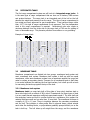
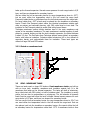


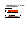
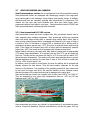
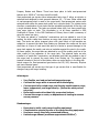

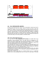


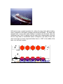


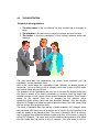


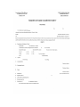


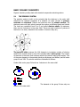


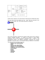

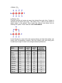
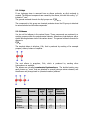
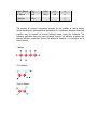
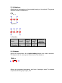


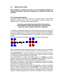


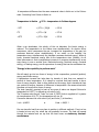

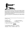


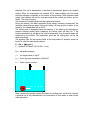


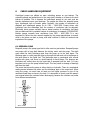

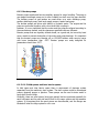


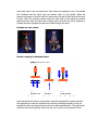
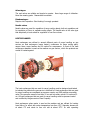


![Corel Office Document [PFP#241512617]](http://vs1.manualzilla.com/store/data/005699212_1-655f6a875c479857ca50d39f97eeaf8f-150x150.png)