1
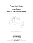
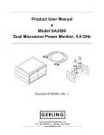
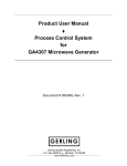
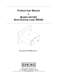
Product User Manual ♦ Model GA2604 Pressure/Vacuum Window, CPR159 Document # 930046, Rev. 1 GERLING Gerling Applied Engineering, Inc. P.O. Box 580816 ♦ Modesto, CA 95358 www.5800mhz.com Product User Manual Model GA2604 – Pressure/Vacuum Window, CPR159 REV. 1 REVISION HISTORY DESCRIPTION PROTOTYPE RELEASE Page 2 DATE 15JAN04 APPROVAL JFG WARRANTY Products manufactured and sold by Gerling Applied Engineering, Inc. (“GAE”) are warranted to be free of defects in materials and workmanship under normal use and service for a period of twelve (12) months from the date of original shipment. GAE’s obligation under this warranty is limited to repairing or replacing, at GAE’s option, all non-consumable component parts. Consumable parts are specifically excluded from this warranty and may include, but are not be limited to, magnetrons, fuses, lamps, seals, o-rings, v-belts, and fluids. All warranty repairs are to be done at GAE’s facility or as otherwise authorized by GAE. All shipping charges for warranty repair or replacement are the purchaser’s responsibility unless otherwise agreed to by GAE. This warranty supercedes all other warranties, expressed or implied. No warranty is given covering the product for any particular purpose other than as covered by the applicable product specifications. GAE assumes no liability in any event for incidental or consequential damages, financial losses, penalties or other losses incurred in conjunction with the use of GAE products. DOCUMENT CONVENTIONS NOTE: Means the reader should take note. Notes contain helpful information, suggestions, or references to other sections, chapters, or documents. CAUTION: Means the reader should be careful. You are doing something that might result in equipment damage or loss of data. WARNING: Means danger. A situation exists that could cause bodily injury or death. All personnel must be aware of the hazards involved with high voltage electrical circuitry and high power microwave devices. 2004 Gerling Applied Engineering, Inc. Modesto, CA Product User Manual Model GA2604 – Pressure/Vacuum Window, CPR159 Page 3 WARNING All waveguide components manufactured by GAE, Inc. are intended for use with other equipment capable of producing a microwave field that is potentially hazardous to operating personnel. They must never be connected or operated in a manner that allows a field in excess of 10 milliwatts per square centimeter to be generated in an area accessible to operating personnel. Contact GAE, Inc. for technical support prior to installation and/or operation of these units if there is any question or concern about microwave leakage. All waveguide flange and electrical cable connections throughout the system must be secure prior to operation. Never operate the microwave generator without a properly rated absorbing load attached. To ensure safe operation and prevent microwave leakage, the equipment must be periodically inspected and maintained as required or recommended. 2004 Gerling Applied Engineering, Inc. Modesto, CA Product User Manual Model GA2604 – Pressure/Vacuum Window, CPR159 Page 4 TABLE OF CONTENTS EQUIPMENT DESCRIPTION ......................................................................................... 5 General Specifications 5 INSTALLATION .............................................................................................................. 6 Preliminary Inspection Waveguide Configuration Flange Connections 6 6 7 OPERATION................................................................................................................... 8 Basic Operation Impedance Matching 8 8 MAINTENANCE............................................................................................................ 10 Window/O-Ring Replacement 2004 Gerling Applied Engineering, Inc. 10 Modesto, CA Product User Manual Model GA2604 – Pressure/Vacuum Window, CPR159 Page 5 EQUIPMENT DESCRIPTION Model GA2604 waveguide pressure/vacuum window delivers good performance at relatively high microwave power levels. A fused quartz silica window is captured between silicone o-rings in an aluminum base. Matching irises located on both sides ensure low VSWR across the ISM band. An additional o-ring is provide for external pressure/vacuum sealing to the mating flange surface. Optional materials are available for higher temperature operation, as well as alternate designs for liquid-cooling. General Specifications Frequency 5.8 GHz +/- 75 MHz Input Power 700 W continuous max. (into flat load) Waveguide WR159 (RG344/U) Waveguide Flange CPR159 (UG1731/U) Input VSWR 1.2 max. Insertion Loss .15 dB max Operating Temp -65 to +450 °F (-54 to +232 °C) Materials Aluminum base; Fused quartz window; Silicone o-rings Finish Chemical conversion coating 2004 Gerling Applied Engineering, Inc. Modesto, CA Product User Manual Model GA2604 – Pressure/Vacuum Window, CPR159 Page 6 INSTALLATION Preliminary Inspection Upon arrival at the installation site the GA2604 Pressure/Vacuum Window should be thoroughly inspected for damage or wear caused during shipping. Any visible damage to the packaging material or the applicator itself should be noted and reported immediately to the shipping company in accordance with standard claims procedures. The following components are included: a) GA2604 Pressure/Vacuum Window b) External o-ring c) Product User Manual (this document) Waveguide Configuration The GA2604 window can be connected to and used with any common waveguide component having a compatible flange (see below). Mounting can be in any convenient position and orientation with either flange positioned towards the microwave generator. The external o-ring should be located between the GA2604 and the device which is to be held under pressure or vacuum. Figure 1 illustrates a typical waveguide configuration. Figure 1. Typical waveguide configuration for process heating. Ideally, the GA2604 should be connected between components having the same characteristic impedance as standard WR159 waveguide. This will eliminate the need for a separate tuner or other impedance matching device for efficient power transmission through the GA2604. However, if a tuning device is required it should be located between the GA2604 and source of the 2004 Gerling Applied Engineering, Inc. Modesto, CA Product User Manual Model GA2604 – Pressure/Vacuum Window, CPR159 Page 7 impedance mismatch. See “Impedance Matching” in the next section for a more detailed discussion on this topic. Flange Connections Both flanges of the GA2604 must be properly connected to another waveguide component. Bolts must be installed at all flange bolt holes on both flanges and tightened securely prior to operation. Microwave Leakage – Regulatory limits for microwave leakage relate to standards for human safety and interference with other electronic devices. Standards for human safety as adopted by OSHA, the International Electrotechnical Commission (IEC) and other regulatory agencies limit leakage to 5 mW/cm2 measured at 5 cm from the leakage source under normal operating conditions, and 10 mW/cm2 at 5 cm from the source under abnormal operating conditions. The U.S. Federal Communications Commission (FCC) has established regulations limiting the emission of energy at frequencies outside the ISM bands. All GAE waveguide components meets these requirements when properly connected to another waveguide component. 2004 Gerling Applied Engineering, Inc. Modesto, CA Product User Manual Model GA2604 – Pressure/Vacuum Window, CPR159 Page 8 OPERATION Basic Operation Once installed, the GA2604 window will operate without any need for operator involvement. No adjustments or settings are available or necessary, except as may be required by the load adapter or other process requirements. Impedance Matching As discussed in the previous section, locating the GA2604 between components having the same characteristic impedance as standard WR159 waveguide will eliminate the need for a separate tuner or other impedance matching device to compensate for a mis-match of the downstream waveguide component. However, the process chamber and internal load often have a combined impedance different from that of WR159 waveguide, thus necessitating an impedance matching device to obtain efficient power coupling to the load. In such cases, the impedance matching device should be located between the GA2604 and process load if at all possible. A matching iris is an effective method to match the load impedance to waveguide, although it may be unsuitable if an adjustable impedance matching device such as a multi-stub tuner is required. However, most waveguide tuners are not capable of supporting pressure or vacuum inside the waveguide and must therefore be located on the non-pressurized side of the GA2604. If the GA2604 must be located between the tuner and load mismatch then certain considerations must be made and steps taken to ensure reliable and safe operation. The average electric field (e-field) strength between the tuning device and process load is a function of the “Q” (quality factor) of the load. Heating a high Q load results in higher average e-fields which in turn cause higher power dissipation wherever the e-fields are present. Locating the GA2604 where high e-fields are present can cause excessive power dissipation in the window and o-ring materials. The resulting high temperatures can cause burning and eventual failure of the o-rings, thus loosing their capability to support a pressure or vacuum. Locating the GA2604 between the tuner and load does not necessarily result in overheating and premature failure. For example, many process loads have a low Q and low impedance mismatch, thus resulting in only a moderate increase in e-field upon tuning. Similarly, heating a high Q load at low power levels may 2004 Gerling Applied Engineering, Inc. Modesto, CA Product User Manual Model GA2604 – Pressure/Vacuum Window, CPR159 Page 9 result in moderately high e-fields and minimal dissipation into the window and o-ring materials. In any case, the user should be aware of the circumstances and conditions under which the GA2604 will be used and exercise caution when operating under high Q and high power conditions. 2004 Gerling Applied Engineering, Inc. Modesto, CA Product User Manual Model GA2604 – Pressure/Vacuum Window, CPR159 Page 10 MAINTENANCE The GA2604 Pressure/Vacuum Window is designed to be maintenance free under normal operating conditions and does not require any user maintenance. No calibration is necessary. However, the o-rings supplied with the GA2604 may be subject to overheating and damage during operation under high electric field conditions (see previous discussion in previous section). In the event of damage to the window or o-rings, replacements may be obtained from GAE by ordering one of the following: Part Number Description 911366 420101-225 420103-225 Window, Fused Quartz O-Ring, Silicone (232 °C max.) O-Ring, Perfluoroelastomer (300 °C max.) Window/O-Ring Replacement Figure 2 below is an exploded view of the GA2604 assembly. Replacement of the window and/or o-rings involves simply removing the six socket head screws (and lockwashers) and separation of the two base pieces. Upon removing the window and o-rings, carefully clean the o-ring seats of any residue that may have collected. Clean the window of all grease and residue prior to reassembly. Tighten the screws evenly on one side only until secure before proceeding to install the screws on the other side. Figure 2. Exploded view of the GA2604 window assembly. 2004 Gerling Applied Engineering, Inc. Modesto, CA