1
Product User Manual
♦
Process Control System
for
GA4307 Microwave Generator
Document # 930048, Rev. 1
GERLING
Gerling Applied Engineering, Inc.
P.O. Box 580816 ♦ Modesto, CA 95358
www.5800mhz.com
Product User Manual
Process Control System for GA4307 Microwave Generator
REV.
1
REVISION HISTORY
DESCRIPTION
PROTOTYPE RELEASE
Page 2
DATE
27MAR04
APPROVAL
JFG
WARRANTY
Products manufactured and sold by Gerling Applied Engineering, Inc. (“GAE”) are
warranted to be free of defects in materials and workmanship under normal use and
service for a period of twelve (12) months from the date of original shipment. GAE’s
obligation under this warranty is limited to repairing or replacing, at GAE’s option, all
non-consumable component parts. Consumable parts are specifically excluded from
this warranty and may include, but are not be limited to, magnetrons, fuses, lamps,
seals, o-rings, v-belts, and fluids. All warranty repairs are to be done at GAE’s facility or
as otherwise authorized by GAE. All shipping charges for warranty repair or
replacement are the purchaser’s responsibility unless otherwise agreed to by GAE.
This warranty supercedes all other warranties, expressed or implied. No warranty is
given covering the product for any particular purpose other than as covered by the
applicable product specifications. GAE assumes no liability in any event for incidental or
consequential damages, financial losses, penalties or other losses incurred in
conjunction with the use of GAE products.
DOCUMENT CONVENTIONS
NOTE: Means the reader should take note.
Notes contain
helpful information, suggestions, or references to other sections,
chapters, or documents.
CAUTION: Means the reader should be careful.
You are doing
something that might result in equipment damage or loss of data.
WARNING: Means danger. A situation exists that could cause
bodily injury or death. All personnel must be aware of the hazards
involved with high voltage electrical circuitry and high power
microwave devices.
2004 Gerling Applied Engineering, Inc.
Modesto, CA
Product User Manual
Process Control System for GA4307 Microwave Generator
Page 3
WARNING
All microwave generators manufactured by GAE, Inc. are capable of producing a
microwave field that is potentially hazardous to operating personnel. They must never
be connected or operated in a manner that allows a field in excess of 10 milliwatts per
square centimeter to be generated in an area accessible to operating personnel.
Contact GAE, Inc. for technical support prior to installation and/or operation of these
units if there is any question or concern about microwave leakage.
All waveguide flange and electrical cable connections throughout the system must be
secure prior to operation. Never operate the microwave generator without a properly
rated absorbing load attached. To ensure safe operation and prevent microwave
leakage, the equipment must be periodically inspected and maintained as required or
recommended.
2004 Gerling Applied Engineering, Inc.
Modesto, CA
Product User Manual
Process Control System for GA4307 Microwave Generator
Page 4
TABLE OF CONTENTS
LIST OF FIGURES.......................................................................................................... 5
EQUIPMENT DESCRIPTION ......................................................................................... 6
General Specifications
Components Supplied
6
7
INSTALLATION .............................................................................................................. 8
Preliminary Inspection
Module Installation
Interconnect Cables
Line Power Connection
Control Wiring Connections
Thermocouple Connection
8
8
8
9
9
9
BASIC OPERATION..................................................................................................... 10
Start-up and Shut-down
10
CONTROL SOFTWARE ............................................................................................... 12
Basic Software Functions
Launching the Program
Logon Screen
Data File Set-Up Screen
Data Collection Screen
Recalling Previous Data
12
12
13
17
20
24
MAINTENANCE AND CALIBRATION ......................................................................... 27
2004 Gerling Applied Engineering, Inc.
Modesto, CA
Product User Manual
Process Control System for GA4307 Microwave Generator
Page 5
LIST OF FIGURES
Figure 1. Block diagram of the Process Control System. ................................................ 8
Figure 2. Wiring connections between the SCCB and GA4307 microwave generator. ... 9
Figure 3. Windows desktop showing the PCS software icon......................................... 12
Figure 4. The logon screen. .......................................................................................... 13
Figure 5. Pressing [OK] on this screen will return you to the Main screen. ................... 14
Figure 6. Pressing [OK] on this screen will return you to the Main screen. ................... 14
Figure 7. Main screen after entry of valid operator name and password....................... 15
Figure 8. Configuration screen after entry of valid supervisor name and password. ..... 16
Figure 9. Set-Up screen entry of the unique data file name. ......................................... 17
Figure 10. Set-up screen: File name more than 12 digits warning. ............................... 18
Figure 11. Set-up screen: Duplicate file name decision. ............................................... 18
Figure 12. Set-up screen: Enter another new file name. ............................................... 18
Figure 13. Set-up screen: File transaction concatenated message............................... 19
Figure 14. Set-up screen after the unique file name has been successfully entered. ... 19
Figure 15. Data collection screen.................................................................................. 21
Figure 16. Data Collection Screen after the PID loop screen has been selected. ......... 22
Figure 17. Data Collection Screen with the PID loop tuning screen displayed. ............. 22
Figure 18. Data Collection Screen with statistics displayed. ......................................... 23
Figure 19. Data file set-up screen. ................................................................................ 24
Figure 20. Set-up screen for selecting existing data file. ............................................... 25
Figure 21. Duplicate File Name Detected dialog box. ................................................... 25
Figure 22. Change File Name dialog box. ..................................................................... 25
Figure 23. Exit Program Critical Error dialog box. ......................................................... 25
2004 Gerling Applied Engineering, Inc.
Modesto, CA
Product User Manual
Process Control System for GA4307 Microwave Generator
Page 6
EQUIPMENT DESCRIPTION
The Process Control System (PCS) described in this manual is
designed for use with the GA4307 microwave generator for simple
PID control of process temperature. The PCS reads an analog
input signal from a thermocouple sensor that detects the
temperature of a material being heated by microwave energy
generated by the GA4307 and controls the output power level of
the GA4307 by means of an analog output voltage signal.
The PCS is a laptop computer based system with National
Instruments peripheral hardware and customized PID control
software. Functional controls provided in the software include
microwave start/stop buttons, user adjustment of the temperature
control setpoint, and user-adjustable PID loop parameters to
provided flexibility in fine-tuning specific processes. A detailed
explanation of the control software is provided in a separate
instruction manual accompanying this document.
General Specifications
Computer
I/O Interface
Software
Analog Input
Analog Output
Digital Output
Controls
Line Power
Connectors
2004 Gerling Applied Engineering, Inc.
Dell Latitude D600 Laptop with MSWindows XP
National Instruments DAQCard-6023E
Custom PID control software
Type K thermocouple
0-10 VDC
Two dry contact relays wired NO and
NC
Mw Start (NO relay contact)
Mw Stop (NC relay contact)
Process temperature setpoint
PID loop parameters
100-240 VAC, 50/60 Hz, 2.5 Amps
9-pin male D-sub
Modesto, CA
Product User Manual
Process Control System for GA4307 Microwave Generator
Components Supplied
Item Description
Mfr
Page 7
Part Number
Computer
Dell
Latitude D600
(includes power supply and mouse)
I/O Interface
National Inst.
Signal Conditioning
Connector Block
National Inst.
SC-2345
(includes power supply)
Analog Input Module
National Inst.
SCC-TC02
Analog Output Module
National Inst.
SCC-AO10
Digital Output Module
National Inst.
SCC-RLY01 (2 ea.)
Interconnect Cable
National Inst.
1868386-01
Product User Manual
GAE
930048
(this document)
2004 Gerling Applied Engineering, Inc.
DAQCard-6023E
Modesto, CA
Product User Manual
Process Control System for GA4307 Microwave Generator
Page 8
INSTALLATION
Preliminary Inspection
Upon arrival at the installation site the PCS system components
should be thoroughly inspected for damage or wear caused during
shipping. Any visible damage to the packaging material or the
equipment itself should be noted and reported immediately to the
shipping company in accordance with standard claims procedures.
Module Installation
The PCS is intended for use in a clean dry environment, such as a
laboratory or cleanroom, or anywhere a typical laptop computer can
be used. The individual system components can be installed in any
orientation that is convenient for connection to the magnetron head
and a source of line power.
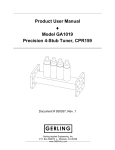
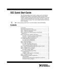
Interconnect Cables
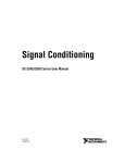
All cables required for interconnection between PCS system
components and the magnetron head are provided. Figure 1 is a
block diagram of the PCS illustrating the component
interconnections.
Figure 1. Block diagram of the Process Control System.
2004 Gerling Applied Engineering, Inc.
Modesto, CA
Product User Manual
Process Control System for GA4307 Microwave Generator
Page 9
Line Power Connection
Line power connections to standard three-prong 115 VAC outlet
receptacles are required for the Signal Conditioning Connector
Block (SCCB) and Laptop Computer as shown in Figure 1.
Grounded receptacles must be used for regulatory safety
compliance.
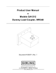
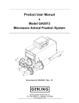
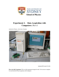
Control Wiring Connections
Figure 2 below illustrates the wiring connections between the PCS
and GA4307 microwave generator (magnetron head). A wiring
harness with the 9-pin D-sub connector is provided with the PCS.
Figure 2. Wiring connections between the SCCB and GA4307
microwave generator.
Thermocouple Connection
Figure 2 above shows connection of a customer-supplied Type K
thermocouple to the T/C input module located at position J1 in the
SCCB.
NOTE: Other thermocouple types may also be used. However,
this requires a change to the hardware set-up configuration. See
the NI-DAQ user manual(s) for more information on changing the
hardware set-up parameters.
2004 Gerling Applied Engineering, Inc.
Modesto, CA
Product User Manual
Process Control System for GA4307 Microwave Generator
Page 10
BASIC OPERATION
The PCS operates the microwave generator by a) providing basic
manually operated on-off control of microwave power, b) automatic
PID control of the microwave output power level to maintain a
process setpoint temperature, and c) manual control of microwave
output power while bypassing the PID control loop. All control
functionality is accessed within a customized software environment
on a laptop computer.
Start-up and Shut-down
The following basic procedure may be used as a guideline for startup and shut-down of the PCS. Alterations to this procedure may be
necessary to accommodate standard shop/lab procedures and/or
other operational requirements.
1. Connect the PCS and microwave generator to their
respective sources of line power.
NOTE: The SCCB does not have a power switch. It will be
operational upon connecting line power.
2. Turn on the microwave generator by actuating the main
power switch located on the side of the power supply.
3. Set the toggle switch located on the magnetron head front
panel to “Remote” to allow the PCS to control the microwave
output power level.
4. Turn on the laptop computer by pressing the power button
below the display screen. Log into MS-Windows® and allow
the computer to reach a steady state of operation.
5. Turn on the PCS software application as follows:
a. Double-click the “GAE” icon located on the MSWindows® desktop.
b. Refer to the next section for detailed instructions on
software operation and system control.
6. Any of the following actions will safety stop the PCS from
operating without causing damage to the system:
a. Click EXIT to terminate PCS software operation.
b. Turn off the laptop computer.
c. Unplug the SC-2345 Signal Conditioning Chassis.
Note that this action will not stop the PCS software
application from operating.
2004 Gerling Applied Engineering, Inc.
Modesto, CA
Product User Manual
Process Control System for GA4307 Microwave Generator
Page 11
WARNING: Stopping the PCS from operating will not
necessarily stop microwave power from being generated. See
below for information and procedures to safely turn off microwave
power.
7. Microwave power can be turned off by any of the following
operations:
a. Click the MICROWAVE POWER ON – PRESS TO
TURN MICROWAVE OFF button on the PCS main
data collection screen.
b. Press the MW STOP button on the front panel of the
magnetron head.
c. Disconnect line power from the GA4307 microwave
generator.
2004 Gerling Applied Engineering, Inc.
Modesto, CA
Product User Manual
Process Control System for GA4307 Microwave Generator
Page 12
CONTROL SOFTWARE
The PCS software program is specifically designed for use with the
model GA4307 microwave generator and custom process control
system. The program utilizes internal databases and communicates
with the SCC family of hardware modules manufactured by
National Instruments to form an integrated system that
automatically controls the microwave power according to the
temperature set point.
Basic Software Functions
The PC coordinates the activity of all the components in the overall
system using the following control functions:
A unique data collection file is created each time the
program is started.
The operator can start and stop the data collection and
microwave generator.
The program displays and records each new sampled data
point for display and archiving.
The temperature control response can be fine tuned by
adjusting the PID control parameters.
Previous data files can be recalled and displayed.
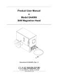
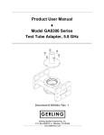
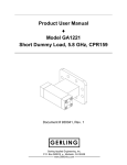
Launching the Program
The software program is launched by selecting the “GAE” icon from
the main desktop screen as shown below.
Figure 3. Windows desktop showing the PCS software icon.
2004 Gerling Applied Engineering, Inc.
Modesto, CA
Product User Manual
Process Control System for GA4307 Microwave Generator
Page 13
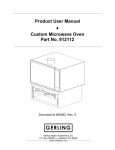
Logon Screen
The logon screen appears after the program finishes loading. To
progress from this screen, a correct security operator identification
and associated password must be entered.
The logon screen:
Provides access to the system, program engineering, and/or
configuration screens if an engineering level identification
and associated password are entered.
Allows normal operation access to the program if any correct
operator identification and associated password are entered.
Figure 4. The logon screen.
2004 Gerling Applied Engineering, Inc.
Modesto, CA
Product User Manual
Process Control System for GA4307 Microwave Generator
Page 14
Logon Screen Invalid Operator Entry
The operator or supervisor must enter a valid name and password
in order to operate the program. Valid identification names are
configured using the “Engineering and Configuration” screen (see
next section). Valid operator names must be set-up by a supervisor
who has been granted access to the system configuration screens.
If an invalid operator name is entered, an “Invalid Operator” entry
pop-up screen will be displayed.
Figure 5. Pressing [OK] on this screen will return you to the Main
screen.
NOTE: Operator Identification entries are case sensitive and
must match one of the configured operator names.
Logon Screen Invalid Password Entry
Each valid operator, supervisor, or engineer name has an
associated password that must be entered in order to operate the
program. Valid operator identification passwords are configured
from the “Engineering and Configuration” screen. An engineer who
has access to the system configuration screens must set up
operator passwords.
If an invalid operator name is entered, a pop-up screen will be
displayed to warn that an incorrect name has been entered.
Figure 6. Pressing [OK] on this screen will return you to the Main
screen.
NOTE: Password entries are case sensitive and must match one
of the configured operator passwords.
2004 Gerling Applied Engineering, Inc.
Modesto, CA
Product User Manual
Process Control System for GA4307 Microwave Generator
Page 15
Logon Screen Operator Level Identification and Password
After entering a valid operator name and password (default values
are “AAA” and “12345”), a button below the password entry area
becomes active. The entry fields will become green to indicate that
the security level is set for operator control only.
Figure 7. Main screen after entry of valid operator name and
password.
2004 Gerling Applied Engineering, Inc.
Modesto, CA
Product User Manual
Process Control System for GA4307 Microwave Generator
Page 16
Main Screen Supervisor Level Identification and Password
After entering a valid supervisor level name and password (default
values are “GAE” and “GAE”), a button below the password entry
area becomes active. Double-clicking this button will open the
Configuration Set Up Screen.
Figure 8. Configuration screen after entry of valid supervisor name
and password.
Most of the information displayed in the Configuration screen is
provided for non-user and/or optional program functionality. The
primary task allowed for the is the entry and editing of operator
usernames and passwords.
Operator ID – Any alpha-numeric value (case-sensitive)
Operator Password – Any alpha-numeric value (case-sensitive)
Security Level – Use “1” for all operators and “99” for all
supervisors.
Exiting the Program from the Logon Screen
An operator has the option to exit the program from the main
screen by selecting the “Exit” button from the menu selector located
in the upper left corner of the screen.
2004 Gerling Applied Engineering, Inc.
Modesto, CA
Product User Manual
Process Control System for GA4307 Microwave Generator
Page 17
Data File Set-Up Screen
Set-Up Screen File Selection
The screen will appear and will contain a data file name entry box
where a unique file name must be entered. After the desired
transaction file name has been entered, the <TAB> button must be
pressed to accept the entry. The file name entered must be unique
and less than 12 characters long. No file name extension (i.e. .doc,
.txt) is required. If the file name already exists, it can be optionally
concatenated with {_1 through _99} if desired by the operator. The
operator should choose names that will be easy to identify and
have some meaning—for example:
sampledata_1a
ENTER A UNIQUE FILE NAME
Figure 9. Set-Up screen entry of the unique data file name.
2004 Gerling Applied Engineering, Inc.
Modesto, CA
Product User Manual
Process Control System for GA4307 Microwave Generator
Page 18
Set-Up Screen – Check the File Name
The file name is checked to insure that it is no longer then 12
characters long. If the file name exceeds 12 characters, an error
box will appear advising that the file name has been automatically
truncated to 12 digits.
Figure 10. Set-up screen: File name more than 12 digits warning.
The file name must be unique and each transaction file that is
entered will be checked against all of the other file names in the
directory to ensure that no duplicate file exists. If a duplicate file is
detected, a warning pop-up message will give the operator the
opportunity to enter another new and unique transaction file name.
Figure 11. Set-up screen: Duplicate file name decision.
If the “Yes” from Figure 11 is selected then the original entry file
pop-up screen appears and a unique file name should be entered.
Figure 12. Set-up screen: Enter another new file name.
If the “No” from Figure 11 is selected, then the file name entered
will be concatenated with a sequential suffix to automatically create
a unique file name.
2004 Gerling Applied Engineering, Inc.
Modesto, CA
Product User Manual
Process Control System for GA4307 Microwave Generator
Page 19
Figure 13. Set-up screen: File transaction concatenated message.
SELECTED DIRECTORY PATH AND
UNIQUE TRANSACTION FILE NAME
Figure 14. Set-up screen after the unique file name has been
successfully entered.
After pressing the “Begin Data Collection” button the Data
Collection screen will appear.
2004 Gerling Applied Engineering, Inc.
Modesto, CA
Product User Manual
Process Control System for GA4307 Microwave Generator
Page 20
Data Collection Screen
After the set-up is complete and a unique file name has been
entered, the Data Collection screen (Figure 15) will be displayed.
The Data Collection screen will remain visible until the program is
shut down or another data collection file is selected.
Main Data Indicators
The Data Collection screen has the displays and status indicators
necessary to monitor all aspects of the microwave control and data
collection system.
Digital indicators will continuously display the set point,
current temperature, error from set point and the current
elapsed time.
The control mode “Manual” or “Auto” will show with a green
or red background color indictor.
The microwave generator “On” or “Off” will show with a
green or red background color indictor.
The chart located below the display indicators shows a realtime record of either current temperature or temperature
error throughout the process cycle.
The TEMPERATURE DATA COLLECTION HISTORY grid located
below the indicator panels will display the data collection
processing history. Selecting the any of the column table header
row will automatically sort the complete database in ascending
order using based on the column selected.
The output control voltage and input temperature signals along with
the current setpoint value can be shown in a slider type display
(Figure 16) by clicking the PID LOOP DISPLAY button located in
the upper left corner.
Basic Operator Controls
Located above the display indicators are buttons for manually
turning on and off the microwave generator and data collection.
The microwave generator can be started by clicking on the red
MICROWAVE POWER OFF – PRESS TO TURN
MICROWAVE ON button. This button will then change to green
and read MICROWAVE POWER ON – PRESS TO TURN
MICROWAVE OFF. Microwave power can be toggled on and
off by simply clicking this button.
Data collection can be started or stopped by clicking on the
DATA COLLECT button. This button will be red and read OFF
when data collection is off, and it will be green and read ON
when data is being collected.
2004 Gerling Applied Engineering, Inc.
Modesto, CA
Product User Manual
Process Control System for GA4307 Microwave Generator
Page 21
The screen can be exited by clicking on the NEW LOG FILE
SET-UP button located on the upper right corner of the screen.
After selecting the button, the Set-up screen will be displayed
again.
The program can be exited by clicking the EXIT button in the
upper left corner of the screen.
Figure 15. Data collection screen.
Automatic and Manual Control Modes
While the PID LOOP DISPLAY is showing, the operator can
monitor the status of the input and output signals and overall
controller performance. Upon initially turning on microwave power,
the PID loop will be in “automatic” mode which controls the output
signal according the PID loop parameter settings and relationship
between the temperature signal and setpoint value. This mode will
be indicated in two ways:
The AUTO MODE radio button will be green and the MANUAL
MODE button will be red, and
The bar just below the digital value indicators will be green and
read PID LOOP – AUTOMATIC MODE.
Clicking on the PID LOOP – AUTOMATIC MODE bar (Figure 16)
will change the controls to “manual” mode as indicated by the
AUTO and MANUAL radio buttons will reverse colors and bar will
change to blue and read PID LOOP – MANUAL MODE. In this
2004 Gerling Applied Engineering, Inc.
Modesto, CA
Product User Manual
Process Control System for GA4307 Microwave Generator
Page 22
mode the operator can manually adjust microwave output power by
sliding (left-click and hold) the OUTPUT slider indicator up or down.
CLICK AND HOLD POINTER AND SLIDE UP
OR DOWN TO ADJUST MICROWAVE
POWER IN MANUAL MODE
SELECT TO CHANGE THE PID LOOP
MANUAL OR AUTO MODE
Figure 16. Data Collection Screen after the PID loop screen has
been selected.
SELECT TO CHANGE THE PID LOOP
TUNING PARAMETERS
Figure 17. Data Collection Screen with the PID loop tuning screen
displayed.
2004 Gerling Applied Engineering, Inc.
Modesto, CA
Product User Manual
Process Control System for GA4307 Microwave Generator
Page 23
PID Loop Parameters
Clicking on the LOOP TUNING PARAMETERS bar (Figure 17)
displays the PID loop parameter controls and indicators. Adjust
each parameter by moving (left-click and hold) the respective slider
while observing the indicated value.
Data Statistics
Clicking anywhere on the chart will display the statistical values for
the data being collected (Figure 18). Move the vertical red line to
the position on the chart for display of specific data values.
SELECT GRID TO VIEW STATISTICS
MOVE RED LINE TO VIEW
SPECIFIC SAMPLED DATA
Figure 18. Data Collection Screen with statistics displayed.
2004 Gerling Applied Engineering, Inc.
Modesto, CA
Product User Manual
Process Control System for GA4307 Microwave Generator
Page 24
Recalling Previous Data
The data collected during previous sessions can be displayed on
the Data Collection Screen. Use the following procedure to recall
an existing data file.
1. To open an existing data file, click the DIRECTORY FILE
SELECTOR bar in the data file selection screen (Figure 19).
CLICK ON HEADER TO RECALL DATA FILES
Figure 19. Data file set-up screen.
2. The file directory (folder) where data files are stored will
appear (Figure 20. Select the desired file by double-clicking
on the file name.
3. The selected file will then be displayed in File Selection
Screen (Figure 19). Click on the CLICK TO BEGIN DATA
COLLECTION bar.
4. The Duplicate File Name dialog box will then appear (Figure
21). Select “No” to indicate that you want to use the name
shown.
5. The Change File Name dialog box (Figure 22) will then
appear. Select “No” again to indicate that you wish to display
the existing file information.
6. If the Exit Program Critical Error dialog box appears (Figure
23), ignore it by clicking either “OK” or “Cancel”.
2004 Gerling Applied Engineering, Inc.
Modesto, CA
Product User Manual
Process Control System for GA4307 Microwave Generator
Page 25
DOUBLE-CLICK DESIRED FILE TO DISPLAY
Figure 20. Set-up screen for selecting existing data file.
Figure 21. Duplicate File Name Detected dialog box.
Figure 22. Change File Name dialog box.
Figure 23. Exit Program Critical Error dialog box to be ignored.
2004 Gerling Applied Engineering, Inc.
Modesto, CA
Product User Manual
Process Control System for GA4307 Microwave Generator
Page 26
The entire history of the recalled data will now be displayed in the
Data Collection Screen. Note that the control buttons will appear to
be active as they will change color and message clicked. However,
the control functionality of these buttons has been disabled while
viewing existing data files.
To exit the program from this screen, click the normal Windows
“Close” button in the upper right corner of the window.
2004 Gerling Applied Engineering, Inc.
Modesto, CA
Product User Manual
Process Control System for GA4307 Microwave Generator
Page 27
MAINTENANCE AND CALIBRATION
The Process Control System (PCS) is designed to be maintenance
free and does not contain any consumable components. No
calibration is necessary except for that of the thermocouples
provided by the customer and used with the PCS.
However, the PCS can be subject to damage due to improper
operating conditions or mishandling. If damage occurs, the system
should be returned to GAE for repair. Contact GAE for information
on repair services.
2004 Gerling Applied Engineering, Inc.
Modesto, CA