1
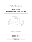
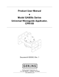
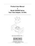
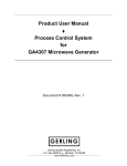
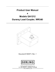
Product User Manual ♦ Model GA1221 Short Dummy Load, 5.8 GHz, CPR159 Document # 930041, Rev. 1 GERLING Gerling Applied Engineering, Inc. P.O. Box 580816 ♦ Modesto, CA 95358 www.5800mhz.com Product User Manual Model GA1221 – Short Dummy Load, 5.8 GHz, CPR159 REV. 1 REVISION HISTORY DESCRIPTION PROTOTYPE RELEASE Page 2 DATE 15JAN04 APPROVAL JFG WARRANTY Products manufactured and sold by Gerling Applied Engineering, Inc. (“GAE”) are warranted to be free of defects in materials and workmanship under normal use and service for a period of twelve (12) months from the date of original shipment. GAE’s obligation under this warranty is limited to repairing or replacing, at GAE’s option, all non-consumable component parts. Consumable parts are specifically excluded from this warranty and may include, but are not be limited to, magnetrons, fuses, lamps, seals, o-rings, v-belts, and fluids. All warranty repairs are to be done at GAE’s facility or as otherwise authorized by GAE. All shipping charges for warranty repair or replacement are the purchaser’s responsibility unless otherwise agreed to by GAE. This warranty supercedes all other warranties, expressed or implied. No warranty is given covering the product for any particular purpose other than as covered by the applicable product specifications. GAE assumes no liability in any event for incidental or consequential damages, financial losses, penalties or other losses incurred in conjunction with the use of GAE products. DOCUMENT CONVENTIONS NOTE: Means the reader should take note. Notes contain helpful information, suggestions, or references to other sections, chapters, or documents. CAUTION: Means the reader should be careful. You are doing something that might result in equipment damage or loss of data. WARNING: Means danger. A situation exists that could cause bodily injury or death. All personnel must be aware of the hazards involved with high voltage electrical circuitry and high power microwave devices. 2004 Gerling Applied Engineering, Inc. Modesto, CA Product User Manual Model GA1221 – Short Dummy Load, 5.8 GHz, CPR159 Page 3 WARNING All waveguide dummy loads manufactured by GAE are intended for use with other equipment capable of producing a microwave field that is potentially hazardous to operating personnel. It must never be connected or operated in a manner that allows a field in excess of 10 milliwatts per square centimeter to be generated in an area accessible to operating personnel. Contact GAE, Inc. for technical support prior to installation and/or operation of this unit if there is any question or concern about microwave leakage. All waveguide flange and electrical cable connections throughout the system must be secure prior to operation. Never operate the microwave generator without a properly rated absorbing load attached. To ensure safe operation and prevent microwave leakage, the equipment must be periodically inspected and maintained as required or recommended. 2004 Gerling Applied Engineering, Inc. Modesto, CA Product User Manual Model GA1221 – Short Dummy Load, 5.8 GHz, CPR159 Page 4 TABLE OF CONTENTS EQUIPMENT DESCRIPTION ......................................................................................... 5 Specifications 5 INSTALLATION .............................................................................................................. 6 Preliminary Inspection Waveguide Configuration Flange Connections Water Flow Requirements Water Fitting Connections Storage and Shipping 6 6 6 7 8 8 THEORY OF OPERATION ............................................................................................. 9 Basic Operation Performance Considerations 9 9 USER MAINTENANCE AND REPAIR.......................................................................... 10 Quartz Tube Replacement Procedure 2004 Gerling Applied Engineering, Inc. 10 Modesto, CA Product User Manual Model GA1221 – Short Dummy Load, 5.8 GHz, CPR159 Page 5 EQUIPMENT DESCRIPTION The GA1221 Short Dummy Load is designed for use in high power microwave networks as a means to dissipate up to 700 Watts of microwave power at 5.8 GHz. The compact design and high reliability of this load makes it ideal for a variety of uses. Typical applications include magnetron isolation from reflected power (when used with a 3-port circulator), high power test stations and variable Q applicators. As with all GAE dummy loads, model GA1221 uses ordinary water as the absorptive medium. With quartz tubing for water conveyance, the internal geometry was computer-optimized to maximize return loss over a broad range of operating temperatures. Stainless steel water connections minimize corrosion from harsh water supplies to further enhance reliability and life. The waveguide body is fabricated with dip brazed aluminum. Specifications Frequency Input Power Waveguide Input Flange Return Loss Coupling Factor Water Connections Water Flow 5.8 GHz +/- 75 MHz 3 kW continuous max. WR159 (RG344/U) CPR159F (UG1731/U) 20 dB min. (inlet/outlet water temp within 20-50°C) 60 dB +/- 0.2 dB (GA1222 only) 1/8 NPT Female 0.5 gpm nominal Water Temp Inlet: 50 °F (10 °C) minimum Outlet: 140 °F (60 °C) maximum Water Pressure Construction 70 psig max. inlet Aluminum waveguide, stainless steel water connections Chemical conversion coating; textured black paint Finish 2004 Gerling Applied Engineering, Inc. Modesto, CA Product User Manual Model GA1221 – Short Dummy Load, 5.8 GHz, CPR159 Page 6 INSTALLATION Preliminary Inspection Upon arrival at the installation site the dummy load should be thoroughly inspected for damage or wear caused during shipping. Any visible damage to the packaging material or dummy load should be noted and reported immediately to the shipping company in accordance with standard claims procedures. The following components are included: a) Short Dummy Load b) Product User Manual Waveguide Configuration The dummy load can be connected to and used with any common waveguide component having a compatible flange. The mounting position can be in any orientation. Figure 1 below illustrates a common configuration in which the dummy load is used in conjunction with a 3-port circulator to protect the magnetron by absorbing microwave power reflected from the process load. Figure 1. Typical waveguide configuration using the dummy load to absorb reflected microwave power. Flange Connections The waveguide flange of the dummy load must be properly connected to another waveguide component having a similar flange style. All flange bolts must be installed and properly tightened to ensure a secure connection. 2004 Gerling Applied Engineering, Inc. Modesto, CA Product User Manual Model GA1221 – Short Dummy Load, 5.8 GHz, CPR159 Page 7 Microwave Leakage – Regulatory limits for microwave leakage relate to standards for human safety and interference with other electronic devices. Standards for human safety as adopted by OSHA, the International Electrotechnical Commission (IEC) and other regulatory agencies limit leakage to 5 mW/cm2 measured at 5 cm from the leakage source under normal operating conditions, and 10 mW/cm2 at 5 cm from the source under abnormal operating conditions. The U.S. Federal Communications Commission (FCC) has established regulations limiting the emission of energy at frequencies outside the ISM bands. All GAE waveguide components meets these requirements when properly connected to another waveguide component. Water Flow Requirements A source of water must be connected to the dummy load that provides an adequate rate of flow. The nominal water flow rate is 0.5 gpm. However, the flow rate must be maintained such that the outlet water temperature does not exceed 140 °F. The minimum allowable flow rate depends on the level of incident microwave power and the inlet water temperature. Figure 2 below shows the minimum flow rate vs. incident microwave power and inlet water temperature. Minimum Flow Rate (gpm) 0.60 700 W 0.50 500 W 0.40 300 W 100 W 0.30 0.20 0.10 0.00 40 60 80 100 120 140 Inlet Water Temp (F) Figure 2. Recommended minimum water flow rates for given inlet water temperature and incident microwave power level. CAUTION: Failure to provide an adequate rate of water flow can result in severe damage to the dummy load. It is strongly recommended that an interlock device such as an in-line water flow switch be used to prevent operation of the microwave generator in the event of inadequate or loss of water flow. 2004 Gerling Applied Engineering, Inc. Modesto, CA Product User Manual Model GA1221 – Short Dummy Load, 5.8 GHz, CPR159 Page 8 NOTE: Reduced performance can result if the tube is not completely filled with water. Upon initial installation and start-up of the dummy load and water circulation system, extremely low water flow rates can be insufficient to purge the internal quartz tube of air bubbles. Complete air purging can be ensured by a) a high rate of water flow upon initial start-up, and/or b) tilting the dummy load from side to side to allow trapped air to escape. Once all air is purged from the quartz tube, the water flow rate may be reduced within guidelines provided elsewhere in this manual. Water Fitting Connections Standard 1/8 NPT female fittings are provided at the end of the dummy load opposite the waveguide flange. The source of water can be connected to either fitting. It is recommended that a thread sealant such as Teflon pipe thread tape be used to ensure a leakfree connection. Care should be taken to prevent debris from falling into the fitting holes. Storage and Shipping Upon removing the dummy load from the set-up it is recommended that all water be drained prior to storage or shipping. This precaution will prevent damage in the event that freezing temperatures are encountered during storage or shipping. 2004 Gerling Applied Engineering, Inc. Modesto, CA Product User Manual Model GA1221 – Short Dummy Load, 5.8 GHz, CPR159 Page 9 THEORY OF OPERATION Basic Operation The GA1221 dummy load utilizes water as the medium for absorbing microwave energy that enters through the waveguide flange. The internal quartz tube through which the water flows is transparent to microwave energy (referred to as having “low dielectric loss” characteristics) and allows the energy to be absorbed directly into the water. The dielectric loss of water is relatively high and is capable of absorbing over 99% of the incident microwave energy. Performance Considerations In order to absorb substantially all of the incident microwave energy, the characteristic impedance of the dummy load must be a close match to that of the waveguide to which it is connected. The factors that influence this impedance match include the microwave frequency, the dielectric properties of water, and the physical internal geometry of the waveguide and tube through which the water flows. The dielectric properties of most materials vary with changes in temperature. In the case of water, an increase in temperature causes a decrease in its dielectric loss and, in general, results in a decrease in microwave energy absorption. However, the geometry of the absorbing load can be optimized, or “tuned”, for the dielectric properties at a desired temperature. In this case, energy absorption is maximized at the design temperature and is reduced at both higher and lower temperatures. Computer optimization techniques were employed in designing the GA1221 for average water temperatures between 86 °F (30 °C) and 104 °F (40 °C), although good performance is exhibited for average temperatures within 68 °F (20 °C) and 122 °F (50 °C). For best performance the outlet water temperature should remain as close as possible to the inlet temperature. A low water flow rate and high incident power causes a large increase in temperature which, since the heated water is still inside the load, results in a “detuning” of the load impedance and a decrease in energy absorption. 2004 Gerling Applied Engineering, Inc. Modesto, CA Product User Manual Model GA1221 – Short Dummy Load, 5.8 GHz, CPR159 Page 10 USER MAINTENANCE AND REPAIR The GA1221 dummy load is designed to be maintenance free and do not require any user maintenance under normal operating conditions. However, the dummy loads can sustain damage if the water flow rate is insufficient to prevent vaporization (boiling) while operating under conditions of high incident microwave power. In the event of damage due to insufficient or lack of water flow, the dummy load can be easily repaired by replacing the internal quartz tube. Repair kit model GA8106 available from GAE includes all necessary components for replacement of the quartz tube. Quartz Tube Replacement Procedure 1.1 Equipment Requirements Hex (Allen) driver, 7/64” 1.2 Disassembly WARNING: Turn off microwave power and disconnect line power from the microwave generator before disconnecting any waveguide components. 1.2.1 Disconnect the water supply and drain from the water fitting connections at the sides of the dummy load. 1.2.2 Drain all water from inside the dummy load. 1.2.3 Remove the four SOCKET HEAD SCREWS that secure each of two FITTING BLOCKS to the sides of the dummy load WAVEGUIDE. 1.2.4 Carefully remove the FITTING BLOCKS and O-RINGS and slide the QUARTZ TUBE out from inside the WAVEGUIDE. 1.2.5 Inspect the inside of the waveguide for signs of damage, residue and/or debris. In particular, carefully inspect the o-rings seats on the FITTING BLOCKS and both sides of the WAVEGUIDE. Additional repairs may be required in the event of internal damage, residue or corrosion. CAUTION: Excess residue can prevent a water-tight seal or cause premature failure of the seals and result in damage to other equipment. 1.3 Reassembly NOTE: Gloves should be worn or other precautions taken to minimize contamination of the replacement quartz tube. 2004 Gerling Applied Engineering, Inc. Modesto, CA Product User Manual Model GA1221 – Short Dummy Load, 5.8 GHz, CPR159 Page 11 1.3.1 Remove the replacement QUARTZ TUBE from the protective bag and carefully insert it into one side of the dummy load WAVEGUIDE. 1.3.2 Slide the two replacement O-RINGS over the ends of the QUARTZ TUBE and position the tube so that it is roughly centered between the sides. Push the O-RINGS against the WAVEGUIDE to securely hold the QUARTZ TUBE in place. 1.3.3 Carefully place the FITTING BLOCKS over the ends of the QUARTZ TUBE and attach them to the WAVEGUIDE using the SOCKET HEAD SCREWS and lockwashers removed previously. 1.3.4 Gradually tighten the SOCKET HEAD SCREWS evenly and simultaneously on both FITTING BLOCKS so that the QUARTZ TUBE remains centered between the sides. 1.3.5 Install water fittings, apply water pressure (70 psi max.) and check for water leaks. Figure 4. Exploded view of dummy load assembly. 2004 Gerling Applied Engineering, Inc. Modesto, CA