1
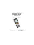
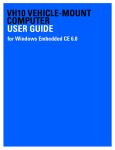
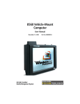
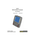
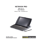
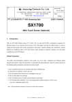
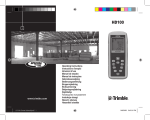
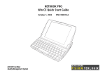
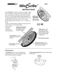
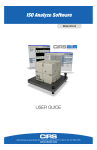
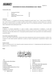
Installation Instruction
Mississauga, Ontario
Canada
DESCRIPTION:
DOCUMENT RAM MOUNT INSTALLATION INSTRUCTION
SHEET
NOTE - FOR SUPPLIER/VENDOR:
•
•
•
THIS DOCUMENT HAS A TOTAL OF 11 PAGES, INCLUDING COVER SHEET
ALL PAGES, EXCLUDING COVER SHEET, ARE REQUIRED FOR CUSTOMER
INSTRUCTION
DO NOT INCLUDE FIRST PAGE IN ASSEMBLY PACKAGE
ITEM GROUP
A00DOC
PRODUCT TYPE
VM0
EDR/O STATUS
X
DRAWN BY:
CHKD. BY:
APPROVALS
DATE
KEN TAYLOR
MAR-22-07
DATE:
OBSOLETE
PROD. / PROJ. ENG.:
ENGINEERING ONLY
MECH. ENG.:
PRE-PILOT
ELEC. ENG.:
BETA
OTHER:
RELEASED
EDR/EDO NO.:
APPROV'D. BY:
INSTALLATION INSTRUCTION FORM:
U:\engdata\RELEASE\MISSISSAUGA PRODUCTS\DO
Blank_Forms\installation instruction_portrait.doc
Mississauga, Ontario
TITLE:
DOCUMENT RAM MOUNT
INSTALLATION INSTRUCTION
SHEET
SIZE
A
DRAWING NO.
REV.
1070404
SHEET
1
OF
A
11
Installation Instruction for MT33XX RAM Mounting Kit
WARNING: Failure to install the mount correctly or modifications to the mount may result in serious
injury or damage to property. Contact Psion Teklogix Technical Support or your Psion Teklogix
representative if you have problems installing this mount. To ensure operator safety, you must use a
calibrated torque wrench and the supplied mounting hardware when fastening the cradle and mount. Use of
this mount in vehicles driven on public roads or highways is prohibited. Contact Psion Teklogix for further
details.
Before mounting an 8515 in a vehicle, there are a number of operator safety issues that require
careful attention. An improperly mounted 8515 may result in one or more of the following:
operator injury, property damage, operator visibility obstruction, operator distraction and/or poor
ease of egress for the operator. Psion Teklogix strongly recommends that you seek professional
mounting advice from the vehicle manufacturer.
When mounting an 8515 use only approved Psion Teklogix mounting hardware and mounting
parts which are specific to the 8515 model purchased. Use of non-approved parts may result in
one or more of the following: operator injury, property damage, operator visibility obstruction,
operator distraction and/or poor ease of egress for the operator.
If it is necessary to mount the 8515 overhead or in any position that could cause injury to the
operator should the unit fall, it is critical that a secondary tether or other failsafe device be
installed.
The following restrictions must be strictly enforced:
•
Do not use the mount and/or the 8515 as a hand-hold. Using the mount in this manner
may cause the person to fall or dislodge the mounting hardware and/or mounts.
•
Do not add weight or attach any other items to the mount or 8515. Additional elements
may fall causing injury or may increase chance of failure and/or damage in mounting
hardware and/or mounts.
Mounts used in industrial or vibration generating environments may be subjected to fatigue, stress
and/or part wear. A periodic inspection of the mounting hardware and mounts should be
performed to ensure parts are retightened to the correct torque, free of fractures, excessive wear
and/or other environmental damage. Any parts found to be unsafe should be removed and
replaced immediately. After inspection or replacement of parts readjust the mount as outlined in
step 4 below and tighten with approved tightening tool (part number 9000594).
Part No. 1070404 Revision A
Sheet 1 of 10
1. Preparation
This articulating mount can be installed in a variety of
orientations (See Figure 7). Select the best orientation for
your specific application. Preferred orientations maintain
the centre of mass of the vehicle mount assembly directly
over the centre of the base (See Figure 1).
Figure 1
Note the tilt & rotation of the cradle can be easily adjusted by the
operator. Ensure that if the handscrew is loosened and the cradle slips,
the operator & any equipment cannot be damaged by it. Also note that
under extreme vibration the mount may slowly 'settle', requiring
readjustment and tightening of the handscrew. Psion Teklogix offers a
tightening tool (part number 9000594) which can be used to minimize
settling. (See Figure 2)
The mounting platform must be of sufficient strength to support 25 kg. Never attach this mount to a plastic
dash or a wooden platform without the appropriate backing plate and bracing. Review the clearance
requirements listed in the 8515 user manual (Under “Mounting Accessories”) when selecting a mounting
location - you must provide operator access at the top, bottom & sides.
Part No. 1070404 Revision A
Sheet 2 of 10
2. Installation
Legend:
A
B
C
D
E
F
G
H
J
L
M
N
P
8515 VMT
RAM Vesa Base
Washer M8 Internal Tooth
Screw M8 x 12 Pan Head
RAM Standard Arm
RAM Circular Base
Screw M8 x 25 Pan Head
Screw M8 x 25 Flat Head
Nut M8 x 1.25
Mounting Kit MT3505
Mounting Kit MT3507
Mounting Kit MT3509
Mounting Kit MT3510
Figure 3: Apply Loctite 243 to Screw (G) threads
(Note: Loctite not supplied by Psion Teklogix). Place
Screw (D) through Washer (C), RAM Vesa Base (B)
and affix to the 8515 VMT (A). Four places.
Torque to 26 in-lbs.
Step 1: Assemble RAM Base to Mounting
Bracket: For assembling the RAM Vesa Base (E) to
the 8515 VMT (A) see Figure 3.
Part No. 1070404 Revision A
Sheet 3 of 10
Step 2: Secure RAM Base to Local Platform and Attach RAM Standard Arm: Use the supplied bolt
hole pattern to drill the required holes in the local platform. Hole diameters must not exceed 10mm [13/32
inches]. Hardware (G, H, C & J) for securing RAM Bases (B or F) to the local platform are recommended
sizes. If replacement hardware is need, it should be consistent with these diameters. All fasteners must use
a suitable locking mechanism to ensure they do not loosen under shock & vibration.
For assembling with RAM Vesa Base see Figure 5.
For assembling with RAM Circular Base see Figure 6.
Figure 5: Place Screw (G) through RAM Vesa
Figure 6: Place Screw (H) through RAM Circular
Base (B), Local Platform, and Washer (C). Affix
with Nut (J). Four places. Torque to 26 in-lbs.
Secure RAM Standard Arm (E) by inserting RAM
Balls in to both ends of arm sockets.
Base (F), Local Platform, and Washer (C). Affix
with Nut (J). Four places. Torque to 26 in-lbs.
Secure RAM Standard Arm (E) by inserting RAM
Balls in to both ends of sockets.
Part No. 1070404 Revision A
Sheet 4 of 10
Step 4: Positioning Mount:
Place 8515 VMT into the
position best corresponding to
RAM hardware used (see figure
7) and tighten by hand until
secure. Refer to first page of
this document for warnings and
proper tightening technique.
Mount orientations shown in
Figure 7 are considered the
preferred configurations for the
Circular Base to Platform and
Vesa Base to Platform.
Figure 7
Optional Mount Kit: One of the mounting kits
shown in Figure 8 may be substituted for the
Vesa Base (B) or the circular base (F) when
mounting to a post or forklift roll cage.
To Install: Mount Clamp Base and Lower Base
around shaft. Place Screw through Clamp and
Lower Base and affix with Nut. Torque to 26 inlbs. Secure RAM Standard Arm (E) by inserting
RAM Balls in to both ends of arm sockets.
Figure 8
Part No. 1070404 Revision A
Sheet 5 of 10
Specifications:
Max. Load: 15kg
Articulating Range: Spherical through 180 degrees.
Shock Rating: Meets IEC60721-3-5 CLASS 5M2 Test Method IEC60068-2-64 Fh
Vibration Rating: Meets IEC60721-3-5 CLASS 5M2 Test Method IEC60068-2-27 Ea
Psion Teklogix Service Parts:
Legend
Item
B
C
D
E
F
G
H
J
Description
RAM Vesa Base
Washer M8 Internal Tooth
Screw M8 x 12 Pan Head
RAM Standard Arm
RAM Circular Base
Screw M8 x 25 Pan Head
Screw M8 x 25 Flat Head
Nut M8 x 1.25
Psion Teklogix
Part Number
9001934
9008800
9004517
9001805
9001804
9004518
9004522
9008801
Part No. 1070404 Revision A
Sheet 6 of 10
Appendix A: Support Services and WorldWide Offices
Support Services
Psion Teklogix provides a complete range of product support services to its customers
worldwide. These services include post-installation technical support and product
repairs.
Canada and USA: Technical Support and Repair Services
In Canada and the U.S.A. these services can be accessed through the Psion Teklogix
Helpdesk. The Helpdesk coordinates repairs, helps you troubleshoot problems over the
phone, and arranges for technicians or engineers to come to your site. Canadian and
U.S. customers may receive access to technical support services, ranging from phone
support to emergency on-site system support, by calling the toll-free number below, or
via our secure web site.
Note: Customers calling the toll-free number should have their Psion Teklogix customer
number or trouble ticket number available.
Voice: 1 800 387-8898
Fax: 1 905 812-6304
Web Site: http://service.psionteklogix.com
WORLD WIDE WEB
www.psionteklogix.com
International Support
For technical support outside of Canada or the U.S.A., please contact your local Psion
Teklogix office.
Part No. 1070404 Revision A
Sheet 7 of 10
Psion Teklogix Worldwide Offices and *Service Centers
North America
Canada (corporate office)
*Psion Teklogix Inc.
2100 Meadowvale Blvd.
Mississauga, Ontario L5N 7J9
Canada
Tel: +1 905 813 9900
[email protected]
Psion Teklogix Inc.
Integration Services Group
Suite 410-13251 Delf Place
Richmond, BC.V6V 2A2
Canada
Tel: 1 604 214 7400
[email protected]
Psion Teklogix Systems
3026 Solandt Road
Kanata, Ontario K2K 2A5
Canada
Tel: 613-592-2592
Fax: 613-592-6778
U.S.A.
*Psion Teklogix Corp.
1810 Airport Exchange Blvd
Suite 500 Erlanger
Kentucky 41018
United States
Tel: +1 859 371 6006
[email protected]
Mexico
Psion Teklogix S.A. de C.V.
Sierra Mojada 626-2
Col. Lomas Barrilaco
D.F. 11010
Mexico
Tel: +5255 5202 6802
[email protected]
Europe
Belgium
Psion Teklogix Benelux
Nieuwe Weg 1
2070 Zwijndrecht
Belgium
Tel: +32 3 250 22 00
[email protected]
Denmark
Psion Teklogix AB (Denmark)
Branch of Psion Teklogix A.B.
Vesterballevej 4-6
DK-7000 Fredericia
Denmark
Tel: +4576240133
[email protected]
France
*Psion Teklogix S.A. [Aix En Provence]
Parc de la Duranne
135, rue René Descartes
BP 421 000
13591 Aix En Provence
Cedex 3
France
Tel: +33 4 42908809
[email protected]
Germany
Psion Teklogix Gmbh
Jakob-Kaiser-Str. 3
47877 Willich Münchheide
Germany
Tel: +49 2154 92820
[email protected]
Italy
Psion Teklogix Srl
Piazza Don Mapelli 75
20099 Sesto S. Giovanni (MI)
ITALY
Tel + 39 02 2412471
Fax + 39 02 24124701
Email: [email protected]
Spain
Psion Teklogix S.L. Espana
WTC Almeda Park-Poligono
Almeda
Placa de la Pau s/n
Edificio no 3, 2 Planta
08940 Cornella de Llobregat
Barcelona
Spain
Tel: +34 93 475 0220
[email protected]
Sweden
Psion Teklogix AB
Stora Badhusgatan 18-20
11 21 Gothenburg
Sweden
Tel: +46 31 339 3090
[email protected]
Switzerland
1A Chemin de la Dent D Oche
Ecublens,VD 1024
Switzerland
Tel: +41 21 694 8010
christophe.francois@psionteklogix
.com
United Kingdom
Psion Teklogix (UK) Limited
Bourne End Business Centre
Cores End Road
Bourne End
Buckinghamshire SL8 5AR
United Kingdom
Tel: +44 1628 648800
[email protected]
Asia
China
Psion Teklogix (Shanghai)
Wireless Technologies Co., Ltd.
Unit 1507-08
Mingshen Building
No.3131 Kai Xuan Rd
Shanghai 200030
China
Tel: +86 21 5407 1991
[email protected]
India
Psion Teklogix Systems India Pvt. Ltd.
V-11, 2nd Floor, Green Park Extn
New Delhi-India, 110016,
phone: +91-11-5107 4500/ 5107
6500 /5107 8500/ 5107 9500
Fax : +91-11-5107 0500
[email protected]
Japan
Psion Teklogix Japan
Ark Mori Building 12F
1-12-32, Akasaka, Minato-ku,
Tokyo 107-6012
Tel: 813 4360-8272
Fax: 813 4360-8201
Email: [email protected]
Singapore
Psion Teklogix Asia Pacific Pte Ltd
152 Beach Road
#22-03/04 Gateway East
Singapore 189721
Tel: +65 6296 2232
Fax: +65 6296 2322
[email protected]
Korea
Psion Teklogix Korea
904 Cresyn Tower
8-24 Jamwon-dong
Seocho-kn, Seoul
Korea
Tel: +822 344 51256
[email protected]
Middle East
Dubai
Psion Teklogix Dubai
P.O. Box 261659 JAFZ
Sheikh Zayed
Emaar Building #2, Unit 615
Dubai
UAE
Tel: +971 4 368 9412
[email protected]
Israel
Psion Teklogix Israel
14 Ze’elon St. Unit 47
Or-Yehuda
Israel 60407
Tel: +972 3 634 8001
[email protected]
Africa
South Africa
Psion Teklogix South Africa
Proprietary Limited
Grd Flr East,Waterfall Edge
Phase 2,Waterfall Park
Bekker Rd.
Midrand 1685
South Africa
Tel: +2711 8057440
[email protected]
8\05
* Authorized Service Center
Part No. 1070404 Revision A
Sheet 8 of 10
Bolt Hole Pattern For RAM Circular Base:
Part No. 1070404 Revision A
Sheet 9 of 10
Part No. 1070404 Revision A
Sheet 10 of 10