1
VH10 VEHICLE-MOUNT
COMPUTER
USER GUIDE
for Windows Embedded CE 6.0
i
VH10 VEHICLE-MOUNT COMPUTER
USER GUIDE
8000275-001
Rev. A
April 2015
ii
VH10 Vehicle-Mount Computer User Guide
Copyright
No part of this publication may be reproduced or used in any form, or by any electrical or mechanical means,
without permission in writing from us. This includes electronic or mechanical means, such as photocopying,
recording, or information storage and retrieval systems. The material in this manual is subject to change
without notice.
The software is provided strictly on an “as is” basis. All software, including firmware, furnished to the user is on
a licensed basis. We grant to the user a non-transferable and non-exclusive license to use each software or
firmware program delivered hereunder (licensed program). Except as noted below, such license may not be
assigned, sublicensed, or otherwise transferred by the user without prior written consent from us. No right to
copy a licensed program in whole or in part is granted, except as permitted under copyright law. The user shall
not modify, merge, or incorporate any form or portion of a licensed program with other program material, create
a derivative work from a licensed program, or use a licensed program in a network without written permission
from us. The user agrees to maintain our copyright notice on the licensed programs delivered hereunder, and
to include the same on any authorized copies it makes, in whole or in part. The user agrees not to decompile,
disassemble, decode, or reverse engineer any licensed program delivered to the user or any portion thereof.
We reserves the right to make changes to any software or product to improve reliability, function, or design.
We do not assume any product liability arising out of, or in connection with, the application or use of any
product, circuit, or application described herein.
No license is granted, either expressly or by implication, estoppel, or otherwise under any of our intellectual
property rights. An implied license only exists for equipment, circuits, and subsystems contained in our
products.
iii
Disclaimer
Every effort has been made to make this material complete, accurate, and up-to-date. In addition, changes are
periodically incorporated into new editions of the publication.
We reserve the right to make improvements and/or changes in the product(s) and/or the program(s) described
in this document without notice, and shall not be responsible for any damages including, but not limited to,
consequential damages, caused by reliance on the material presented.
Our logo, Workabout Pro4 and the names of other products and services provided by us are our trademarks.
Windows® and the Windows Logo are trademarks or registered trademarks of Microsoft Corporation in the
United States and/or other countries.
The Bluetooth® word mark and logos are owned by Bluetooth SIG, Inc. and any use of such marks by us is
under license.
All trademarks used herein are the property of their respective owners.
iv
VH10 Vehicle-Mount Computer User Guide
Revision History
Changes to the original guide are listed below:
Change
--001 Rev A
Date
04/2015
Description
Zebra rebrand.
TABLE OF CONTENTS
Table of Contents
About This Manual ..........................................................................................................................
Text Conventions ............................................................................................................................
Overview of the VH10 Vehicle-Mount Computer ............................................................................
VH10 Views ....................................................................................................................................
xi
xii
xii
xiii
Chapter 1: Basic Operations
VH10 Vehicle-Mount Computer Features ...................................................................................... 1-1
Documents Available ..................................................................................................................... 1-2
Preparing the VH10 for Operation .................................................................................................. 1-2
VH10 Safety Instructions................................................................................................................1-3
The Internal Backup Battery ..........................................................................................................1-3
Switching the VH10 On and Off ...................................................................................................... 1-4
Resetting the VH10......................................................................................................................... 1-4
Performing a Warm Reset.............................................................................................................1-4
Performing a Cold Reset ................................................................................................................1-4
Performing a Clean Start ................................................................................................................1-5
Boot to BooSt..................................................................................................................................1-5
Calibrating the Touchscreen ........................................................................................................... 1-5
Connectivity .................................................................................................................................... 1-5
Chapter 2: Getting To Know Your VH10
Operating System ........................................................................................................................... 2-1
The Keyboard ................................................................................................................................. 2-1
Regular Keys ..................................................................................................................................2-2
Modifier Keys..................................................................................................................................2-3
Activating Modifier Keys...................................................................................................... 2-3
Locking Modifier Keys ......................................................................................................... 2-3
Function Keys and Macro Keys .....................................................................................................2-3
Function Keys ..................................................................................................................... 2-3
Macro Keys ......................................................................................................................... 2-4
The [SYM] Key ...............................................................................................................................2-4
vi
VH10 Vehicle-Mount Computer User Guide
The Keyboard Backlight .................................................................................................................2-4
The Display..................................................................................................................................... 2-4
Adjusting the Display Backlight ......................................................................................................2-4
Calibrating the Touchscreen...........................................................................................................2-5
Indicators ........................................................................................................................................ 2-5
LEDs ..............................................................................................................................................2-5
Power Status LED .............................................................................................................. 2-5
Warning LED ...................................................................................................................... 2-6
Onscreen Indicators .......................................................................................................................2-6
Audio Indicators..............................................................................................................................2-7
Scanners and Imagers.................................................................................................................... 2-7
Scanning Techniques .....................................................................................................................2-7
Scan LED Indicators.......................................................................................................................2-8
Troubleshooting ..............................................................................................................................2-8
Operating Two Dimensional (2D) Imagers.....................................................................................2-8
Windows Embedded CE 6.0........................................................................................................... 2-9
Navigating in Windows Embedded CE and Applications ..............................................................2-9
Navigating Using a Touchscreen ........................................................................................ 2-9
Navigating Using the Keyboard .......................................................................................... 2-9
The Windows Classic Shell Startup Desktop .................................................................................2-10
The Taskbar ........................................................................................................................ 2-11
The Start Menu ................................................................................................................... 2-12
The Kiosk Desktop Shell................................................................................................................. 2-16
Restoring the Windows Classic Shell.............................................................................................2-18
General Maintenance ..................................................................................................................... 2-19
Caring for the Touchscreen ............................................................................................................2-19
Cleaning the VH10 .........................................................................................................................2-19
Chapter 3: Configuration
Overview of Software...................................................................................................................... 3-1
Software Advantage .......................................................................................................................3-1
Microsoft Software ..........................................................................................................................3-1
Control Panel .................................................................................................................................. 3-2
Control Panel Applications .............................................................................................................3-2
App Launch Keys............................................................................................................................ 3-5
Bluetooth® Setup.............................................................................................................................. 3-6
Paired .............................................................................................................................................3-7
Device ............................................................................................................................................3-8
Discovering and Removing Devices ................................................................................... 3-9
Filtering By Class of Device (COD)..................................................................................... 3-9
Device Pop-up Menu .......................................................................................................... 3-9
Pairing a Device.................................................................................................................. 3-10
Servers ..........................................................................................................................................3-11
Mode ..............................................................................................................................................3-12
About ..............................................................................................................................................3-13
Bluetooth Quick-Pairing..................................................................................................................3-13
Table of Contents vii
The Bluetooth GPRS WAN Connection.........................................................................................3-14
Certificates ...................................................................................................................................... 3-17
Data Transfer between VH10 and a PC ......................................................................................... 3-18
Using Microsoft ActiveSync............................................................................................................3-18
Using Windows Mobile Device Center...........................................................................................3-18
Display Properties........................................................................................................................... 3-18
Background ...................................................................................................................................3-18
Appearance ...................................................................................................................................3-19
Backlight ........................................................................................................................................3-19
Screen Blanking ............................................................................................................................3-20
Dr. Debug ....................................................................................................................................... 3-21
Status..............................................................................................................................................3-21
Utilities ............................................................................................................................................3-21
Settings...........................................................................................................................................3-22
Error Reporting ............................................................................................................................... 3-22
Input Panel...................................................................................................................................... 3-23
Keyboard Properties ...................................................................................................................... 3-24
Key Repeat.....................................................................................................................................3-24
Backlight .........................................................................................................................................3-25
One Shot Modes ............................................................................................................................3-26
Macro Keys.....................................................................................................................................3-27
Unicode Mapping ...........................................................................................................................3-28
Scancode Remapping....................................................................................................................3-29
Lock Sequence...............................................................................................................................3-31
Manage Triggers ............................................................................................................................. 3-32
Trigger Mappings............................................................................................................................3-32
Add and Edit Trigger Mapping........................................................................................................3-33
Microphone .................................................................................................................................... 3-34
TekTerm Client ................................................................................................................................ 3-35
PartnerUp........................................................................................................................................ 3-35
Power Properties ............................................................................................................................ 3-35
Status .............................................................................................................................................3-36
Power Saving Suspend..................................................................................................................3-36
Advanced .......................................................................................................................................3-37
Built-in Devices...............................................................................................................................3-37
Wakeup Sources ............................................................................................................................3-38
Battery Health.................................................................................................................................3-38
Kiosk Access................................................................................................................................... 3-40
Administrator Password .................................................................................................................3-41
Shell Settings..................................................................................................................................3-42
Restrictions ....................................................................................................................................3-43
Control Panel Settings....................................................................................................................3-44
Import/Export to File .......................................................................................................................3-45
Quick Defrost (Heater Settings for VH10f)...................................................................................... 3-45
Settings..........................................................................................................................................3-46
Heater Info.....................................................................................................................................3-47
viii
VH10 Vehicle-Mount Computer User Guide
Remote Desktop Connection ......................................................................................................... 3-48
Scanners......................................................................................................................................... 3-48
Decoded Scanners .........................................................................................................................3-48
Options ..........................................................................................................................................3-49
Double Click Parameters .................................................................................................... 3-49
Display Parameters............................................................................................................. 3-49
Data Handling ..................................................................................................................... 3-50
Translations ...................................................................................................................................3-51
Case Rules ......................................................................................................................... 3-52
Ports ...............................................................................................................................................3-52
Ports ................................................................................................................................... 3-53
Storage Manager ............................................................................................................................ 3-54
Formatting a Memory Card ............................................................................................................3-54
Creating Partitions ..........................................................................................................................3-55
Partition Management ....................................................................................................................3-56
Stylus Properties............................................................................................................................. 3-57
Double-Tap .....................................................................................................................................3-57
Calibration.......................................................................................................................................3-58
Touch ..............................................................................................................................................3-58
System Properties .......................................................................................................................... 3-58
Total Recall ..................................................................................................................................... 3-59
Creating a Backup ..........................................................................................................................3-60
Creating a Clone.............................................................................................................................3-60
Managing Profiles...........................................................................................................................3-61
Viewing a Profile ................................................................................................................. 3-61
Profile Options .................................................................................................................... 3-62
Deleting a Profile ............................................................................................................................3-64
TweakIt ........................................................................................................................................... 3-64
Advanced........................................................................................................................................3-64
Advanced CE Services Settings ......................................................................................... 3-64
Advanced Interface and Network Settings .......................................................................... 3-65
Advanced Services Settings ............................................................................................... 3-65
Registry Editor ................................................................................................................................3-66
Volume & Sounds Properties.......................................................................................................... 3-66
Volume Adjustments.......................................................................................................................3-66
Wi-Fi Config .................................................................................................................................... 3-67
Wi-Fi Config: Status .......................................................................................................................3-67
Wi-Fi Config: Configure .................................................................................................................3-67
Manually Creating a Network .............................................................................................. 3-68
Authentication Mode ........................................................................................................... 3-68
Encryption ........................................................................................................................... 3-69
EAP .................................................................................................................................... 3-70
Verify Server Certificate ...................................................................................................... 3-70
Enable OPMK ..................................................................................................................... 3-71
Connecting the Wireless Network ....................................................................................... 3-71
Configuring TCP/IP.........................................................................................................................3-72
IP Address .......................................................................................................................... 3-72
Name Servers ..................................................................................................................... 3-73
Table of Contents ix
Wi-Fi Config: Advanced .................................................................................................................3-74
Country Options .................................................................................................................. 3-74
Use Windows to configure my wireless settings (Wireless Zero Config) ............................ 3-74
Network Type ...................................................................................................................... 3-74
11n Mode ............................................................................................................................ 3-75
11n – Block Ack................................................................................................................... 3-75
Power Save Mode............................................................................................................... 3-75
Roaming - RSSI Threshold ................................................................................................. 3-75
Roaming - AP Discovery ..................................................................................................... 3-75
Roaming - Packet Loss ....................................................................................................... 3-75
2.4GHz Channel Selection.................................................................................................. 3-75
Concluding the Wi-Fi Configuration .................................................................................... 3-75
Monitoring the Network Connection...............................................................................................3-76
WiFi Connect A.R.C........................................................................................................................ 3-76
Chapter 4: Accessories
Accessories .................................................................................................................................... 4-1
Antennas.........................................................................................................................................4-1
Mounts ............................................................................................................................................4-1
Power Supplies and Cables ...........................................................................................................4-2
Miscellaneous Accessories ............................................................................................................4-2
External Barcode Readers.............................................................................................................. 4-2
Entering Data with the Barcode Reader ........................................................................................4-3
Bluetooth Peripherals .................................................................................................................... 4-3
Antennas......................................................................................................................................... 4-3
Possible VH10 Antenna Locations.................................................................................................4-3
Linking a VH10 to an Ethernet Network.......................................................................................... 4-5
Network Access..............................................................................................................................4-6
VH10 Mounting Accessories........................................................................................................... 4-6
The MT43XX RAM Mount Kit.........................................................................................................4-7
Installation ........................................................................................................................... 4-8
Positioning the VH10........................................................................................................... 4-10
Optional Mount Kits............................................................................................................. 4-10
The MT3410 Heavy Duty Mount Kit...............................................................................................4-11
Mount Assembly.................................................................................................................. 4-11
Attaching the VH10 to the Heavy Duty Mount..................................................................... 4-13
Positioning the VH10........................................................................................................... 4-14
The MT4200 Quick Release Mount ..............................................................................................4-14
The MT4205 Mounting Plate for MT4200 Quick Release Mount ..................................................4-16
The MT4210 Adaptor Bracket Kit ..................................................................................................4-16
The MT1002 Cantilever Mount Kit .................................................................................................4-16
Mount Assemblies............................................................................................................... 4-17
VH10 Vehicle Installation ................................................................................................................ 4-20
Wiring Guidelines ...........................................................................................................................4-20
Non-Vehicle Installations ................................................................................................................4-21
Wiring Vehicle Power to the VH10 .................................................................................................4-21
Installing the Power Pre-regulator....................................................................................... 4-22
x
VH10 Vehicle-Mount Computer User Guide
Power On/Off with Ignition Option: Wiring........................................................................... 4-22
Screen Blanking Option: Wiring .......................................................................................... 4-24
Appendix A: VH10 Specifications
The VH10 Vehicle-Mount Computer ............................................................................................... A-1
Hardware .................................................................................................................................. A-1
Power Management.................................................................................................................. A-2
Environmental ........................................................................................................................... A-2
Regulatory Approvals................................................................................................................ A-3
External Barcode Scanners ............................................................................................................ A-3
Wireless Radios.............................................................................................................................. A-3
802.11a/b/g/n Standard Radio .................................................................................................. A-3
Bluetooth Radio ........................................................................................................................ A-5
Antennas................................................................................................................................... A-6
RA1202 Narrowband Radio ...................................................................................................... A-8
Appendix B: Port Pinouts
Ports Diagram ................................................................................................................................. B-1
Serial Ports Interface Pinout (UART RS-232)................................................................................. B-2
Enhanced USB1 Port Interface Pinout ........................................................................................... B-3
Enhanced Powered USB2 Port Interface Pinout ............................................................................ B-3
Appendix C: Wireless Zero Config Settings
Wireless Information ....................................................................................................................... C-1
Wireless Statistics .................................................................................................................... C-2
Wireless Information ................................................................................................................ C-2
Assigning An IP Address ................................................................................................................ C-5
Name Server............................................................................................................................. C-5
Advanced Features......................................................................................................................... C-5
Rearranging Preferred Networks .............................................................................................. C-5
Deleting a Preferred Network.................................................................................................... C-6
Changing Network Properties ................................................................................................... C-6
Appendix D: Narrowband Radio Configuration
Narrowband Radio Setup ............................................................................................................... D-1
Basic Tab ........................................................................................................................................ D-2
Channels Tab.................................................................................................................................. D-3
Advanced Tab ................................................................................................................................. D-6
Tune Poll Settings........................................................................................................................... D-6
Appendix D: Tune Poll Settings
Statistics Screen ............................................................................................................................. D-6
Index. . . . . . . . . . . . . . . . . . . . . . . . . . . . . . . . . . . . . . . . . . . . . . . . . . . . . . . . . .. . . . . . . . . . . . . . . . . . . . . . . . . . . . . . . . . . . . . . . . . . . . . . . . . . I
ABOUT THIS GUIDE
ABOUT THIS GUIDE
About This Guide
This guide applies to the following model numbers:
•
8516
•
8516N
This user guide describes the configuration, operation, and maintenance of the VH10
Vehicle-Mount Computer.
Chapter : About This Guide. provides a basic overview of the VH10.
Chapter 1: Basic Operations. describes the steps required to get the VH10 ready for operation.
Chapter 2: Getting To Know Your VH10. describes VH10 features, including the keyboard features, the display, etc. This chapter also describes the Microsoft® Windows® Embedded CE 6.0 desktop, and
how to change the appearance and actions of the desktop from Windows Classic Shell to the
Kiosk Shell.
Chapter 3: Configuration. describes the programs and applications accessed through two main areas from
the Desktop Start Menu: Programs and Settings>Control Panel. The software includes both Software Advantage and Microsoft programs, and details how to use them to configure the VH10,
along with Power Properties, Bluetooth, etc. This chapter also details the Kiosk program, which
enables you to customize your computer settings.
Chapter 4: Accessories. describes the peripherals and accessories available for your VH10 Vehicle-Mount
Computer.
Appendix A: VH10 Specifications. lists the specifications for your VH10 computer, radios, and battery.
Appendix B: Port Pinouts. describes the VH10 pinouts.
Appendix C: Wireless Zero Config Settings. outlines the steps used to configure your radio using Windows
Zero Config.
Appendix D: Narrowband Radio Configuration. describes setting up the RA1202 Narrowband radio.
xii
VH10 Vehicle-Mount Computer User Guide
Text Conventions
NOTE Notes highlight additional helpful information.
These statements provide particularly important instructions or additional information that
is critical to the operation of the equipment.
IMPORTANT
WARNING!
These statements provide critical information that may prevent physical injury,
equipment damage or data loss.
Overview of the VH10 Vehicle-Mount Computer
The VH10 is a modular, industrial vehicle-mounted computer, running the Microsoft Windows Embedded CE
6.0 operating system. It is intended for use in commercial and industrial applications with a focus on real time
wireless data transactions with options suiting materials handling applications in warehouses, manufacturing
facilities, ports, and yards. A wide range of data input capabilities are supported through a variety of imager,
RFID and barcode scanner options.
The optional VH10f freezer model includes heating hardware to be used in cold environments to prevent
condensation from developing on or inside the VH10. The heaters keep the display clear of frost, the keyboard
from freezing, and the ports dry. In addition, the heater clears fog from the display panel when the computer is
moved in and out of cold environments. For details, see Quick Defrost (Heater Settings for VH10f) on
page 3-45.
NOTE For product specifications, refer to Appendix A: VH10 Specifications.
Processor and Memory
•
Texas Instruments® OMAP3® Processor 800 MHz
•
Flash ROM: 1 GB
•
RAM: 512 MB
Operating System
•
Microsoft® Windows® Embedded CE 6.0
Bundled Applications
•
Internet Explorer® 6
•
Windows Mobile Device Center
•
WordPad®, ActiveSync®
Supported Applications*
•
TekTerm Client - Terminal Emulation
•
Wavelink TN - Terminal Emulation
* Note that Tekterm Client is the only application available when a Narrowband radio is installed in the unit.
About This Guide
xiii
Device Management and Provisioning
•
Kiosk
•
Total Recall, TweakIt, Dr. Debug – Utilities
•
SOTI MobileControl – Mobile Device Management
- Easy configuration management and provisioning platform.
- Powerful remote control and troubleshooting functionality.
- Integrated real time geofencing and location services.
- Advanced device security, user authentication and lockdown features.
User Interface
•
Colour/Touch Display 20.32 cm (8") diagonal
- VGA (800 x 480) Transflective
- High visibility option: superior sunlight visibility with 640 cd/m2 brightness
•
Touchscreen
- Passive stylus or finger operation
- Optional heater
•
Keyboard
- 67-key QWERTY and AZERTY available
- 12 dedicated function keys
- LED backlight
•
Voice and Audio
- High volume beeper: 93 dBA
- Optional Push-to-Talk speaker/microphone
Wireless Connectivity
•
802.11a/b/g/n Standard Radio - with Bluetooth® coexistence (Bluetooth V2.0 + EDR)
•
RA1202 Narrowband Radio
•
CCX v4
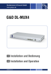
VH10 Views
The following figures show the VH10 — for detailed illustrations, please see VH10 Vehicle-Mount Computer
Features on page 1-1.
xiv
VH10 Vehicle-Mount Computer User Guide
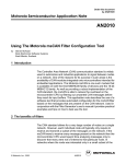
Figure 1
VH10 Front View (standard unit)
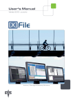
Figure 2
VH10f Front View (freezer unit)
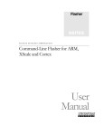
Figure 3
Bottom (Ports) View
CHAPTER 1 BASIC OPERATIONS
BASIC OPERATIONS
1
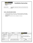
VH10 Vehicle-Mount Computer Features
Figure 1-1 Front View
Power button
Optional external
antenna connector (1)
Optional external
antenna connectors (2)
Power LED
Warning LED
Function keys
and
Macro keys
Display
Function keys
Orange
Modifier key
Macro keys
Blue
Modifier key
SYM key
ENTER/POWER key
1-2
VH10 Vehicle-Mount Computer User Guide
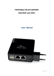
Figure 1-2 Bottom View (cable bay cover in place)
Latch each side of
cable bay cover
Cable bay cover
Power cable
Beeper
UART RS-232 ports
Figure 1-3 Bottom View (cable bay cover removed)
Vent
Strain relief
brackets
Cable bay
UART RS-232 ports
Audio jack
Powered USB host port
USB host port
Power cable
Beeper
Ground lug
Documents Available
To see a current list of documents and download what you need, please go to the Knowledge Base on the
IngenuityWorking community website:
http://www.ingenuityworking.com/knowledge/w/knowledgebase/product-manuals.aspx
Preparing the VH10 for Operation
Typically the VH10 Vehicle-Mount Computer is configured at the factory and arrives ready for use. Although
the VH10 is equipped with a MicroSD card on the MLB, this card is not intended for user modification.
Basic Operations 1 - 3
VH10 Safety Instructions
WARNING!
IT IS CRITICAL that this information be reviewed and that any guidelines applicable
to your VH10 be strictly followed.
•
The cord should be installed in the vehicle so that it is not subjected to damage or stress.
•
Use of a power cord that is not recommended or sold by the manufacturer may result in fire, electric shock,
or personal injury.
•
An extension cord should not be used unless absolutely necessary. Use of an improper extension cord
could result in fire or electric shock. If an extension cord must be used, make sure:
•
The plug pins on the extension cord are the same number, size, and shape as those on the adaptor.
•
The extension cord is properly wired and in good electrical condition and that the wire size is larger than
16 AWG.
•
When the unit is connected to the vehicle or AC adaptor, the mains power cord shall comply with National
safety regulations of the country where the equipment is to be used.
•
Do not use the AC adaptor with a damaged cord or plug. Replace it immediately.
•
Do not operate the AC adaptor if it has received a sharp blow, been dropped, or otherwise damaged in any
way; it should be inspected by qualified service personnel.
•
Do not disassemble the AC adaptor; it should be repaired by qualified service personnel. Incorrect reassembly may result in electric shock or fire.
•
To reduce risk of electric shock, unplug the computer from the vehicle, or AC adaptor from the outlet,
before attempting any maintenance or cleaning.
•
Do not expose the vehicle DC adaptor cables or AC adaptor to rain or snow.
The Internal Backup Battery
The VH10 Vehicle-Mount Computer is equipped with a supercapacitor that will provide emergency memory
retention to the unit for up to five minutes in case of power disruption. While the VH10 will not be operational
when external power is removed, the memory content is preserved during this period. It also provides up to
one week of real-time clock backup.
An optional internal rechargeable UPS battery is available to support limited normal operation during a power
loss or brown-out scenario. The optional UPS battery is not user-accessible and should be serviced by authorized personnel.
NOTE To maximize battery run time when the VH10 is on UPS Battery Power, the display backlight is
automatically dimmed, the keyboard backlight is turned off, heaters are automatically switched off,
and the powered external ports are limited to a total of 1A.
Please see the following sections for detailed battery information:
•
Calibration and power settings: Power Properties on page 3-35.
•
Specifications: Power Management on page A-2.
The optional UPS battery can provide one hour run time (typical) and 15 minutes run-time (minimum). UPS
run-time will be dependent on radio usage and the peripherals connected to the VH10 external ports during
UPS mode. The UPS battery run-time may reduce as operating temperature cools. Note that charging of the
UPS battery is fully controlled by the VH10, based on battery condition and environmental temperature.
Charging will only occur when the temperature of the battery is between 0° C and 40° C.
1-4
VH10 Vehicle-Mount Computer User Guide
NOTE If a UPS battery is installed and a brown-out situation occurs, the VH10 will enter UPS mode in
which the terminal will continue to run normally with limited functionality (e.g. display backlight
dimmed, keyboard backlight and heaters turned off). The VH10 will switch back to normal mode
when external power is restored.
Switching the VH10 On and Off
Pressing the Power button on the top left of the VH10 connects the unit to external power and boots the
computer. Pressing the Power button again disconnects the unit from external power, and therefore draws no
power from the vehicle.
When the VH10 is connected to external power and in Suspend state (Display Screen off, Power status LED
colour is solid amber), holding down the [ENTER] key on the keyboard wakes the computer. Pressing the
[BLUE] key then the [ENTER] key puts the unit into Suspend, which still allows it to draw power from
the vehicle.
NOTE When pressing the [ENTER] key to wake the unit from Suspend, the screen in which you
were working before the computer entered suspend state is displayed.
Resetting the VH10
To perform a warm or cold reset, you can access the menu by going to the Windows menu Start>Shutdown.
Alternatively you can use the keyboard shortcuts described below.
NOTE If your Desktop is switched to the Kiosk Shell (refer to The Kiosk Desktop Shell on page 2-16),
resetting the unit is done solely by use of the keyboard shortcuts.
Performing a Warm Reset
During a warm reset, running programs are halted. The contents of the file system, RAM Disk, Flash Disk, and
the registry are preserved.
• Press and hold down the [BLUE] key and the [ENTER] key simultaneously for a minimum of
six seconds.
NOTE You need to reset your VH10 after configuring the radio by switching between Windows Zero
Config and WiFi Config.
Performing a Cold Reset
A cold reset reinitializes all hardware. All RAM including the RAM Disk is erased. Non-volatile storage such as
the Flash Disk is preserved, as is the file system.
To execute a cold reset:
• Press and hold down the [ORANGE] key, the [BLUE] key, and the [ENTER] key, simultaneously for a
minimum of six seconds.
NOTE As part of the normal Windows Embedded CE cold boot process, the screen may go blank for a
few seconds after the splash screen loading bar reaches the end. The desktop is displayed after
a few moments.
Basic Operations 1 - 5
Performing a Clean Start
A clean start returns the VH10 to factory settings, flushes the registry keys, and deletes volatile storage and the
file system. The Flash Disk is preserved.
•
Press and hold down the [BLUE] key, the [ENTER] key, and the [SPACE] key simultaneously for a
minimum of six seconds.
The VH10 displays the Boot to BooSt menu.
•
Type .clean. (or .25326)
Boot to BooSt
If you choose Boot to BooSt, the BooSt menu is loaded.
•
Press and hold down the [BLUE] key, the [ENTER] key, and the [SPACE] key for a minimum of
six seconds.
•
Press [1] to launch the OS.
Calibrating the Touchscreen
NOTE The touchscreen function can be turned off (see Touch on page 3-58).
The VH10 touchscreen feature is factory-calibrated and ready-to-go; however, over time the touchscreen operating parameters may change, and it may need to be recalibrated for correct operation. Refer to Calibrating the
Touchscreen on page 2-5 for details.
Connectivity
Data transfer options vary slightly depending on the type of operating system installed in your PC. Various
options exist depending on whether you are using Windows XP or earlier, Windows Vista®, Windows 7 or later.
For information on connecting the VH10 to a PC, please refer to Data Transfer between VH10 and a PC on
page 3-18.
The VH10 contains an integrated 802.11a/b/g/n radio module. The Wi-Fi Config application is used to configure
the radio for one or more wireless network profiles. To configure the radio, follow the steps outlined under the
heading Wi-Fi Config on page 3-67.
To configure your Bluetooth settings, please go to Bluetooth® Setup on page 3-6.
To see the radio specifications, please go to Wireless Radios on page A-3.
CHAPTER 2 GETTING TO KNOW YOUR
VH10
GETTING TO KNOW YOUR VH10
2
Operating System
•
Microsoft® Windows® Embedded CE 6.0
The Keyboard
The VH10 is available with an integrated keyboard in either QWERTY or AZERTY alphanumeric keyboard
layout. It features 67 keys, 12 direct function keys, and an LED backlight.
Most of the keys on the keyboard operate much like a desktop computer. Where a key or key function is not
consistent with the PC keyboard, those differences are described in the following sections.
There are a number of modifier keys that provide access to additional keys and system functions, as described
in Modifier Keys on page 2-3.
The [BLUE] modifier key provides access to additional keys and system functions. These functions are colour
coded in blue print on the key caps.
2-2
VH10 Vehicle-Mount Computer User Guide
Figure 2-1 Keyboard Layout
Function keys
and
Macro keys
Function keys
Orange
Modifier key
Macro keys
Blue
Modifier key
SYM key
Brightness +/- keys
Volume +/- keys
ENTER/POWER key
Regular Keys
The Arrow Keys
The [Arrow] keys are located near the bottom of the keyboard, and are represented on the keyboard as triangles pointing in different directions. The [Arrow] keys move the cursor around the screen in the direction of the
arrow: up, down, left and right. The left arrow key should not be confused with the backspace [DEL] key which
is depicted as a left arrow. The cursor is the flashing box or underline character that indicates where the next
character you type will appear.
The [DEL] Key
The [DEL] key (represented on the keyboard as an arrow pointing left) is the backspace key that moves the
cursor one character to the left, erasing the previous key stroke.
The [BLUE] + [DEL]) keys erase the character at the current cursor position.
The [SHIFT] Key
The [SHIFT] key is used to display uppercase alpha characters. Pressing [BLUE][SHIFT] turns the [CAPS] key
on so that all alpha characters are printed in uppercase until the [BLUE][SHIFT] sequence is pressed again.
The [CTRL] and [ALT] Keys
The [CTRL] and [ALT] keys modify the function of the next key pressed and are application dependent.
Pressing either key twice locks it 'on' (it appears underlined on the Taskbar). Pressing the key once again
unlocks it.
The [TAB] Key
Typically, the [TAB] key moves the cursor to the next field to the right or downward.
The [ESC] Key
Generally, this key is used as a keyboard shortcut to close the current menu, dialog box, or activity.
Getting To Know Your VH10 2 - 3
The [SPACE] Key
Pressing this key inserts a blank space between characters. In a Windows dialog box, pressing the [SPACE]
key enables or disables a check box.
The [INS] Key
The [INS] key inserts a character at the cursor position.
Modifier Keys
The [SHIFT], [CTRL], [ALT], [BLUE] and [ORANGE] keys are modifier keys that change the function of the next
key pressed. The functions related to the [BLUE] modifier key are colour-coded in blue print above the
keyboard keys.
The [SHIFT], [CTRL], and [ALT] keys operate much like a desktop keyboard except that they are not chorded
(two keys held down simultaneously). The modifier key must be pressed first followed by the key whose function you want modified.
Activating Modifier Keys
When a modifier key is pressed, it is shown in the softkey bar at the bottom of the screen, making it easier to
determine whether a modifier key is active. For example, if the [CTRL] key is pressed, Ctrl is displayed at the
bottom of the unit screen. Once the next key is pressed, the modifier key becomes inactive and disappears
from the taskbar.
Locking Modifier Keys
When a modifier key is pressed twice, it is ‘locked’ on. A ‘locked’ modifier key is displayed underlined in the
taskbar. For example, pressing the [BLUE] key twice locks it on — it is displayed as an underlined blue box in
the taskbar at the bottom of the computer screen. The same is true of the [ORANGE] key, which is shown as
an underlined orange box in the taskbar.
The locked modifier key will remain active until it is pressed a third time to unlock or turn it off. Once a modifier
key is unlocked, the underline representation at the bottom of the screen is no longer displayed.
NOTE The locking function of the modifier keys can be changed so that pressing a key once will lock
the key on.
If you disable the ‘One Shot’ function of the key, pressing it once will lock the key ‘on’. Pressing
the same key a second time will unlock or turn it ‘off’. Refer to One Shot Modes on page 3-26
for details.
Function Keys and Macro Keys
In addition to the standard keyboard functions (see The Keyboard on page 2-1), the VH10 supports function
keys and macro keys.
All function keys and macro keys can be custom defined for each application. The TekTerm Client application
utilizes these keys (for detailed information, see the TekTerm Client Software User Manual, PN 8000073).
Function Keys
Function keys perform special, custom-defined functions within an application. These keys are accessed by
pressing one of the dedicated function keys on the keyboard, or through the appropriate [ORANGE] or [BLUE]
key sequence.
To access the orange or blue function keys, first press the [ORANGE] or [BLUE] key followed by the appropriate function key.
2-4
VH10 Vehicle-Mount Computer User Guide
Function keys [F1] through [F12] can be used with the Windows Embedded CE operating system or another
application. The additional function keys, [F13] through [F30] along with the macros, are not used as part of the
Windows Embedded CE operating system.
Macro Keys
IMPORTANT
Refer to Macro Keys on page 3-27 for details about creating macros.
The VH10 keyboard is equipped with a series of macro keys that can be programmed to replace frequently
used keystrokes, along with the function of executable keys like the [ENTER] key, the [BACKSPACE] key, any
function key, arrow key, etc.
The [SYM] Key
The Symbol key is represented on the keyboard by the characters [SYM] and provides access to commonly
used symbolic characters. Pressing the key brings up the Symbol soft input panel (SIP) onscreen keyboard,
with symbols mapped to each key. If you wish to adjust the settings for the pop-up screen, modify the file softinputpanel.xml, located in the Windows folder. Reboot the computer for the new settings to take effect.
The Keyboard Backlight
The intensity of the keyboard backlight and the conditions under which this backlight is activated can be configured by opening the Keyboard icon in the Windows Embedded CE Control Panel. The behaviour of the
keyboard backlight is tailored in the Keyboard Properties dialog box. Refer to Backlight on page 3-25 for details
about this option.
NOTE To maximize battery run time when the VH10 is on UPS Battery Power, the keyboard backlight
automatically turns off. For details see Power Saving Suspend on page 3-36.
The Display
The VH10 is equipped with display backlighting to improve character visibility in low light conditions. The backlight switches on when a key is pressed or the touchscreen is tapped.
Adjusting the Display Backlight
The behaviour of the display backlight and the intensity of the backlight can be specified in the Display Properties dialog box in the Control Panel.
NOTE Refer to Backlight on page 3-19 for details about the Display Properties dialog box.
Getting To Know Your VH10 2 - 5
Calibrating the Touchscreen
If you find that the stylus pointer is not accurate when you tap on an item on the VH10 screen, use the Stylus
Properties dialog box in the Control Panel to recalibrate the screen.
•
In the Control Panel, choose the Stylus icon to display the Stylus Properties window.
•
Select the Calibration tab, and then choose the Recalibrate button.
•
Follow the directions on the calibration screen to calibrate the screen.
Indicators
The VH10 uses LEDs (Light Emitting Diodes), onscreen messages, and audio tones as indicators.
LEDs
The VH10 is equipped with two coloured LEDs. This section outlines the conditions these LEDs indicate.
Figure 2-2 LED Status Indicators
Power Status
Warning
Power Status LED
The Power LED indicates system notifications and operating system status. It is also available for user-loaded
custom Windows Embedded CE applications.
2-6
VH10 Vehicle-Mount Computer User Guide
Operating LED Behaviour
Function
OFF
The unit has no power (e.g. external power not
available, master power switch turned off). In this
state, pressing the [ENTER] key on the keyboard
will not wake up the unit.
Solid Amber with Slow Flashing Green
The unit is ON, but operating from UPS battery.
Solid Green
The unit is ON, operating from external power.
Solid Amber with Slow “Blipping” Green
(A 5 second period with 2% duty cycle:
green is on for 0.1 sec, off for 4.9 sec)
The unit is in Suspend, operating from UPS battery,
and cannot be turned on until external power is
present.
Warning LED
The red Warning LED indicates a fault situation, as shown here:
Operating LED Behaviour
Function
OFF
No battery/charger faults.
Solid Red
Battery temperature is out of range for charging.
Blinking Red
Any other battery/charging fault, e.g. communication
fault, charge timeout, defective battery pack.
Onscreen Indicators
The taskbar at the bottom of the screen displays a variety of system status indicators, including the Input Panel
button if you have chosen to show that option in the Taskbar and Start Menu settings.
Figure 2-3 Taskbar
The taskbar changes dynamically, and only those icons that are applicable are displayed. For example, if a
radio is not installed in your VH10, the radio signal icon is not displayed in the taskbar.
Windows® Start Menu
If you are using the touchscreen, you can either tap the Windows icon at the bottom left of the screen, or press
the [BLUE] + [MENU] key combination to display the Start Menu, and then tap on the desired application.
Modifier Key Indicators
[SHIFT], [CTRL], [ALT], [BLUE], and {ORANGE] are modifier keys that have onscreen indicators to show when
a key is active or locked. If a modifier key is pressed once to activate it, the key is displayed in the taskbar, for
example, pressing the [BLUE] key once displays a solid blue box in the taskbar. If a modifier key is pressed
twice, it is ‘locked on’ and the onscreen indicator is displayed with its icon underlined, for example, pressing
Getting To Know Your VH10 2 - 7
[BLUE] twice displays solid blue box with an underline in the taskbar. For detailed information on these keys
and all the keyboard functions, please refer to The Keyboard on page 2-1.
802.11 Radio Signal Quality
Increasing radio signal quality is represented by longer, filled bars within this icon.
Good
Reception
Weak
Reception
No Radio
Link
Bluetooth Radio
This icon displayed in the taskbar represents the installed Bluetooth radio.
Input Panel
You can tap the Input Panel icon to activate the soft keyboard application.
Audio Indicators
The VH10 beeper emits a sound when a key is pressed, a keyboard character is rejected, scan input is
accepted or rejected, an operator’s entry does not match in a match field, etc. To adjust the volume, see
Volume Adjustments on page 3-66.
Scanners and Imagers
IMPORTANT
It is critical that you review the “Laser Warnings” in the VH10 Vehicle-Mount Computer
Regulatory & Warranty Guide (PN 8000279) before using any of the scanners described
in this chapter.
The VH10 supports a wide range of scanner options to address a variety of user application requirements.
Decoded scanners must be configured by scanning special configuration barcodes. In these cases, the
scanner manufacturer provides programming manuals for configuration purposes. Refer to the following
sections for detailed information:
•
Supported Types: Handheld scanners and imagers connected via USB, RS-232, or Bluetooth, see External Barcode Scanners on page A-3.
•
Interface: FF UART RS-232 port or USB port, see Appendix B: Port Pinouts.
•
Configuration: Scanners on page 3-48 and Manage Triggers on page 3-32.
•
Scanning Techniques on page 2-7 below outlines the mechanics of a successful scan.
•
Troubleshooting on page 2-8 below provides some helpful suggestions should the scan fail.
Scanning Techniques
•
Hold the scanner at an angle. Do not hold it perpendicular to the barcode.
•
Do not hold the scanner directly over the barcode. In this position, light can reflect back into the scanner’s
exit window and prevent a successful decode.
•
Scan the entire barcode. If you are using a 1D or PDF laser scanner, make certain that the scan beam
crosses every bar and space on the barcode, including the margins on either end of the symbol.
2-8
VH10 Vehicle-Mount Computer User Guide
•
If you are using a 2D imaging scanner, make certain the red, oval shaped framing mark is centered within
the barcode you want to scan.
•
When using imaging scanners, do not move the scanner while decoding the barcode. Movement blurs
the image.
•
Hold the scanner farther away for larger barcodes.
•
Hold the scanner closer for barcodes with bars that are close together.
Scan LED Indicators
External scanners have integrated LED indicators that are not controlled by the VH10.
Troubleshooting
If the scanner is not working, investigate the following:
•
Is the VH10 on?
•
Check that the scanner settings are correctly configured (see Scanners on page 3-48).
•
Check the barcode to make sure it is not damaged. Try scanning a different barcode to verify that the
problem is not with the barcode.
•
Check that the barcode is within the proper range.
•
Does the computer display the warning without scanning? This suggests a hardware problem in the VH10.
•
Is the laser beam scanning across the barcode?
•
Once the scan beam has stopped, check the scanner window for dirt or fogging.
Operating Two Dimensional (2D) Imagers
An imager scanner takes a snap shot of a single barcode or multiple barcodes (at one time). It can find a
barcode regardless of its orientation — that is, even a barcode printed at a 45 degree angle to the scanner will
be decoded successfully.
NOTE When scanning multiple barcodes, ensure that all of the desired barcodes are within the field of
view of the scanner. It is possible that even when all barcodes are within the field of view, not all of
them will be decoded. Only successfully decoded barcodes are passed to the application program. The application program then issues a warning, asking that you scan the missing barcodes.
When scanning a single barcode, ensure that only the desired barcode is within the field of view
of the scanner.
Because imager scanners generally have a shorter depth of field than laser scanners, some practise may be
required to find the optimal distance from the types of barcodes being scanned. Although the imager includes
illumination LEDs, ambient light will help the imager decode the barcodes, especially if the barcode is far from
the scanner.
Getting To Know Your VH10 2 - 9
IMPORTANT
Keep in mind that the imager scanner is a camera, and the LED illumination is a flash.
Glare can be an issue on reflective media such as plastic coated barcodes, just as glare
is an issue for photographers. When pointing at a shiny surface, either shift the barcode
to the side or top, or angle the barcode so that the glare reflects away from the imager
scanner.
Most imagers take several snap shots of the barcode in order to decode it. It is normal for
the LEDs to flash two or three times. Hold the unit steady between flashes to improve
decode performance.
•
Turn the vehicle-mount computer on. Wait until the unit has booted up completely.
•
Aim the scanner at the barcode and press the trigger. Hold the trigger until a successful or failed scan
result is obtained.
•
When the trigger is pressed, a red, oval shaped light (the framing marker) is displayed. Centre the framing
marker in the field — either in the centre of the barcode you want to scan or in the centre of the area in
which multiple barcodes are to be scanned.
The illumination LEDs will flash (typically several times) and a picture of the barcode is taken.
Windows Embedded CE 6.0
Navigating in Windows Embedded CE and Applications
Graphic user interfaces such as Windows Embedded CE for portable devices and desktop Windows (Windows
Vista™, Windows 7, Windows 8, etc.) utilize ‘point and click’ navigation. An equivalent keyboard shortcut is
also available for every ‘point and click’ action.
Windows Embedded CE supports the same ‘point and click’ user interface and keyboard shortcuts as desktop
Windows with one difference — the ‘point and click’ action is accomplished using a touchscreen rather than a
mouse. Actions can be performed using any combination of keyboard shortcuts or touchscreen tapping. In
those applications that support it, you can also flick and pan your finger to scroll through screens.
Navigating Using a Touchscreen
NOTE If the touchscreen is not registering your screen taps accurately, the touchscreen may need recalibration. Refer to Calibrating the Touchscreen on page 2-5.
The VH10 comes equipped with a stylus — a pointing tool that looks like a pen. The stylus is used to select
objects on the touchscreen. You can also use gestures with your fingers. You can use two gestures: pan and
flick. Use left or right flicks to quickly move between tabs of a multi-tab control panel, or to scroll long lists of
options. Use panning by touching and dragging a page that has scrollbars.
NOTE To prevent damage to the touchscreen, use only a finger touch or the stylus (pen) supplied with
your VH10.
To choose an icon, open a file, launch an applet or open a folder:
•
Double-tap on the appropriate icon.
Navigating Using the Keyboard
If you would like to use keyed input to choose icons and to navigate dialog boxes in the desktop, you can refer
to the table below. for a description of the navigation keys.
2 - 10 VH10 Vehicle-Mount Computer User Guide
Operation
Key or Key Combination
Switch between active applications
Open task manager
Move the cursor
Open file, folder or icon
Exit & Save
Close/Exit & Do Not Save
Navigate Dialog Boxes
[ALT] [TAB]
[ALT] [ESC]
Arrow keys
[ENTER]
[ENTER]
[ESC]
[TAB]
To move cursor up [SHIFT] [TAB]
To display the contents of the next ‘tab’ in a dialog box
[CTRL] [TAB]
Select Radio Button/Press Button [SPACE]
Go to Start Menu
[BLUE][MENU]
Keep in mind that unlike a desktop computer, the VH10 does not support key chording (pressing two keys at
the same time). You must press one key followed by the next in sequence.
The Windows Classic Shell Startup Desktop
When the VH10 boots up, the default startup desktop (Windows Classic Shell) is displayed. Any applications
stored in the Startup folder start up immediately.
NOTE The startup folder is located in \Windows\StartUp and \Flash Disk\StartUp.
Figure 2-4 VH10 Windows Classic Shell Startup Desktop
To access desktop icons:
•
Double-tap on the icon to open a window or, in the case of an application icon, launch an application.
Getting To Know Your VH10
2 - 11
On the keyboard:
•
Use the arrow keys to highlight the icon, and press [ENTER] to launch the highlighted icon.
NOTE If the arrow keys do not highlight the desktop icons, the desktop may not be selected. Press
[BLUE][MENU] to display the Start Menu, and select Desktop. Now the desktop will be in focus
and the arrow keys will highlight the icons.
The Taskbar
The VH10 is equipped with a taskbar at the bottom of the screen. It displays icons through which you can view
the battery capacity and radio signal quality of your unit. In addition, the taskbar displays the application(s)
currently running on your unit.
The taskbar also displays active modifier keys: [SHIFT], [ALT], [CTRL], [BLUE] and [ORANGE]. Keys that have
been locked on are displayed with underlined letters. For example, if you have set the [CTRL] key lock to on in
the Keyboard menu and you press the key, it is displayed as an underlined Ctrl in the taskbar. (For detailed
information on modifier keys and keyboard options, see The Keyboard on page 2-1).
Using the Taskbar
A tooltip is displayed as each taskbar icon is highlighted. The tooltip provides the status of each icon.
If you’re using the touchscreen:
•
Tap and hold on an icon to display the icon's tooltip. Double-tap the icon to open Control Panel dialog box
associated with the icon. For example, double-tap the battery icon to display a dialog box listing the current
battery capacity information.
On the keyboard:
•
Press [BLUE][MENU] to display the Start Menu.
•
Choose Shortcuts from the Start Menu, and then press the [RIGHT] arrow key to display the sub-menu.
•
Choose System Tray in the sub-menu.
•
Use the arrow keys to highlight the icon in the taskbar about which you’d like more information.
•
Press [ENTER] to display the appropriate dialog box.
Customizing the Taskbar
To customize the taskbar so that it displays only those icons you require:
•
In the Start Menu, choose Settings, and then Taskbar.
If you’re using the keyboard:
•
Press [BLUE][MENU] to display the Start Menu.
2 - 12 VH10 Vehicle-Mount Computer User Guide
•
Highlight the Settings option, highlight Taskbar in the sub-menu, and press [ENTER].
The Taskbar and Start Menu dialog box is displayed.
•
Tap on the items you want to activate or deactivate. The check mark indicates active items.
If you’re using the keyboard:
•
Highlight the options you want to activate, and press the [SPACE] key to select them. A check mark indicates active items.
The Start Menu
The Start Menu lists the operations you can access and work with. It is available from the startup desktop or
from within any application.
•
To display the menu, tap on the Start Menu.
NOTE Tap on the item in the menu with which you want to work.
If you’re using the keyboard:
•
Use the arrow keys to highlight a menu item, and press [ENTER], or
If the menu item has an underlined character:
•
Type the underlined alpha character. For example, to display the Run dialog box, type the letter r.
Getting To Know Your VH10
2 - 13
Programs
•
Choose Programs to display a sub-menu of options. The programs displayed will be those resident in the
Windows\Programs folder of the computer.
Figure 2-5 Programs Sub-Menu
This sub-menu allows you to choose Command Prompt, Internet Explorer, installed applications (e.g., Microsoft WordPad), Kiosk Access, Remote Desktop Connection, Wi-Fi Config, or Windows Explorer.
Demo
This folder contains the Scanner Demo, Demo Signature and Demo Sound applications. Scanner Demo can
be used to test how the Vehicle-Mount reads and writes barcodes. Demo Signature allows you to capture a
signature written on the screen with your stylus and save it to a file. Demo Sound allows you to record and
playback sound files. The ‘Sample Rate’ and the ‘Bits Per Sample’ are the rates at which the sound will be
recorded. Sounds recorded at the higher sample rate or bits per sample will be higher quality sound but will
require more file storage space. Lower sample rates and/or bits per sample produces a smaller file, but the
sound quality suffers. The record and play buttons operate the same as any recording device. The X icon
deletes the sound and the diskette icon allows you to save your sound.
Command Prompt
Command Prompt is used to access the DOS command prompt. At the prompt, you can type DOS commands
such as dir to display all the directories in the drive.
Internet Explorer
The VH10 is equipped with Microsoft Internet Explorer for Windows Embedded CE. You can access the
Internet Options icon through the Start Menu under Settings>Control Panel or by double-tapping on the
desktop icon My Device and then, double-tapping on the Control Panel icon.
Microsoft WordPad
WordPad is a basic word processor used to create, edit, and print .f, .doc, and .t files.
Kiosk Access
Kiosk Access allows you to change the appearance and actions of the desktop from the default Windows
Classic Shell to the Kiosk shell.
2 - 14 VH10 Vehicle-Mount Computer User Guide
Remote Desktop Connection
Remote Desktop Connection is a VH10 application used to connect to a Windows Terminal Server so that you
can run a “session” on the Server machine using the Vehicle-Mount (Windows Embedded CE device). Remote
Desktop Connection on page 3-48 provides a website with details about this option.
Wi-Fi Config
The Wi-Fi Config application is used to configure the VH10 radio for one or more wireless network profiles.
Windows Explorer
The Windows Explorer installed on your VH10 is consistent with all Windows Embedded CE devices.
Shortcuts
Figure 2-6 Shortcuts Sub-Menu
System Tray
If your touchscreen is not enabled, you can use the System Tray option to access the icons in the taskbar at
the bottom of the screen. The taskbar displays indicators such as a radio signal icon. These indicators are
attached to dialog boxes that provide additional information.
•
Choose Shortcuts>System Tray.
When System Tray is chosen, the taskbar icons become accessible. To display the dialog box attached to
an icon:
•
Use the arrow keys to highlight an icon, for example, the Bluetooth icon.
•
Press [ENTER] to display the Bluetooth menus.
Cycle Tasks
When Cycle Tasks is selected (and the Task Manager is not open), you can cycle through active applications.
To cycle through your active applications:
•
Choose Shortcuts>Cycle Tasks, or
•
Press [ALT] [TAB].
Task Manager
The Task Manager allows you to switch to another task or to end an active task. To display the task
manager window:
Getting To Know Your VH10
•
Tap on Shortcuts>Task Manager, or
•
Press [ALT] [ESC].
2 - 15
Settings
The Settings sub-menu includes the following settings: Control Panel, Network and Dial-up Connections and
Taskbar and Start Menu.
Figure 2-7 Settings Sub-Menu
Control Panel
The Control Panel contains applets used to configure hardware, the operating system and the shell. If your
VH10 is running with the TekTerm application or another application, additional configuration applets may
appear in the Control Panel.
Network and Dial-Up Connections
The Network and Dial-up Connections window allows you to configure the VH10 network interfaces or execute
an existing configuration. Refer to Connectivity on page 1-5 for radio setup details.
Taskbar and Start Menu
The Taskbar and Start Menu option displays a dialog box in which you can customize the taskbar, choosing
which options will be displayed. Refer to Customizing the Taskbar on page 2-11 for additional details about this
option.
2 - 16 VH10 Vehicle-Mount Computer User Guide
Run
Choosing the Run option from the Start Menu displays a dialog box in which you can enter the name of the
program, folder or document you want to open or launch.
Shutdown
The Shutdown menu includes these options: Suspend, Warm Reset and Cold Reset. For details, see Resetting
the VH10 on page 1-4.
Suspend
The Suspend option suspends the VH10 immediately. This is equivalent to turning the Vehicle-Mount off.
Warm Reset
The Warm Reset option resets the Vehicle-Mount, leaving all saved files and registry settings intact. Any
unsaved data is lost.
Cold Reset
The Cold Reset option resets the Vehicle-Mount. Any files not stored in permanent memory are lost; however,
the registry settings are saved.
The Kiosk Desktop Shell
The appearance and actions of the desktop can be changed by tapping on the Kiosk Shell icon on your
desktop, which activates the Kiosk shell.
NOTE The VH10 will be reset if you choose to switch shells.
Getting To Know Your VH10
2 - 17
Figure 2-8 Switch to Kiosk Shell
After resetting the VH10, the desktop appearance will be very different. The programs are accessed with finger
(or stylus) taps and swipes. If there are more applications than shown on one screen, a white animated dot will
be present on the side of the screen in the direction of the next set of icons. Swiping the screen to that direction
will move the display to the next screen.
NOTE Although the Desktop appearance defaults to the “Ingenuity” theme, the theme is not changed
using the Kiosk Shell icon. To change themes, open the Shell Settings>Advanced menu in Kiosk
Access (see Shell Settings on page 3-42).
Hold the stylus or your finger on the Active Tasks, Favourites, or Notifications Bar,
and swipe to the left or right to switch to the next screen.
Active Tasks Bar
Favourites Bar
Notifications Bar
A different program, Kiosk Access, enables you to customize your computer settings, remove or add shortcuts
to the Favourites Bar and Control Panel, and limit access to various different components on the computer and
the system tray icons for security. For details see Kiosk Access on page 3-40. To change your Desktop background, refer to Shell Settings on page 3-42.
2 - 18 VH10 Vehicle-Mount Computer User Guide
Active Tasks Bar
Open applications are shown in the top bar — the most recently opened is the first icon on the left. Tapping
once on a program icon will maximize the application. This feature replaces the Task Manager of the Windows
Classic Shell.
Date/Time Bar
Tapping once on the date or time will open the Date/Time Properties settings to enable you to change your
settings and time zone.
Favourites Bar
The Favourites Bar replaces the Windows Classic Shell’s Desktop and Start Menu. These icons are the
program shortcuts from your Windows>Start Menu. Tapping once will open the program. If you tap and hold on
an icon, the application name is displayed.
Notifications Bar
This bar shows the run-time program notifications for Battery, Volume, Wi-Fi, Phone or GPRS, and other notifications for the programs you are running. This feature replaces the Taskbar of the Windows Classic Shell.
Desktop Minimized View
When an application is opened and maximized, the desktop view is minimized and the Notifications Bar is
shown at the bottom of the screen. Tapping anywhere on the Notifications Bar (except on the SIP) will restore
the Kiosk desktop.
NOTE In order to use the SIP, turn on the automatic settings in Control Panel>Input Panel.
Kiosk Access
The Kiosk Access program allows you to open a different program, Kiosk, which enables you to customize
your computer settings, remove or add shortcuts to the Favourites Bar and Control Panel, and limit access to
various different components on the computer and the system tray icons for security. For details see Kiosk
Access on page 3-40. To change your Desktop background, refer to Shell Settings on page 3-42.
To open Kiosk:
•
Tap on the Kiosk Access icon in the Favourites Bar.
Restoring the Windows Classic Shell
The default Desktop appearance and actions can be restored by tapping on the Kiosk Shell icon in the
Favourites Bar.
Getting To Know Your VH10
2 - 19
Figure 2-9 Shell Switch to Windows Classic Shell Desktop
NOTE The VH10 will be reset if you choose to switch shells.
General Maintenance
Caring for the Touchscreen
The touchscreen is covered with a thin, flexible polyester plastic sheet with a conductive coating on the inside.
The polyester can be permanently damaged by harsh chemicals and is susceptible to abrasions and
scratches. Using sharp objects on the touchscreen can scratch or cut the plastic, or crack the internal conductive coating. The chemicals listed below must not come into contact with the touchscreen:
•
mustard
•
ketchup
•
sodium hydroxide
•
concentrated caustic solutions
•
benzyl alcohol
•
concentrated acids
If the touchscreen is used in harsh environments, consider applying a disposable screen protector (VA6200).
These covers reduce the clarity of the display slightly but will dramatically extend the useful life of the touchscreen. When they become scratched and abraded, they are easily removed and replaced.
Do not to expose the touchscreen to direct sunlight for prolonged periods of time. If this is unavoidable, use a
UV screen protector to extend the life of the screen.
Cleaning the VH10
IMPORTANT
Do not immerse the unit in water. Dampen a soft cloth with mild detergent to wipe the unit
clean.
To prevent damage to the touchscreen, use only your finger or the stylus (pen) supplied
with your VH10.
•
Use only mild detergent or soapy water to clean the vehicle-mount.
2 - 20 VH10 Vehicle-Mount Computer User Guide
•
Avoid abrasive cleaners, solvents or strong chemicals for cleaning. The VH10 has a plastic case that is
susceptible to harsh chemicals. The plastic is partially soluble in oils, mineral spirits and gasoline. The
plastic slowly decomposes in strong alkaline solutions.
•
Exposure to aircraft de-icing fluids can degrade the plastics on VH10. If the VH10 is used near aircraft
de-icing environments, regular rinsing with water is recommended.
•
To clean ink marks from the keyboard and touchscreen, use isopropyl alcohol.
CHAPTER 3 CONFIGURATION
CONFIGURATION
3
Overview of Software
The VH10 programs and applications are accessed through two main areas from the Desktop Start Menu:
Programs and Settings>Control Panel. This chapter details the configuration for the major software from both
areas, listed alphabetically.
Software Advantage
Software Advantage is a collection of applications designed to support system administrators and end users.
These tools enable enterprises to customize the product to meet their needs and to maximize productivity.
•
App Launch Keys
•
Kiosk
•
Battery Health
•
TweakIt
•
Bluetooth Manager
•
Scanners
•
Dr. Debug
•
Total Recall
•
PartnerUp
•
Manage Triggers
•
WiFiConnect A.R.C.
•
WiFi Config
Microsoft Software
Windows CE 6.0 R3 is a 32-bit, real-time, multitasking Operating System. The OS features a small footprint,
with compatibility to port existing Win32 applications, and Touch & Gesture support.
Some of the major Windows CE 6.0 R3 components are:
3-2
VH10 Vehicle-Mount Computer User Guide
•
Control Panel, where both Software Advantage and Microsoft applications are listed
•
Flash Lite
•
Internet Explorer Embedded
•
Microsoft WordPad
•
Remote Desktop Connection
•
Windows Explorer
Control Panel
The Windows Embedded CE Control Panel provides a group of applications through which you can set a
variety of system-wide properties, such as power, keyboard sensitivity, network configuration, system backup,
desktop appearance, and so on.
When the VH10 boots up, the startup desktop (Windows Classic Shell) is displayed, and any applications
stored in the Startup folder start up immediately.
To access the Control Panel:
•
Press [BLUE][MENU] to display the Start Menu.
•
Tap on Settings>Control Panel.
If you’re using the keyboard:
•
Press [BLUE][MENU] to display the Start Menu.
•
Highlight Settings in Start Menu, and press the [RIGHT] arrow key to highlight the Control Panel.
•
Press the [ENTER] key.
The Control Panel folder contains icons used in the setup of your VH10.
Figure 3-1 Control Panel Icons
Control Panel Applications
The Control Panel provides a group of applications that allow you to customize and adjust settings on your
VH10. This section shows the related icons in Control Panel and gives a brief description of each.
App Launch Keys
By mapping keys to applications using this program, you can then launch those applications from a single
key-press.
Configuration 3 - 3
Bluetooth
Opens the Bluetooth Manager which provides options for configuring various Bluetooth peripherals. It also
provides the capability to use a Bluetooth-enabled cellular phone as a data modem to exchange information
with other Bluetooth devices and provide network access.
Certificates
This program provides access to the Certificates Manager and Stores. The Certificates Manager displays the
Certificates in the Windows Certificates Store, and allows you to import, delete, and view these certificates.
Certificates on page 3-17 directs you to the appropriate setup information.
Date/Time
Allows you to set the current Month, Date, Time, and Time Zone on your unit.
Dialing
Specifies dialing settings, including area code, country code, dial type and the code to disable call waiting. You
can store multiple patterns — for example, ‘Work’, ‘Home’, and so on using this dialog box.
Display
Changes the display backlight and the appearance (colour scheme) on the unit desktop.
Dr. Debug
Provides both error diagnostic and troubleshooting tools.
Error Reporting
Allows you to enable or disable Microsoft error reporting prompts.
Input Panel
Provides the framework for a Microsoft Soft Input Panel (SIP) should you need to design your own SIP, or
change some soft keyboard options.
Internet Options
Provides options to configure your Internet browser. You can determine items such as the default and search
page that the browser applies when connecting to the Internet, the cache size, the Internet connection options,
and the security level that is applied when browsing.
Keyboard
Toggles character repeat on and off and specifies delay and rate for repeated characters. It also allows you to
adjust the keyboard backlight threshold and intensity, and many other functions.
Manage Triggers
This utility allows you to define buttons as triggers for different devices. For example you would use this utility
to configure a button for the scanner, or RFID reader.
Microphone
Enables you to adjust the gain for the specific microphones associated with your Vehicle-Mount.
Network and Dial-up Connections
Displays network interfaces and allows new dial-up and VPN interfaces to be created. It also allows Windows
configuration of the interface. Refer to Connectivity on page 1-5 for details.
3-4
VH10 Vehicle-Mount Computer User Guide
Owner
Provides fields in which you can specify owner information. A Notes tab allows additional information to be
entered and displayed when the unit is powered up. Network ID tab information is used to access network
resources. (This information should be provided by your System Administrator.)
PartnerUp
This app displays a number of pre-loaded applications. By tapping on an application in the list, you are taken to
the associated web site and allowed to install the application.
Password
Allows you to assign a password to restrict access to elements of the unit. Once assigned, password access
cannot be circumvented so it is important that you write down your password and keep it in a safe place.
PC Connection
Enables direct connection to a desktop computer (or through ActiveSync — see Data Transfer between VH10
and a PC on page 3-18). Selecting the Change Connection button allows you to change the type of direct
connection to your PC.
Power
Displays the power status and configuring options, including Suspend, Power on/off with ignition, etc.
Kiosk
Kiosk enables you to customize your computer settings, remove or add shortcuts to the desktop and Control
Panel, and lock down access to various different components on the computer and the system tray icons for
security. With Kiosk and Kiosk Shell (see The Kiosk Desktop Shell on page 2-16) you can customize the entire
look and feel of your User Experience.
Quick Defrost
The optional Heater Control feature for the VH10f is used in cold environments to prevent condensation from
developing on or inside the VH10f. For details, see Quick Defrost (Heater Settings for VH10f) on page 3-45.
Region and Language
Allows you to specify the local language that is to be displayed on the Vehicle-Mount screen along with the
format of numbers, currency, time and date for your region.
Remove Programs
Lists the programs that can be removed from your unit. To remove a program, select it and then click on the
Remove button.
Scanners
Provides dialog boxes in which you can tailor barcode options and change the VH10 scanner port settings.
Storage Manager
Allows you to view information about the storage devices that are present. For details, see Storage Manager
on page 3-54.
Stylus
Adjusts how Windows Embedded CE recognizes your double-tap (as slow or rapid successive taps). In the
Calibration tab, you can recalibrate your touchscreen by tapping on the Recalibrate button and following the
directions on the screen.
Configuration 3 - 5
System
You can display the system and memory properties, as well as create your device name. In the Memory tab,
you can allocate memory between storage memory and program memory.
System Properties
Identifies the computer’s software and hardware components, indicating which components are installed, their
version or part numbers, and whether they are enabled or disabled.
Total Recall
Provides access to a backup/restore and deployment utility to maintain applications and settings over cold
reboots and for multiple devices.
TweakIt
Allows you to change Advanced System Settings (interface, network, and servers), User System Settings
(display font size), and provides the Registry Editor.
Volume & Sounds
Allows you to adjust the volume of the sound emitted to indicate events like warnings, key clicks, and screen
taps. You can also configure system (Windows) sounds and .wav files.
App Launch Keys
The App Launch Keys icon allows you to map a key to an application so that you can then launch the application from a single key-press.
•
In the Control Panel, choose the App Launch Keys icon.
To assign an application key:
•
Tap the Add button.
•
Press the key you want to use to launch an application. (If an unsupported key is pressed, a message
appears on this screen letting you know.)
The cursor moves to the App field and a new screen is displayed where you can choose the application to
which you want to assign the application key. If you need to, you can Browse through the information in your
VH10 until you locate the application you want to launch.
3-6
VH10 Vehicle-Mount Computer User Guide
•
Once you’ve selected the file you want to map, tap on OK.
The cursor moves to the Data field. Use this field if you need to define command line parameters for your application. If you don’t want to assign any parameters, you can leave the Data field blank. If, for example, you want
to assign an application launch key to launch the WordPad application, you can leave this field blank. If you
want to assign an application launch key that will open a specific document in the WordPad application, you
need to browse to and choose that document while the cursor is in the Data field.
•
Tap on OK.
•
If you need to Edit, Remove or Add another App Launch Key, you can do it from this final screen. Otherwise, tap on OK to save your Application Launch Key.
•
To launch the application you chose, press the application key you assigned.
Bluetooth® Setup
Bluetooth is a global standard for wireless connectivity for digital devices and is intended for Personal Area
Networks (PAN). The technology is based on a short-range radio link that operates in the ISM band at 2.4 GHz.
When two Bluetooth-equipped devices come within a 10 metre (32 ft.) range of each other, they can establish
a connection. Because Bluetooth utilizes a radio-based link, it does not require a line-of-sight connection in
order to communicate.
It is possible to communicate with a variety of Bluetooth peripherals, including GSM/GPRS handsets, scanners, printers, and so on.
Built-in support is provided for:
•
GSM/GPRS universal handset
•
Bluetooth printer
•
Bluetooth headset
Configuration 3 - 7
Keep in mind that Bluetooth and IEEE 802.11b/g/n radios both operate in the 2.4 GHz band. Although the
VH10 includes features to minimize interference, performance of the system will not be optimal if you use both
radios simultaneously. Typically, when both radios operate in the Vehicle-Mount at the same time, they cannot
transmit simultaneously — this has a negative impact on overall system throughput. To minimize the impact on
the backbone 802.11 network, we recommends using Bluetooth peripherals that have low transaction rates
(such as printers and scanners).
Bluetooth peripherals are configured by the Bluetooth application in the Control Panel. In addition, review the
manual shipped with your Bluetooth device to determine the method used to associate with the VH10.
NOTE The Bluetooth radio uses an internal antenna. For further information on 802.11b/g/n + Bluetooth
co-existence, please see Antennas on page A-6.
•
In the Control Panel, choose the Bluetooth icon to display the Bluetooth Manager screen.
The Bluetooth Manager allows users to search, pair and connect to other Bluetooth devices within their
personal area network.
The Bluetooth radio is disabled by default. Before you begin the setup process:
•
Tap on the Mode tab, and tap in the check box next to Turn on Bluetooth. Tap on OK.
When the radio is enabled, a Bluetooth icon appears on the taskbar at the bottom of the screen. It is ready
for setup.
Paired
This tab lists all paired devices and their corresponding services. The format of the name is <Device
Name>:<Service Name>. Additional information may appear in this screen such as the Port Numbers for Serial
Profiles service.
To learn how to scan for devices to pair, review Device on page 3-8.
NOTE If a service is actively paired and connected, the device and its services are displayed in bold typeface in this list.
•
Tap on an item in the Paired tab to display an associated pop-up menu.
3-8
VH10 Vehicle-Mount Computer User Guide
The displayed menu depends on the type of the service chosen.
Query Services and Remove Commands
•
Query Services displays a Services dialog box where a pairing service is chosen.
•
Remove unpairs the highlighted service and deletes the entry from the tab.
OBEX OPP (Object Exchange-Object Push Profile) Commands
The OPP defines two roles — a Push Server and a Push Client. Push Server is the device that provides an
object exchange server. Push Client is the device that pushes and pulls objects to and from the Push Server.
OBEX OPP contains the following unique menu option:
•
Send File displays an Open File dialog box where the file to be sent can be selected. When the transmission begins, another dialog box tracks the progress of the file transmission.
HSP/HFP (Headset Profile/Hands-Free Profile) Service Commands
The HSP (Headset Profile) allows users to connect their device to Bluetooth enabled headsets and other
audio devices.
HSP/HFP services provide the following unique menu options:
•
Connect Audio establishes an audio connection to the Bluetooth headset.
•
Disconnect Audio disconnects the audio connection from the Bluetooth headset.
•
Volume Control displays a dialog box where the headset and microphone volume can be adjusted.
Device
In this tab, users can discover and display Bluetooth devices.
Configuration 3 - 9
Discovering and Removing Devices
Scan discovers Bluetooth devices in range of the VH10 and lists them in this tab. Any existing devices previously discovered and listed will also be displayed.
Clear removes all Bluetooth devices listed except those with currently paired and connected services.
NOTE To limit the number of devices listed to a particular type of device, refer to Filtering By Class of
Device (COD) on page 3-9, next section.
Filtering By Class of Device (COD)
This menu allows you to filter the displayed devices by their COD. If, for example, you choose Computer from
this menu, only the devices that have the matching Computer COD value will be displayed. Choosing All lists
all detected devices.
Device Pop-up Menu
The Device pop-up menu allows you to pair a device, update a device name or delete a device from the list.
Pair begins the pairing process by querying the services and profiles of the discovered device. An authentication dialog box is displayed the first time a Bluetooth device is paired.
Refresh Name repeats the device name inquiry, updating the name. This command is useful if a device is listed
without a name (unknown), or if a device name has been changed remotely.
Delete removes this device from the list.
3 - 10 VH10 Vehicle-Mount Computer User Guide
Pairing a Device
To pair devices:
•
Follow the manufacturer’s instructions to place the remote device in pairing mode.
•
Choose the Devices tab and Scan for devices in your area.
•
When the scan is complete, tap on the device to which you want to pair.
•
In the pop-up Device menu, tap on Pair.
An Authentication dialog box is displayed.
•
If the remote device has authentication enabled, type the PIN in this dialog box.
•
To proceed without authentication, tap on Next.
After entering the device PIN, the Services dialog appears with a list of services available for that device.
•
Click in the check box to the left of the service to activate it.
•
Click on Done.
Services that require more information present a configuration dialog box. Serial Profile is an example.
Configuration
3 - 11
This dialog box offers a number of additional options such as enabling Encryption and selecting four different
Modes: Serial, ActiveSync, Scanner, and Printer Port.
Serial is used for simple serial port communication.
ActiveSync is for ActiveSync-over-Bluetooth.
Scanner is used to create a connection to a barcode scanner. A serial connection is created, then the Scanner
Services is notified of the connection so that the incoming barcode scan will be forwarded to Scanner Services
directly.
Printer Port must be chosen here if you want to communicate with a paired Bluetooth printer. For further
details, see Mode on page 3-12.
•
Once you’ve completed the information, tap on Next and then in the Services screen, click on Done.
Servers
When a remote Bluetooth device initiates a Bluetooth connection to the VH10, the remote device is considered
the ‘Bluetooth master’ and the Vehicle-Mount, the ‘Bluetooth slave’. In order for the remote device to connect
to the Vehicle-Mount, the VH10 must offer a service in the form of a server. The Servers tab allows these
services to be enabled and configured. There are three server services available: Serial, Scanner and OBEX
OPP.
Serial server enables the Serial Port Profile server; a Serial Port can be selected from the drop-down menu.
You can assign either a BSP or a COM prefix from the drop-down menu. BSP (Bluetooth Serial Port) was
created by Microsoft to allow Bluetooth to have its own serial prefix in order to free up virtual COM prefixes as
these are limited and are widely used.
3 - 12 VH10 Vehicle-Mount Computer User Guide
NOTE Even after a Serial Port Profile server is created, an application must open the created port before
a remote device can connect.
Scanner server enables a Serial Port Profile server and then relays it to the Scanner Service (SCS). This is
used for Bluetooth barcode scanners that operate in client mode. SCS opens the server port and handles the
scanner input.
OBEX OPP server enables the Object Push Profile server. A warm reset must be performed on the VH10 after
a change is made to this option. The OPP Server allows other Bluetooth devices to send files to this device.
•
Tap on the check box to activate the server.
Mode
Turn on Bluetooth activates the Bluetooth radio.
Discoverable determines whether the VH10 is visible or invisible to other devices.
Printer Port allows you to assign and enable a virtual outgoing COM port selected from the drop-down menu
to communicate with a paired Bluetooth printer. Keep in mind that when a port is chosen, the printer must be on
and connected to the chosen port for a remote device to be able to connect.
•
Select a port within the Printer Port drop-down list, e.g. BSP1:
•
Check the Printer Port check box.
•
Open the Device tab and tap on Scan.
•
Tap-and-hold each Bluetooth Printer device entry and then select Pair, key-in the Passcode (if needed)
and then tap Done. DO NOT select any services!
•
Close the Bluetooth Manager.
•
Select the Bluetooth device to print to — you will need to key-in (or programmatically raise) the following
key sequence [CTRL] [ALT] [F1].
•
You can now select the Bluetooth device to which you wish to print.
Allow Bluetooth to wake system allows remote Bluetooth devices to wake the VH10 by requesting a Bluetooth service that requires host intervention. This feature can also be used when the VH10 is waking from
suspend to significantly to reduce the initialization time of the Bluetooth system.
Configuration
3 - 13
About
Device Name displays the broadcasted name of the Vehicle-Mount. The name can be changed in the System
Properties applet: Start>Settings>Control Panel>System icon>Device Name tab.
Local Address displays the MAC address (BD_Addr) of the Bluetooth chip.
HCI Version & LMP Version display the version of the chip firmware.
Component indicates the version of the Bluetooth Subsystem (the manager, drivers, etc).
Profiles lists the supported profiles on this specific VH10.
Bluetooth Quick-Pairing
If you are using the DS3578 or LS3578 Bluetooth scanner, you can pair it with the VH10 quickly using the
barcode label that is affixed above the VH10 keyboard on the right.
UNPAIR
barcode label
PAIR
barcode label
First-time Pairing
1. For the first time only, before you can use the quick-pairing feature, you must configure the scanner to be a
Bluetooth Serial Master Device by scanning the barcode below.
2. Next, configure your VH10 to be discoverable and to offer the scanner Bluetooth service.
a. Go to Control Panel>Bluetooth.
b. Open the Mode tab (see Mode on page 3-12) and enable both Turn on Bluetooth and Discoverable.
3 - 14 VH10 Vehicle-Mount Computer User Guide
c.
Open the Servers tab (see Servers on page 3-11) and enable Scanner.
3. Scan the PAIR barcode label on the upper right side of the VH10 keyboard. The scanner will beep to
indicate that it is successfully connected to the VH10.
4. Verify that the scanner is operating properly.
5. To disconnect your scanner from the VH10, scan the UNPAIR barcode label on the upper left side of
the VH10.
Subsequent Pairings
1. Scan the PAIR barcode label on the upper right side of the VH10 keyboard. The scanner will beep to indicate that it is successfully connected to the VH10.
2. Verify that the scanner is operating properly.
3. To disconnect your scanner from the VH10, scan the UNPAIR barcode label on the upper left side of
the VH10.
NOTE If the scanner is out of range of the VH10, it may drop the connection. To pair the scanner again,
scan the PAIR barcode on the front of the VH10.
The Bluetooth GPRS WAN Connection
The following steps describe how to set up an Internet data connection using a GSM cellular telephone with
Bluetooth. The VH10 communicates via Bluetooth to the cell phone, which then accesses a WAN (Wide Area
Network) and transfers data using GPRS.
1. Enable the Dial-Up Networking service in the cell phone.
2. Make the phone discoverable.
3. Pair the phone service with the VH10 Dial-Up Networking service using the Bluetooth Manager. (For
instructions on pairing devices, refer to Pairing a Device on page 3-10.)
4. To set up the Internet parameters, go to Control Panel>Network And Dial-up Connections.
5. Tap on Make New Connection.
6. In the dialog box, choose Dial-Up Connection. Enter a name for your GPRS network connection.
Configuration
3 - 15
7. Choose the Next button to display the Modem dialog box.
8. In the drop-down menu labeled Select a modem, choose the name of the modem with which you want
to connect, then choose the Configure button to display the Device Properties dialog box.
The VH10 communicates via Bluetooth to your Bluetooth equipped cellular telephone and retrieves the
parameters for the Device Properties dialog box. VH10 then disconnects.
9. Under the Call Options tab, turn off Cancel the call if not connected within, and press [ENTER] to
save your changes.
3 - 16 VH10 Vehicle-Mount Computer User Guide
10. In the Modem dialog box, choose the Next button to display the Phone Number dialog box.
The phone number you enter is network carrier dependent. Once you’ve specified all the necessary information, choose the Finish button.
11. In the Control Panel, choose the Dialing icon.
12. The values in the Dialing Properties dialog box need to be edited according to your network carrier
specifications.
Once you’ve edited this dialog box to reflect your network carrier requirements, press [ENTER] to save
your changes.
13. At this point, return to the Control Panel, and choose the Network and Dial-up Connections icon.
14. In the network connection window, the new network configuration — in this case, New Connection is
displayed. Tap on the new icon.
Configuration
3 - 17
When you tap on your new connection, an onscreen message indicates the status of your connection:
connected, disconnected, error messages, and so on.
Certificates
This program provides access to the Certificates Manager and Stores. The Certificates Manager displays the
certificates in the Windows Certificates Store, and allows you to import, delete, and view these certificates.
VH10 checks that the certificate has been digitally signed by a certification authority that the VH10 explicitly
trusts. This option is used in conjunction with 802.1x authentication to enhance VH10 security.
•
In the Control Panel, choose the Certificates icon.
Your VH10 has certificates preinstalled in the computer. My Certificates is the repository for the device’s
personal certificate store, Other Authorities is the repository for the intermediate certificate store, and Trusted
Authorities is the repository for the Trusted Root certificate store.
You can import or remove certificates, and view certificate information for any listing, including names, dates,
serial numbers, etc.
For a detailed description about Certificate setup for both the server and client-side devices (VH10
Vehicle-Mount Computers), refer to the following website:
http://technet.microsoft.com/en-us/windowsserver/dd448615.aspx
3 - 18 VH10 Vehicle-Mount Computer User Guide
Data Transfer between VH10 and a PC
Data transfer options vary slightly depending on the type of operating system installed in your PC.
For Windows XP SP2 operating systems or earlier, Microsoft® ActiveSync® connectivity software can be used
to connect your VH10 to PCs.
If the Windows Vista®, Windows 7 or later, operating system is installed in your PC, ActiveSync is not required
to transfer data between your VH10 and your PC - you will need to download Windows Mobile Device Center
(see below).
You can connect to a PC with a cable and:
•
View VH10 files from Windows Explorer.
•
Drag and drop files between the VH10 and the PC in the same way that you would between PC drives.
•
Back up VH10 files to the PC, restore them from the PC to the Vehicle-Mount again, etc.
Using Microsoft ActiveSync
NOTE If you use a serial port to connect devices like the VH10 to your desktop computer, the connection
may not succeed because ActiveSync has trouble connecting at non-default baud rates.
To work around this problem, set the ActiveSync baud rate on the desktop to use the same baud
rate as the device. You can set the baud rate by editing the registry on the desktop host computer.
To install ActiveSync, follow the step-by-step instructions provided with the program’s setup wizard. For details,
go to the following website and type the name into the search box:
http://www.microsoft.com/downloads/en/default.aspx
Using Windows Mobile Device Center
If you are running Windows Vista, Windows 7, or later, download Windows Mobile Device Center. For instructions, go to the following website and type the name into the search box:
http://support.microsoft.com/kb/931937
To transfer data between your PC and your Vehicle-Mount:
•
Tap on Start>Computer to display the drives. The VH10 will be visible here.
•
Open drives, files and folders as you would on your PC.
Display Properties
•
In Control Panel, choose the Display icon.
Background
•
In the Display Properties dialog box, open the Background tab. This dialog box allows you to customize
your background image.
Configuration
3 - 19
Appearance
•
In the Display Properties dialog box, open the Appearance tab. This dialog box allows you to customize
the display colour scheme.
Backlight
The backlight is activated for a configurable amount of time. The Display Properties dialog box in the Control
Panel allows you to specify the intensity of the backlight along with how long the backlight remains on when the
unit is not in use (no key press, etc.).
NOTE Keep in mind that this option may be restricted to supervisory use only.
•
In the Display Properties dialog box, open the Backlight tab.
3 - 20 VH10 Vehicle-Mount Computer User Guide
NOTE Backlight changes take effect immediately. You do not need to reset the unit.
To maximize battery run time, when the VH10 is not on vehicle or AC power, it enters into UPS
Battery Power mode (see also Power Saving Suspend on page 3-36), and the backlight is
automatically dimmed.
Intensity
This parameter is used to adjust the light intensity of the VH10 backlight. Sliding the bar to the left lowers the
light intensity, and sliding it to the right raises the intensity.
Bright For
The value chosen from this drop-down menu determines the duration of time that the backlight stays on at the
configured intensity after the last user action (e.g. keypress).
Dim For
The value chosen from this drop-down menu determines the duration of time that the backlight stays on at half
the configured intensity (dimmed backlight) after expiration of the Bright For delay and as long as no user
action takes place (e.g. keypress). At the expiration of the Dim For duration, the display backlight shuts off.
External Power check box
When you select the check box next to When using external power keep the backlight always ON, the backlight remains ON at the configured intensity when the VH10 is operating with external power (not battery
power). If the VH10 is drawing power from its battery, this option is ignored and the other parameters defined in
Display Properties dialog box take effect.
Screen Blanking
Screen Blanking turns the screen off when the vehicle is moving, and back on when the vehicle is stopped.
The Display Properties dialog box in the Control Panel allows you to enable or disable this feature, and set a
delay time for the screen to turn off and on.
NOTE For this feature to be available, appropriated wiring must be installed. For detailed instructions for
the electrical installation of the screen blanking option, see Screen Blanking Option: Wiring on
page 4-24
•
In the Display Properties dialog box, open the Screen Blanking tab.
Configuration
3 - 21
Dr. Debug
Dr. Debug is an error diagnostic and troubleshooting tool.
•
Tap on Start>Settings>Control Panel. Tap on the Dr. Debug icon.
Status
This tab indicates the status (on/off) of the debug engines. Tapping on Browse logs displays error logs for
your review. The logs should be used as reference when working with Technical Support personnel.
Utilities
The Utilities tab can be used to log network traffic. When you tap on the Start button, debug data is collected
so that, if necessary, it can be forwarded to a technician for evaluation.
3 - 22 VH10 Vehicle-Mount Computer User Guide
The Utilities tab can also be used to log heater control logic board information.
Settings
•
Choose an Error Level from the drop-down menu.
•
To change the location where debug information will be stored, tap on the button to the right of the Log
Folder option.
Error Reporting
Error Reporting allows you to enable or disable Microsoft error reporting prompts.
•
Tap on the Error Reporting icon in the Control Panel.
Configuration
3 - 23
Input Panel
The VH10 is equipped with a Soft Input Panel (SIP). Shown below is the standard Microsoft SIP, accessed
from Control Panel.
Soft Keyboard
Input Panel
Button Icon
Tapping on the Input Panel button displays a soft input panel (soft keyboard) that can be customized using the
Input Panel dialog box.
IMPORTANT
If the Input Panel button icon is not visible in the taskbar, from the Start menu, tap on Settings>Taskbar and Start Menu. Tap the check box next to the Show Input Panel Button.
To remove this icon from the taskbar, tap in the check box to erase the check mark.
To customize the appearance and behaviour of the soft keyboard:
Tap on the Input Panel icon in the Control Panel.
Figure 3-2 Input Panel Properties
•
Tap on the Options button to change the appearance of the soft keyboard.
3 - 24 VH10 Vehicle-Mount Computer User Guide
NOTE You can also display this dialog box by double-tapping on the Input icon in the far-right corner of
the taskbar.
Figure 3-3 Soft Keyboard Options
Keyboard Properties
This icon displays the Keyboard Properties dialog box in which you can adjust the repeat rate of the keys, the
intensity of the keyboard backlight and the behaviour of the [BLUE] and [ORANGE] modifier keys. This dialog
box also allows you to define macro keys and Unicode characters.
•
In the Control Panel, choose the Keyboard icon.
Key Repeat
NOTE These settings apply when a key is held down continuously.
•
In the Keyboard Properties dialog box, open the Repeat tab.
Configuration
3 - 25
Enable Character Repeat
Tapping in the check box next to this option enables the key behaviour you specify in this dialog box.
Repeat Delay
The value assigned for this parameter determines the delay in milliseconds between repeat characters. Sliding
the Repeat Delay bar to the left increases the delay between key repeats, and sliding the bar to the right
shortens the repeat delay time.
Repeat Rate
The value assigned for the Repeat Rate parameter determines how quickly the key you press repeats and is
measured in characters per second (cps). Sliding the bar to the left slows the repeat rate, and sliding the bar to
the right increases the repeat rate.
NOTE Use the field at the bottom of this dialog box to test the repeat delay and rate settings you’ve chosen.
Backlight
•
In the Keyboard Properties dialog box, open the Backlight tab.
Intensity
This parameter is used to adjust the light intensity of the VH10 keyboard backlight. Sliding the bar to the left
lowers the keyboard backlight intensity, and sliding it to the right increases the intensity. The backlight automatically turns off when the computer is on UPS battery.
NOTE The keyboard backlight maximum brightness will decrease over time as it ages. Use mid-range
intensity settings when possible to extend the backlight lifespan. When the backlight starts to dim,
use this parameter to make it brighter.
On For
The value chosen from this drop-down menu determines the duration of time that the keyboard backlight stays
on when a unit is not in use.
NOTE Tapping in the check box next to ‘When using external power, keep the backlight always ON’
forces the backlight to remain on when the unit is operating with external power.
To maximize battery run time when the VH10 is on UPS Battery Power, the keyboard backlight
automatically turns off. For details see Power Saving Suspend on page 3-36.
3 - 26 VH10 Vehicle-Mount Computer User Guide
One Shot Modes
•
In the Keyboard Properties dialog box, open the One Shots tab.
The options in this tab allow you to determine how modifier keys on your VH10 behave. For each modifier key
— [ALT], [SHIFT], [CTRL], [ORANGE], and [BLUE] — you have the following options in the drop-down menu:
Lock, OneShot, and OneShot/Lock.
NOTE Keep in mind that checking the taskbar lets you know whether or not these keys are locked on.
For example, if the [BLUE] key is locked ‘on’, the taskbar at the bottom of the screen displays the
blue box underlined. If this key is displayed without the underline in the taskbar, you’ll know that
the key is not locked. It will become inactive following a key press.
IMPORTANT
Once you’ve assigned a One Shot mode to a modifier key, you need to tap on the OK
button at the top of the tab to activate your selection.
Lock
If you choose Lock from the drop-down menu, pressing a modifier key once locks it ‘on’ until you press the
modifier key a second time to unlock or turn it off.
OneShot
If you choose OneShot, the modifier key remains active only until the next key is pressed.
OneShot/Lock
OneShot/Lock allows you to combine these functions. When you choose this option and you press the modifier
key once, it remains active only until the next key is pressed.
If you press the modifier key twice, it is locked ‘on’, remaining active until the modifier key is pressed a third
time to turn it ‘off’.
Configuration
3 - 27
Macro Keys
•
In the Keyboard Properties dialog box, open the Macros tab.
A macro has 200 programmable characters (or “positions”). The macro keys can be programmed to replace
frequently used keystrokes, along with the function of executable keys including [ENTER], [BACKSPACE],
[BLUE]+[BACKSPACE], function keys, and arrow keys.
Recording and Saving a Macro
You can program up to 15 physical macro keys. You can also increase the number of virtual macro keys using
Scancode Remapping (for details, see Scancode Remapping on page 3-29).
•
In the Macro menu highlight a macro key number, for example macro 1, to assign a macro to macro key
[M1]. Select the Record button.
A message screen is displayed instructing you to Enter Key Strokes to Record.
•
Type the macro sequence you want to assign to the Macro key. You can type text and numbers, and you
can program the function of special keys into a macro.
•
When you’ve finished recording your macro sequence, press the key sequence: [CTRL] [ALT] [ENTER],
or select the Stop Recording button.
A new screen ‘Verify Macro’ displays the macro sequence you created.
3 - 28 VH10 Vehicle-Mount Computer User Guide
•
Press [ENTER] to save your macro, or select CANCEL and press [ENTER] to discard it.
Executing a Macro
To execute a macro:
•
Press the macro key to which you’ve assigned the macro.
Deleting a Macro
To delete a macro:
•
In the Macros tab, highlight the macro number you want to delete.
•
Choose the Delete button.
Unicode Mapping
•
In the Keyboard Properties dialog box, open the Unicode Mapping tab.
The Unicode Mapping tab is used to map combinations of virtual key values and [CTRL] and [SHIFT] states to
Unicode™ values. This tab shows the configured Unicode character along with the Unicode value. For
example, the sample screen above shows “a (U+0061)” indicating that the character “a” is represented by the
Unicode value “0061”, and so on. Keep in mind that Unicode configurations are represented as hexadecimal
rather than decimal values.
All user-defined Unicode mappings are listed in the Unicode Mapping tab in order of virtual key value, and then
by order of the shift state. If a Unicode mapping is not listed, the Unicode mapping is mapped to the default
Unicode value.
Adding and Changing Unicode Values
IMPORTANT
•
Changes to Unicode mappings are not saved until you exit the Keyboard Properties
dialog box.
Choose the Add/Change button.
Configuration
3 - 29
•
Highlight a value in the Unicode mapping list. In the sample screen above, a value will be assigned to
virtual key 0 (VK 0).
•
Position the cursor in the Unicode Mapping field, and type a Unicode value for the highlighted key.
NOTE To add a shifted state, [SHIFT] and/or [CTRL], press [TAB] to position the cursor in the check box
next to ‘SHIFT Pressed’ and/or ‘CTRL Pressed’. Press [SPACE] to select the shift state you want
to assign.
Removing Unicode Values
•
In the Unicode Mapping tab, highlight the item you want to delete, and choose the Remove button.
Scancode Remapping
A scancode is a number that is associated with a physical key on a keyboard. Every key has a unique scancode that is mapped to a virtual key, a function or a macro. Scancode Remapping allows you to change the
functionality of any key on the keyboard. A key can be remapped to send a virtual key (e.g. VK_F represents
the ‘F’ key; VK_RETURN represents the [ENTER/POWER] key, etc.), perform a function (e.g. change volume),
or run a macro.
There are three different tables of scancode mappings: the Normal table, the BLUE table and the
ORANGE table.
The Normal table defines unmodified key presses; the BLUE table defines key presses that occur when the
[BLUE] modifier is on; the ORANGE table defines key presses that occur when the [ORANGE] modifier is on.
The default mappings of these scancodes can be overwritten for each of these three tables using the Scancode Remapping tab accessed from the Keyboard Properties dialog box.
3 - 30 VH10 Vehicle-Mount Computer User Guide
The first column in the Scancode Remapping tab displays the scancodes in hexadecimal. If the scancode is
remapped to a virtual key, that virtual key is displayed in the next column labelled ‘V-Key’. A virtual key that is
‘Shifted’ or ‘Unshifted’ is displayed in the third column labelled ‘Function’.
If the scancode is remapped to a function or a macro, the first and second columns remain blank while the third
column contains the function name or macro key number (e.g., Macro 2).
Adding a Remap
To add a new remapping:
•
Choose the Add button at the bottom of the dialog box.
The Remap Scancode dialog box is displayed.
•
Type the scan code in hexadecimal in the field labelled Scancode.
NOTE The Label field displays the default function of the scancode you are remapping.
Configuration
3 - 31
Virtual Key, Function and Macro
The radio buttons at the bottom of the dialog box allow you to define to what the scan code will be remapped:
Virtual Key, Function or Macro.
When Virtual Key is selected, you can choose to force [SHIFT] to be on or off when the virtual key is sent. If No
Force is selected, the shift state is dependent on whether the shift state is on or off at the time the virtual key
is sent.
When Function is selected, a list of valid functions appears in the dialog box.
When Macro is selected, the macro keys available on your unit are listed in the dialog box.
•
Choose Virtual Key, Function or Macro.
•
Choose a function from the Function list in the dialog box, and tap on OK.
Editing a Scancode Remap
To edit a scancode:
•
In the Scancode Remapping tab, tap on the remap you want to edit.
•
Tap on the Edit button, and make the appropriate changes.
•
Tap on OK to save your changes.
Removing a Remap
To delete a remap:
•
In the Scancode Remapping tab, highlight the scancode you want to delete, and tap Remove.
•
Tap on OK.
Lock Sequence
The Lock Sequence menu allows you to lock the keyboard to prevent keys from being pressed accidentally.
•
To lock the keyboard, tap in the check box next to Enable key lock sequence.
•
Tap in the check box next to Keyboard locked at startup.
•
In the Key Sequence drop-down menu, choose the key sequence you need to unlock the keyboard.
3 - 32 VH10 Vehicle-Mount Computer User Guide
NOTE It is useful to leave the ‘Show popup message’ enabled (default) so that anyone attempting to use
the keyboard will see the key sequence they will need to enter to unlock the keyboard displayed on
the screen.
A locked keyboard icon is displayed in the softkey bar when the keyboard is locked.
Locked Keyboard
Icon
•
Type the key sequence to unlock the keyboard.
Manage Triggers
Allows you to configure how barcode scanners and other devices such as RFID readers are triggered. You can
configure the trigger ID for each trigger button for both single- and double-click, and the double-click time.
•
In the Control Panel, choose the Manage Triggers icon.
•
In the Manage Triggers screen you’ll see a list of trigger mappings.
Trigger Mappings
A trigger mapping is an association between a particular key on the keyboard and a driver or application - the
module(s) of the trigger source. When the specified key is pressed, the owner (for example, a decoded
scanner) is sent a message.
IMPORTANT
It is not possible to have two or more identical mappings — for example [F1] cannot be
mapped to the Decoded Scanner twice — even if the trigger type is different.
A keyboard key that is used as a trigger source will no longer generate key data, or
perform its normal function. For example, if the space button is used as a trigger source,
it will not be able to send space characters to applications.
Configuration
3 - 33
Double-Click
When a key is pressed and released, then pressed again within the configured time (between 0 to 1000 msec),
a double-click occurs. See also Trigger-Press Type on page 3-34.
Show All Modules
By default, the trigger mapping list only shows active mappings. Mappings for drivers or applications that are
not currently active are not normally displayed. By checking this check box, all mappings, both active and inactive, are displayed.
Add
Tapping this button brings up the Add Mapping dialog (see Add and Edit Trigger Mapping on page 3-33), so
that you can add new trigger mappings.
Edit
Tapping this button brings up the Edit Mapping dialog (see Add and Edit Trigger Mapping on page 3-33), so
that you can edit existing trigger mappings.
Remove
Tapping this button removes an existing mapping.
OK
The OK button in the top right of the Manage Triggers screen saves all changes made. If the cancel button X is
tapped instead, or the [ESC] key is pressed, all changes will be discarded.
Add and Edit Trigger Mapping
These dialogs allow you to add and edit trigger mappings.
Trigger Key
This drop-down list allows you to specify the source of the trigger events, such as the Scan, etc., for the trigger
module selected.
3 - 34 VH10 Vehicle-Mount Computer User Guide
NOTE It is possible to map the same source to different modules — for example, to both the Imager and
Decoded Scanner. If so, both devices/operations will occur simultaneously. This is not recommended in most cases, especially with devices such as Imagers or RFID Readers.
It is also possible to map different sources to the same module — for example, two different trigger keys can be mapped to the RFID File System.
Add Key
Only existing trigger sources are shown in the Source combo-box. To add a new source to this list, tap on the
Add Key button. A dialog will pop up and allow you to select the keyboard key to use as a trigger source.
Trigger-Press Type
You can enable either an Up/Down or Double Click response to a trigger press. Normally, when a trigger
(keyboard key, etc.) is pressed and released, a “trigger down” event is sent to the “owner” — that is, the application receiving the trigger press information — followed by a “trigger up”. If Double Click is chosen in this
menu, when the trigger is pressed, released, and then pressed again, a “double-click” event will have
occurred. If a mapping with the type Up/Down has also been configured for the same source, it will only receive
the first set of trigger events.
Module to Trigger
This identifies the driver or application receiving the trigger presses.
Show All Modules
By default, inactive owners are not shown. By checking this check box, all owners, both active and inactive,
are displayed.
Microphone
•
In the Control Panel, choose the Microphone icon. Use this dialog box to adjust the gain for the specific
microphones associated with your Vehicle-Mount.
Configuration
•
Tap on the drop-down menu, and choose the microphone for which you want to adjust the gain.
•
Slide the microphone tab to the left to decrease the gain and to the right to increase the gain.
3 - 35
Tapping on the Default button sets the current microphone you’ve chosen to the default gain. Tapping on
Default All sets all microphones listed to their default gain.
TekTerm Client
TekTerm Client is a powerful emulation application ideally suited for real time data transaction applications
associated with mainframes and servers. The VH10 includes unique features that support TekTerm Client, an
application that has the ability to maintain multiple simultaneous sessions with a variety of host computers. For
detailed information, please refer to the TekTerm Client Software User Manual, PN 8000073.
PartnerUp
This app displays a number of pre-loaded applications. Tapping on an app in the list takes you to an associated
web site.
The operator can then install the application. If a license is required, it can be obtained by sending an e-mail to
the software license mailbox or by contacting a Sales Representative from the contact web page.
www.zebra.com/US-EN/Pages/Contact_Us/?WT.mc_id=psion_us_about_contact_psion-offices
Additional pieces of software such as a server must be obtained through us.
Tapping on a preloaded client in this screen displays a drop-down menu from which the operator can choose
from an array of related options.
Power Properties
This application provides Power Properties menus to view power status and configure power options.
•
In the Control Panel, choose the Power icon.
3 - 36 VH10 Vehicle-Mount Computer User Guide
Status
•
In the Power Properties dialog box, open the Status tab to view battery details.
Power Saving Suspend
•
In the Power Properties dialog box, open the Suspend tab. The VH10 runs mainly on vehicle power; however, when the unit is running on the optional UPS Battery power source, you have the option to set a
Suspend Timeout to conserve power.
Power Source
This drop-down menu allows you to specify the Suspend Timeout for both power modes: AC Power and UPS
Battery Power.
NOTE To maximize battery run time when the VH10 is on UPS Battery Power, the display backlight is
automatically dimmed, the keyboard backlight is turned off, heaters are automatically switched off,
and the powered external ports are limited to a total of 1A.
Suspend Timeout
IMPORTANT
The Suspend default time is 3 minutes. To further reduce power consumption, carefully
consider the duration of time that the display backlight is ‘on’ (see Backlight on
page 3-19).
When the VH10 is idle — not receiving any user input (a key touch, a scan, and so on) or system activity (serial
data, an activity initiated by an application, and so on) — the Vehicle-Mount uses the value assigned in the
Suspend Timeout field to determine when the unit will go to sleep (appear to be off).
When the time in the Suspend Timeout field elapses without any activity, the unit enters suspend state. In
suspend state, the VH10 CPU enters a sleep state, and wireless communication is shut off. The state of the
device (RAM contents) is preserved. Pressing [ENTER] wakes the system from suspend state.
Configuration
3 - 37
Advanced
•
In the Power Properties dialog box, open the Advanced tab.
Allow Suspend With
This menu allows you to specify whether or not your unit will enter Suspend Mode while it is operating with an
active PPP connection, network interface or active TCP/IP connection.
Power On/Off With Ignition Option
NOTE For this feature to be available, appropriated wiring must be installed. For detailed instructions for
the electrical installation of the screen blanking option, see Screen Blanking Option: Wiring on
page 4-24
This optional feature puts the VH10 in Suspend when the vehicle ignition is turned off, and powers the VH10
on when the ignition is on. You can enable this feature and set a delay time for the VH10 to go into Suspend.
When a delay time is specified, a window appears on-screen at the time of ignition off. This window shows the
time countdown, and contains power-off-now and cancel buttons. The window is shown on top of any running
application, attached to the right side of the screen, and may be repositioned by dragging it up and down
as desired.
NOTE This feature does not interfere with other methods of turning the computer off and on.
Built-in Devices
The Built-in Devices menu controls the power mode of internal devices. If no such device is installed, such as
the WWAN radio in the example below, this menu tab will not appear.
3 - 38 VH10 Vehicle-Mount Computer User Guide
•
In the Power Properties dialog box, open the Built-in Devices tab.
Example Device: WWAN Power Mode
This menu allows you to enable power to your WWAN radio, and whether or not the radio will turn off when the
VH10 enters Suspend Mode.
Wakeup Sources
This feature allows you to wake up the VH10 from Suspend with a screen tap.
Battery Health
If the optional internal 5000 mAh rechargeable battery is installed, the Battery Health service provides an estimate of battery health based on a number of different measurements, beyond just capacity. The Battery Health
menu displays detailed battery information, including actual battery capacity, whereas the battery icon in the
taskbar and the Battery Health pop-up screen (see Current Battery Health Meter on page 3-39) show the
status of the useable battery capacity (see Note below).
NOTE The useable battery capacity is less than the actual battery capacity; this is to maximize the life of
the battery in the VH10, while still providing a typical UPS run time of one hour when fully charged.
IMPORTANT
Battery Health is an estimate and should not be depended on to provide a 100% account of
battery condition.
Configuration
•
3 - 39
In the Power Properties dialog box, open the Battery Health tab.
Current Battery Health Meter
The Current Battery Health Meter default values are shown here as ***** (Excellent), *** (Used), and * (Battery
should be replaced). If you tap on the battery icon in the taskbar, a pop-up screen will show the status of the
battery. The image below shows the default Excellent status screen.
Enable Battery Health Service
This option allows you to enable the service. To access the menus after enabling the service, you will need to
either restart the VH10 or wait until a resume from Suspend.
Add Health Colour to the Taskbar Battery Tray Icon
Enabling this option changes the background colour for the battery icon in the Taskbar, based on battery condition: Green (excellent), Yellow (used), and Red (battery should be replaced).
Show Popup UI on Device-Resume
You can decide when the battery status pop-up user interface (UI) will appear, for how many seconds, and
whether the battery cycle count is displayed (off by default).
Edit – Changing Rating Descriptions
You can customize the ratings text with the Edit option. By enclosing your text within the HTML tag used for
Bold <b> (or removing the tag to unbold the text), you can change the text that will appear in the pop-up
battery status screen. For example, the default text “Excellent” can be changed to: “Battery is excellent”.
3 - 40 VH10 Vehicle-Mount Computer User Guide
Kiosk Access
Kiosk Access enables you to customize your computer settings, remove or add shortcuts to the desktop and
Control Panel, and limit access to various different components on the computer and the system tray icons
for security.
NOTE The Desktop theme can be changed from the default Windows Classic Shell to the Kiosk Shell
either in the Kiosk Access settings (see Other Shell Themes on page 3-43) or by tapping on the
Desktop icon Kiosk Shell (see The Kiosk Desktop Shell on page 2-16).
•
In the Control Panel, choose the Kiosk icon.
When opening the Kiosk application, the Kiosk Access dialog will come up that enables you to either proceed
to the Kiosk Settings menus, or change from you current Access mode to the other (Administrator or User).
The computer must be reset following a change, and a confirmation will appear to enable you to continue or
dismiss the change.
When opening the Kiosk Settings option, the following menus will be available:
Configuration
3 - 41
Figure 3-4 Kiosk Settings
Administrator Password
By setting an Administrator Password, you can limit access to various different components on the computer
and the system tray icons for security. The default security setting allows User access to all options, therefore
restrictions and settings can be configured without setting a password.
NOTE If a setting or restriction is configured without setting an Administrator password, the following
message is displayed: Administrator password is currently not set. Once a password has been set,
the message will disappear.
When an administrator password is set, the restricted options are accessed using a key combination. If a password has been set, the user would be prompted for the password.
The option Show Password changes the displayed password from hidden (***) to readable.
3 - 42 VH10 Vehicle-Mount Computer User Guide
Shell Settings
The Shell Settings application has two menus: Applications and Advanced.
Applications
The Applications menu lists all the applications installed on the computer, alphabetically. The items checked in
this view are shown on the Desktop.
The Add and Edit buttons allow you to search for and add an application to the list of items in the selection
window. You can add a maximum of 18 applications, after which the Add option will be greyed out and the
following message is displayed: “!Maximum 18 entries reached.”
When you select an application and tap on Edit, you will see fields for Command, Parameters, and
Display Name.
• Command: The Command field is prefilled with the path and name of the executable (.exe) or corresponding link (.lnk). If the selected file can’t be found (e.g. external memory card has been removed,
files have been deleted), a message will be displayed at the bottom of the screen: “These files cannot
be found.”
• Parameters: The Parameters option provides the option of adding extra parameters to the application
(for .exe files only, not .lnk). For example, if the Command field is running “pword.exe” (Microsoft WordPad), the Parameters field could specify a document to open.
• Display name: This is an editable field which is prefilled with the name of the application.
Advanced
The Applications menu allows you to enable or disable some device functions.
Windows Classic Shell
Configuration
3 - 43
The following options can be enabled or disabled in the Windows Classic Shell Desktop theme:
• Start Menu Bar: If disabled, access to both Start Menu and Notifications are disabled. The Notification
tooltips will still display. Any changes made will occur after a device reset.
• Start Button: If disabled, access to the Start Button and Notifications are disabled. The Notification tooltips will still display.
NOTE If “Disable access to the Start Button” is selected, but the Kiosk Access by Key Sequence remains
unchecked, you will see the following status-message A Key Sequence is required when the Start
Button is disabled., the check box will be auto-checked, and the focus will be set to the
key-sequence selection.
Notifications: If disabled, the Notifications tooltips will still display.
Administrator Access in Start Menu: When this box is checked, the Kiosk Access program will be
shown in the Start Menu>Programs list.
The following item is not optional:
• Administrator Key Sequence: Sets the key sequence to open Kiosk Access.
Other Shell Themes
The following options can be enabled or disabled in the Kiosk Shell Desktop themes (shown in the drop-down
list as Windows Classic Shell, Clear_Run, Ingenuity, Active_Glow, and Flip_Side_Blue):
NOTE The Desktop theme can be changed from the default Windows Classic Shell to one of the Kiosk
themes shown here — but by tapping on the Desktop icon Kiosk Shell (see The Kiosk Desktop
Shell on page 2-16), the “Ingenuity” theme is automatically loaded. The computer must be reset in
order for the shell to change.
• Use this picture as the background: You can select a picture as the Desktop background.
• Notifications: If disabled, the Notifications tooltips will still display.
• Launch an application Startup: A window is displayed listing all of the installed and added applications. Any applications selected will startup after a reboot.
The following item is not optional:
•
Administrator Key Sequence: Sets the key sequence to open Kiosk Access.
Restrictions
This section deals with items that are by default available to users but can be restricted by an administrator.
3 - 44 VH10 Vehicle-Mount Computer User Guide
Advanced
The Advanced menu lists the system features you can restrict or block.
Notifications
The Notifications menu allows you to block or disable notifications.
Control Panel Settings
In these menus you can set which applets and tabs you want to Hide in Control Panel, and which applets and
tabs will be Accessible as a shortcut icon from the Desktop.
•
You have the option of setting the entire applet or specific tabs within the applet as hidden or accessible.
Any applet that can’t be set is greyed out.
•
You can add a maximum of 18 applications, after which the following message is displayed: !Maximum 18
entries reached.
Configuration
3 - 45
Import/Export to File
This option enables you to Export your settings file (.xml), and save it in the location of your choice. In addition,
an Administrator has the option to import these settings from one device to multiple devices of the same operating system.
IMPORTANT
A copy of this file should also be saved in a central repository for all .xml files with a predefined name so that other utilities can locate it.
Tapping on the Export button will display a “Save As” Export Settings dialog, with the default name Kiosk_Settings.xml, which the Administrator can change even after it has been saved.
The .xml file contains all of the Kiosk configured settings, including the Administrator Password. When the file
is imported to a device, the new password is applied immediately.
•
Whether choosing to Import or Export files, the same file location options under My Device will be listed.
Following the action, a message stating the success of the operation and the location of the file will be
displayed.
•
With the exception of the password, changes made to settings will take effect only after a warm reset. If
further changes to the configuration are made, they will overwrite the changes caused by the import operation. After importing a file, a dialog will appear to enable you to reset now or later.
Quick Defrost (Heater Settings for VH10f)
The model VH10f Vehicle-Mount Computer has several heaters that can be used in cold environments to
prevent condensation from developing on or inside the VH10. The “Quick Defrost” heaters keep the display
clear of frost, the keyboard from freezing, and the ports (serial and USB) dry. In addition, the heater clears fog
from the display panel when the computer is moved in and out of cold environments. For environmental specifications for this computer, see Environmental on page A-2.
3 - 46 VH10 Vehicle-Mount Computer User Guide
To ensure the computer works properly, the temperature of the internal components of the unit must be
increased to a temperature at which condensation doesn't occur. There are individual heaters for the modules:
Display Panel, Keyboard, External Connector, and the Main Interface Board.
The Quick Defrost feature has two profiles that function automatically: Defog Profile and Sustaining Profile.
Defog Profile
The heaters enter into the Defog Profile when there is a sudden change in ambient temperature registered by
the display panel sensor. This happens automatically when the computer moves between hot and
cold environments.
A change in the ambient temperature of 2° C during a three minute duration is an early indication that the
computer is moving into or out of a freezer environment. This rapid change in ambient temperature is used as
a trigger to enable the display panel and keyboard heaters to turn on to prevent condensation build up on
those modules.
The Defog Profile lasts approximately 15 minutes. The other heaters (Main Interface Board, External
Connector) are powered OFF. When the Defog Profile completes, the heaters switch to Sustaining Profile.
Sustaining Profile
In Sustaining Profile all heaters are powered ON or OFF based on the ambient temperature sensed. There are
two temperature settings used to decide whether each individual module heater turns on or off. These settings
are not user-configurable.
•
Turn ON temperature: If the module’s temperature sensor registers below or equal to the “Turn ON” temperature measured, the heater is turned ON.
•
Turn OFF temperature: If the module’s temperature sensor registers above or equal to the “Turn OFF” temperature, the heater is turned OFF.
Sustaining Profile will be active only once the Defog Profile is completed or if the computer moved into a stable
temperature environment.
The display panel heater is turned OFF only when its sensor reaches 45° C.
Quick Defrost Settings
The individual heaters for the computer modules can be monitored, and the duration of time for them to remain
on during Suspend mode can be configured.
•
In the Control Panel, choose the Quick Defrost icon.
Settings
•
The Quick Defrost application opens in the Settings tab. This option allows you to maintain heat for a
limited time when the computer enters Suspend mode. Once the timeout expires, the heater will stay off
while the computer is in suspend.
Configuration
3 - 47
Heater Info
•
In the Quick Defrost dialog box, open the Heater Info tab. This dialog box allows you to monitor the status
of each heater and test the entire system.
Status (Heater System)
The LED state for this parameter indicates whether the communication with the Quick Defrost hardware is
successful (green) or unsuccessful (grey).
Status (Individual Heaters)
The LED state for this parameter indicates whether the connection with the Quick Defrost hardware is
successful (green), in Defog Profile (blue), or off (grey).
Defog Profile: The Quick Defrost will go into this mode when the consistent change in temperature measured
by the sensor is more than 2° C over any three minute duration.
Sustaining Profile: The Quick Defrost will go into this mode when the heaters are switched on or off based on
the temperatures of the respective modules. There are two conditions that will prompt the heaters to enter into
this mode:
•
After completing the Defog Profile mode following a temperature transition.
3 - 48 VH10 Vehicle-Mount Computer User Guide
•
Entering a stable temperature environment where no temperature change of 2° C is registered during a
three minute duration.
Voltage (Heater System)
This indicates the voltage applied to the heater system.
Current
For the individual heaters, this indicates the average current drawn at the moment. For the Heater System, it
shows the total consumption of all the heaters at the moment.
Power
For individual heaters, this indicates the power used at the moment for each heater. For the Heater System, it
represents the total power used for all the heaters.
Temperature
Shows the temperature measured for that module.
System Test
Allows you to turn on all the heaters for 20 seconds to be able to check their operating status.
Remote Desktop Connection
Remote Desktop Connection, located in Start>Programs, is a VH10 application used to connect to a Windows
Terminal Server so that you can run a “session” on the Server machine, using the VH10 (Windows Embedded
CE device).
Refer to the following website for step-by-step information about setting up this connection:
http://www.microsoft.com
Type Remote Desktop Connection in the search box to find step-by-step instructions.
Or contact support services. Locate the office closest to you at:
www.zebra.com/US-EN/Support/Psion+Services+and+Support?WT.mc_id=psion__support_
Scanners
The Scanners Settings application in the Control Panel provides dialog boxes in which you can tailor barcode
options and change the port settings.
•
In the Control Panel, choose the Scanners icon.
Decoded Scanners
External decoded scanners must be configured by scanning special configuration barcodes. For configuration
purposes, please refer to the programming manuals provided by the scanner manufacturer.
Configuration
3 - 49
NOTE For port setup information, refer to Ports on page 3-52.
Options
This tab allows you to tailor the double-click parameters, display, and data handling options associated with
your scanner.
Double Click Parameters
Click Time (msec)
This parameter controls the maximum gap time (in milliseconds) for a double-click. If the time between the first
and second clicks of the scanner trigger is within this time, it is considered a double-click. The allowable range
is 0 to 1000. A value of zero disables this feature.
A double-click produces different results depending on whether or not a value is assigned in the “Click Data”
parameter. When a value is not assigned for the “Click Data”, double-clicking the scanner trigger overrides the
target dot delay set in the “Dot Time” parameter and initiates a normal scan sweep. If a value is assigned for
the “Click Data” parameter, double-clicking the scanner trigger inserts the “Click Data” value rather than initiating a scan.
Click Data
This parameter determines which character is sent to the application installed in your VH10 following a
double-click. A dialog box appears, asking that you press the key you want to insert. The ASCII/Unicode key
value of the keypress is displayed.
Pressing the [ESC] key in this dialog box resets the data to zero.
Display Parameters
Scan Result
When this parameter is enabled, the type of barcode and the result of the scan appear on the screen. Note that
this information is only displayed after a successful decode and is visible only while the scanner trigger is
pressed. When the trigger is released, this information is cleared from the screen.
3 - 50 VH10 Vehicle-Mount Computer User Guide
Scan Indicator
When this parameter is enabled, the laser warning logo appears on the display whenever the scanner
is activated.
Scan Result Time (sec)
The value assigned to the Scan Result Time parameter determines how long the scan results of a successful
scan are displayed on the screen. Time is measured in seconds, and a value of 0 (zero) disables the parameter. When you choose this option, a dialog box appears where you can enter a value.
NOTE To remove the scan result from the screen before the “Result Time” has expired, point the
scanner away from the barcode and press the trigger.
Good Scan Beep and Bad Scan Beep
These parameters determine whether or not the VH10 emits an audible scanner ‘beep’ when a good
(successful) scan or a bad (unsuccessful) scan is performed. Set these parameters to either on to enable the
beeper or off to disable it.
Multiple Beep Tones
You can set the audible scanner ‘beep’ to emit a series of three beeps instead of one. Set this parameter to on
to enable the multiple beep tones.
Soft Scan Timeout
This parameter is used by the SDK “Scan” function (soft-scan: starting a scan session via the SDK function,
instead of a physical user trigger press). The value assigned to this parameter determines the soft-scan
timeout from 1 to 10 sec (default is 3 sec).
Scan Log File
If this parameter is enabled, the input barcode and the modified/translated output barcode are logged in the file
\Flash Disk\ScanLog.txt. Keep in mind that if Scan Log File is enabled, there is a slight performance reduction
when performing multiple scans since the log file is written to persistent storage.
Data Handling
Codepage
If you are encountering a scan failure because there is an unrecognized language character in the barcode,
the Codepage option may correct the problem by allowing the ISO-8859-1 Latin 1 codepage to be used. The
default value is Default Local ASCII.
IMPORTANT
Do not change this parameter from the default setting unless you are certain that it will
correct your scan problem.
Data Transmission
There are two methods of data transmission between the scanner and VH10: Wedge data and Paste data. If
Wedge data is chosen, each character that composes the barcode data is turned into a keyboard sequence
that is transmitted to the cursor location of the current application – that is, to the application, it looks like the
barcode data was typed on the keyboard. If Paste data is enabled, the barcode output is copied to the system
clipboard and then automatically pasted to an application. The default value is Wedge data.
NOTE Although the Paste data option is a faster method of data transmission, it does not support as
many characters as the Wedge data method.
Configuration
3 - 51
Translations
The Translations menu allows you to define up to 10 cases, each consisting of up to 10 rules in sequential
order. Only one case will be applied to a barcode and a case will only be applied if all rules specified in the
case are successful — if a rule within a case fails, the entire case fails.
•
In the Translation menu, tap on the Case # to create rules.
•
Tap on the No rule drop-down menu to display the rules.
3 - 52 VH10 Vehicle-Mount Computer User Guide
When you choose a rule, an associated screen is displayed in which you can define the rule.
Case Rules
The case rules are defined as follows:
•
No rule — ignored.
•
Search and replace — replaces all instances of the match string. (Note that this rule cannot fail.)
•
Match at index — matches the match string at a specified index.
•
Match and replace at index — matches the match string at a specified index and replaces/changes it.
•
Replace at index — replaces/changes unspecified data in a given range.
•
Add barcode prefix/suffix — adds a global prefix or suffix.
•
Verify barcode size — verifies the barcode size. This rule should generally be assigned first, before creating subsequent rules.
NOTE Keep in mind that the effects of previously applied rules must be taken into account when creating
subsequent rules. For example, if the barcode size is important, it should be checked before any
rules that might change the size are applied.
Translation information about the status of each case/rule is displayed in the scan log file (see Scan Log File
on page 3-50) when enabled. This is useful if a case fails, and you are trying to determine why a rule is failing.
Ports
While you cannot configure the scanner, you can configure communications with a serial decoded scanner
using the options in this tab.
Configuration
3 - 53
Use these settings to ensure that the communication ports on the VH10 match the settings of the serial devices
to which they are connected. If the settings do not match exactly, the devices may not function. Note that some
devices can auto-detect serial port settings (such as baud rate), and in this case the VH10 will dictate the
settings. Baud rates often have a direct impact on performance — they should be set as high as possible while
still ensuring reliable communication.
Ports
The two serial ports (COM1 and COM2) are standard RS-232 DB-9 ports.
Enabled
This parameter must be set to ON in order for the VH10 to recognize the device connected to the serial port.
Power
Double-tapping on this parameter displays a dialog box in which you can choose to disable (turn off) this port,
or you can assign 5V power to the port.
Baud
Double-tapping on this parameter displays a pop-up window in which you can choose an appropriate rate of
data transfer.
Figure 3-5 Port Baud Rates
3 - 54 VH10 Vehicle-Mount Computer User Guide
Data Bits
This parameter determines the number of data bits included in each asynchronous data byte. Most devices
use 8-bit data bytes. Double-tapping on this option displays a pop-up window in which you can choose either 7
or 8 data bits.
Parity
This parameter determines the type of parity checking used on the data going through the port replicator port.
Double-tapping on this option displays a pop-up window in which you can choose the appropriate parity.
Stop Bits
This parameter specifies the number of stop bits — 1, 1.5 or 2 — used for asynchronous communication.
Trigger On Sequence And Trigger Off Sequence
If a SICK scanner connected to an VH10 computer port requires a serial stream of data bytes to trigger the
scanner on and another to trigger the scanner off, the Trigger On Sequence and Trigger Off Sequence parameters allow you to define these serial streams.
Double-tapping on Trigger On Sequence or Trigger Off Sequence displays a screen with a hex array of
10 elements.
These parameters work in conjunction with Manage Triggers sending on and off data streams to the trigger
module you assigned. For example, suppose you launch Manage Triggers and choose Decoded Scanner as
the ‘module to trigger’. Next, you assign a ‘trigger key’ — for this example, . (period). To define the serial
stream of data bytes to control the on and off function of the ‘trigger key’, enter a hex value in the Trigger On
Sequence and the Trigger Off Sequence fields. When you press the trigger key, the Trigger On Sequence is
sent and when you release the trigger key, the Trigger Off Sequence is sent, turning the trigger key on and off.
Storage Manager
The Storage Manager allows you to view information about the storage devices that are present in the VH10.
Formatting a Memory Card
Formatting a memory card bulk-erases it. Once a card is erased, partitions may be created in it, similarly to
those on a hard drive. Memory-card devices are normally ‘mounted’ (made available to the system) automatically when they are inserted. They must be dismounted before they can be formatted.
Configuration
3 - 55
To format an entire memory card:
1. Select Start> Settings>Control Panel.
2. In Control Panel, double-click on the Storage Manager icon. The Storage Manager menu opens:
3. Select the memory card from the drop-down list.
4. Press the Dismount button to dismount the memory card. All partitions on the card will be dismounted.
5. Press the Format button to format the memory card.
All partitions and information on the card will be erased during the formatting process.
Creating Partitions
Once the card is formatted, new partitions can be created in it. The default is to create one partition that occupies the whole card, but a card can be divided into more than one partition if desired. Each partition appears as
a separate folder in Windows Explorer.
To create new partitions:
1. Press the New button next to the Partitions list box. The Create New Partition dialog box appears:
2. Type a name for the partition.
3. If more than one partition is desired, uncheck the Use All Available Diskspace check box, then specify
the desired number of sectors to be used by the partition.
4. Press OK. The new partition appears in the Partitions list.
3 - 56 VH10 Vehicle-Mount Computer User Guide
The new partition is automatically mounted. This is indicated by an asterisk (*) next to its name in the partition
list. Any unallocated space on the card is indicated at the left, and additional partitions can be created in it.
Partition Management
Partitions can be individually dismounted, mounted, deleted, or formatted as well. These and additional tasks
are available from the Partition Properties dialog:
To dismount a partition:
1. Choose the desired partition.
2. Tap the Properties button. The Partition Properties dialog appears.
3. Tap the Dismount button. The partition is dismounted. The asterisk disappears next to its name in the
partitions list.
To delete a partition:
1. Select the desired partition.
2. Tap the Delete button. A warning dialog appears.
3. Tap the OK button. The partition is deleted.
To format a partition:
1. Choose the desired partition.
2. Tap the Properties button. The Partition Properties dialog appears.
3. Tap the Dismount button. The partition is dismounted. The asterisk disappears next to its name in the
partitions list.
4. Tap the Format button. The Format dialog appears:
Configuration
3 - 57
5. Choose your format options. These options include:
• Version of file system (FAT-16, for devices holding up to 4 GB; or FAT-32, for devices containing up to
32 GB).
• Number of FATs (File-Allocation Tables).
• Number of entries allowed in the root directory.
• Cluster size (.5 KB to 64 KB).
There are also two check boxes, which govern:
• Whether to use the transaction-safe FAT file system (TFAT). This file system keeps multiple copies of
the file-allocation table, changing one while maintaining another as a backup.
• Whether to perform a quick format. Quick formatting removes all reference to data in the partition
without erasing the actual partition. The partition will be treated as empty, and new data will overwrite it.
6. Tap Start. The partition is formatted.
To mount a partition:
1. Choose the desired partition.
2. Tap the Properties button. The Partition Properties dialog appears.
3. Tap the Mount button. The partition is mounted. The asterisk appears next to its name in the
partitions list.
The Partition Properties dialog has buttons for additional functions. Partitions can be defragmented, and their
file structure can be scanned.
Stylus Properties
NOTE Touchscreen calibration may not be enabled on your unit. If your screen appears to require recalibration, contact your supervisor.
•
In the Control Panel, choose the Stylus icon.
Double-Tap
•
In the Double-Tap menu, follow the directions to tailor the sensitivity of the stylus when you tap on
the touchscreen.
3 - 58 VH10 Vehicle-Mount Computer User Guide
Calibration
Touchscreens rarely require recalibration. However, if your touchscreen has never been calibrated or if you find
that the stylus pointer is not accurate when you tap on an item, follow the directions below.
1. Choose the Calibration tab, and then tap on the Recalibrate button.
2. Follow the directions in the Calibration tab to recalibrate the screen You will be prompted to save the
calibration data.
IMPORTANT
If you do not receive a prompt to save your data, there could be a problem with your
touchscreen hardware. Contact your representative.
Touch
This tab allows you to disable the touchscreen.
•
Choose the Touch tab. Select the check box next to Disable the touch panel.
System Properties
This program identifies the computer’s software and hardware components, indicating which components are
installed, their identification, version or part numbers, and whether they are enabled or disabled.
•
In the Control Panel, choose the System Properties icon.
Configuration
3 - 59
•
By choosing the Export button, you can create a log (SystemProperties.xml) of your current components,
which will be placed in the My Device folder in Windows Explorer.
•
Instead of expanding each section of items individually, you can also choose to open all the lists at once by
choosing the Expand button, which will then change to a Collapse button to enable you to collapse all the
sections as well.
Total Recall
Total Recall is a custom utility developed to maintain applications and settings during a cold boot, as well as
clone settings to other devices. This utility creates a restore point of a device at a known state. This can be
used as a backup of the device (the administrator can clean the terminal and restore the profile at any time),
or a clone (the administrator can store different configurations for different uses to clone to other
Vehicle-Mount computers).
NOTE Total Recall works differently (e.g. restore on cold boot or on clean boot) on different OS platforms and versions (e.g. Windows CE 5.0, 6.0, Windows Mobile, Windows Embedded
Vehicle-Mount). For detailed information and other updates on Total Recall information, please
go to the IngenuityWorking website at:
http://www.ingenuityworking.com/knowledge/w/knowledgebase/total-recall.aspx
•
In the Control Panel, choose the Total Recall icon.
In the startup up screen, you can choose from four options: Create Backup, Create Clone, Manage Profile, and
Delete Profile.
3 - 60 VH10 Vehicle-Mount Computer User Guide
Creating a Backup
•
Tap on the Create Backup button to begin the process.
This dialog box displays the Profile Name and the storage destination for the profile file.
•
In the Profile Name field, type a name for a profile.
•
If you want to choose another location for your backup file (optional), tap on the [...] button to the right of
the Profile Location field and choose one of a number of folders.
IMPORTANT
Store profiles on a persistent drive since profiles not stored in persistent memory (Flash
Disk, external USB drive) will be erased during a clean boot.
When performing an autorestore, the program only searches for the profile located in the
\Flash Disk\TotalRecall folder. If you store your profile anywhere else it will not be
restored. Only one profile can reside in that folder.
- Tap on Start. A backup of the current settings will be created and saved to the specified location. The
unit will then reboot.
To view profiles and choose restore options, refer to Managing Profiles on page 3-61.
Creating a Clone
Cloning allows you to copy settings or configurations from one computer to another. There are two types of
clones to choose from: a Full Clone and a Settings Only Clone.
A Full Clone contains all files, most of the registry, and the settings files.
IMPORTANT
The target device for a Full Clone MUST have the same model type and OS build as the
source, otherwise problems can occur. For example, if the target device has a newer
build of the OS, the new build may have a different set of registry keys that may conflict
with the source.
A Settings Only Clone can be copied to a wider array of devices, but it should not be used as an
autorestore profile.
•
Tap on the Create Clone button to begin the process. Your VH10 model type and OS will be identified in
the cloning statement to ensure that you target devices of the same type. Give the clone profile a name
and location, then tap on Next.
Configuration
•
3 - 61
In this menu, select All for a Full Clone, or Selected Options for a Settings Only Clone. If you choose
Selected Options, a menu will open to enable you to decide which options you want cloned.
Managing Profiles
You can view profiles and choose profile options from the menus in this section.
Viewing a Profile
•
Tap on the Manage Profile button to see your list of profiles. Highlight a profile, and then you can choose
to View the Profile Summary and go on to the next menu, Profile Details.
List of profiles
Profile Summary
Profile Details
3 - 62 VH10 Vehicle-Mount Computer User Guide
Profile Options
•
Tap on the Manage Profile button to see your list of profiles, as shown above. Highlight a profile, and tap
on the Next button to choose from options to restore or clone the profile. You can choose from four profile
options: Restore Now, Set for Autorestore, Upload to A.R.C., and Clone to USB.
•
Next, tap on the option button you want to use:
•
Restore Now – restores the profile immediately. If you are restoring a profile that is a backup or Full Clone,
the computer will clean reset first; if the profile is a Settings Only Clone, it will not.
•
Set for AutoRestore – creates a profile that is automatically restored following a cold reset or a clean
start. The profile is stored in the \Flash Disk\TotalRecall folder.
IMPORTANT
After setting an autorestore profile, that profile will overwrite any other profile already
placed in the \Flash Disk\TotalRecall folder.
In an autorestore, Total Recall only restores the profile located in the \Flash Disk\TotalRecall folder. If you store your profile anywhere else it will not be restored.
Configuration
3 - 63
•
Upload to A.R.C – uploads the profile to the Active Remote Configuration server. After you tap on Send,
a message will come up either confirming that the upload was complete or that the connection to the
server failed.
•
Clone to USB – writes a clone of the profile to the USB drive. After you tap on the button, a message will
come up either confirming that the USB drive is ready for deployment, or that it is not available.
•
When you are ready to install the profile on another unit, turn on the next computer to be cloned and insert
the USB key. The profile will be automatically installed to the computer’s \Flash Disk\TotalRecall folder.
There is a short delay in deployment so that you can cancel the process if needed.
USB drive prepared for cloning
Autorun installation on next VH10
3 - 64 VH10 Vehicle-Mount Computer User Guide
Deleting a Profile
•
In the Total Recall home screen, tap on Delete Profile.
•
In the next screen, locate your backup file, and tap on OK.
A warning pop-up screen appears asking if you’re certain that you want to delete this file.
•
Tap on Yes to delete the file.
TweakIt
This utility allows you to ‘tweak’ or adjust Advanced system settings (interface, network, servers, driver, and
radio) and provides a Registry Editor.
Advanced
Advanced CE Services Settings
FTP Server
This option is enabled by default to allow file transfers. Keep in mind that data transfer in either direction is
restricted to the Temp folder — that is, data are always loaded from the FTP Server to the Temp folder and
from the Temp folder to the FTP Server.
Configuration
3 - 65
If this option is disabled, a warm reset must be performed to accept the change.
Advanced Interface and Network Settings
Enable IPv6
This option allows you to enabled Internet Protocol specification, version 6, that has been published to enable
128-bit IP addresses (replacing version 4).
Modem Logging
When this option is enabled, the VH10 logs AT commands (e.g., dial-out information, password string, etc.)
that the administrator can monitor for debugging purposes. Modem commands are stored in: \MdmLog.t.
Advanced Services Settings
SNTP (Simple Network Time Protocol) Server
The SNTP Server Name typed in this dialog box is used to synchronize VH10 time with the server time. A
warm reset must be performed once the server name as been entered.
3 - 66 VH10 Vehicle-Mount Computer User Guide
Registry Editor
This option is reserved for senior administrators who have a strong understanding of registry keys and values.
WARNING!
Careless registry editing can cause irreversible damage to the VH10.
Volume & Sounds Properties
The VH10 has a beeper that is used for the standard sounds: key clicks, screen taps, and scanning.
NOTE Sounds (wave files) cannot be played on VH10 units. The conditions under which the VH10
emits sounds are tailored from within the application installed on your unit. Therefore the options
in the Sounds menu are not available.
•
In the Control Panel, choose the Volume & Sounds icon.
Volume Adjustments
•
Slide the volume button to the left to lower the volume or to the right to increase the volume.
Configuration
•
3 - 67
Under the heading Enable sounds for, enable the conditions under which you want the Vehicle-Mount to
emit a sound.
Wi-Fi Config
The Wi-Fi Config application is used to configure the VH10 802.11a/b/g/n radio for one or more wireless
network profiles. A network profile contains settings for SSID (Service Set Identifier) and security options.
NOTE In most situations, the configuration of your 802.11 radio will require parameter setting and access
keys from a network administrator.
To launch the Wi-Fi Config application:
•
Tap on Start>Programs>Wi-Fi Config. The Wi-Fi Config screen is displayed.
Wi-Fi Config: Status
The Status tab displays information about the wireless network to which the VH10 connects. When there are
no network profiles configured, this tab is not populated.
Disable/Enable Radio: This button toggles between Disable Radio and Enable Radio depending on whether
the radio is turned off or on.
Wi-Fi Config: Configure
•
To configure the radio for a wireless network, tap on the Configure tab.
3 - 68 VH10 Vehicle-Mount Computer User Guide
Connect: Used to connect to an already existing wireless network configuration.
Add New: Used to create a new wireless network configuration.
Edit: Used to change values in an already existing wireless network configuration.
Remove: Used to delete a wireless network configuration.
Scan: There are two methods available when configuring a radio network — you can either scan for an
existing network or manually create a network. If you tap on the Scan button, a list of networks detected by the
radio is displayed. Highlighting one of the listed networks and tapping on the Add New button creates a new
profile that is completed based on the security capabilities detected by the radio. You may need to add additional information, depending on your network requirements.
Manually Creating a Network
If you tap on the Add New button rather than the Scan button, you can create a network manually.
IMPORTANT
•
The steps below describe how to manually create a network. Keep in mind that this is
intended only as an example and may vary from your own network requirements. If, for
example, you are using a different type of security for your network, the fields you complete
may not match those described here.
Enter the SSID (Service Set Identifier) for your network.
Authentication Mode
The VH10 supports several classes of authentication — Open, WEP, WPA/WPA2 (Personal PSK, Enterprise,
CCKM-WPA, CCKM-WPA2), and 802.1x with EAP. Tapping on the Auth. Mode menu displays your authentication options.
Configuration
3 - 69
NOTE Each Auth. Mode has a unique Configure Profile screen attached to it with fields appropriate to the
authorization mode you’ve chosen.
Open Authentication
Open authentication does not provide security. When this option is chosen, the VH10 will connect to wireless
networks which do not use authentication or encryption.
WEP (Wired Equivalent Privacy)
WEP provides static security to prevent others from accidentally accessing your network. If you choose this
option, you can specify the type of WEP authentication — Open or Shared, the WEP security key length — 64
bit or 128 bit, and the key type — ASCII or Hex. WEP Key fields are also provided where you can specify a 5 or
13 ASCII character sequence or an equivalent 10 or 26 Hexadecimal digit sequence that matches the active
WEP key on the access point.
WPA & WPA2 Personal PSK (Pre-Shared Key)
When PSK is selected, either WPA Personal PSK or WPA2 Personal PSK — a shared key must be configured
on both the access point and the Vehicle-Mount computer. One of the following can be chosen from the
Encryption drop-down menu: TKIP, AES or TKIP+AES.
802.1X, WPA & WPA2 Enterprise, CCKM-WPA & CCKM-WPA2
These authentication modes use 802.1X with EAP authentication. When 802.1X is selected, the VH10 uses
WEP encryption with automatic (as opposed to static) keying. For the others, the user may choose TKIP, AES
or TKIP+AES encryption.
Encryption
The Encryption menu allows you to choose the type of encryption that will be used to protect transmitted data.
Choose an Encryption method valid for your network from the drop-down menu. Only the Encryption options
that are compatible with the type of Auth. Mode you’ve chosen will be listed. In fact, in some cases, this menu
will not be available at all.
3 - 70 VH10 Vehicle-Mount Computer User Guide
EAP
This menu allows you to choose the EAP (Extensible Authentication Protocol) type used for 802.1x authentication to an access point.
The following EAP types are supported by Wi-Fi Config:
•
TLS: Provides strong security by the use of client certificates for user authentication.
•
PEAPv0-MSCHAPv2: Provides secure user authentication by using a TLS tunnel to encrypt EAP traffic.
MSCHAPv2 is used as the inner authentication method. This is appropriate for use against Windows
Active Directory and domains.
•
PEAPv1-GTC: PEAP authentication using GTC as the inner method which utilizes one time passwords
(OTPs) for authentication against OTP data bases such as SecureID.
•
LEAP: Is an authentication method for use with Cisco WLAN access points. LEAP does not require the
use of server or client certificates. LEAP supports Windows Active Directory and domains but requires the
use of strong passwords to avoid vulnerability to off-line dictionary attacks.
•
FAST-MSCHAPv2: Is a successor to LEAP and does not require strong passwords to protect against
off-line dictionary attacks. Like LEAP, EAP-FAST does not require the use of server or client certificates
and supports Windows Active Directory and domains.
•
Complete the fields in the Configure Profile screen. If you’re uncertain about some of the options, your
system administrator will be able to provide the correct information for your wireless network.
•
Once you’ve completed the necessary fields, tap on OK.
Verify Server Certificate
When the Verify Server Certificate box is checked, the VH10 will verify the certificate provided by the authentication server during the authentication process. This requires that an appropriate certificate be manually
installed on the VH10 for the verification.
Configuration
3 - 71
Enable OPMK
When used with compatible wireless infrastructure, Opportunistic Key Caching (OPMK) reduces the number of
full authentications required when roaming. Only available with WPA2-Enterprise (EAP) authentication mode.
Connecting the Wireless Network
Your configured network is listed in the Configure tab. An [X] next to a network indicates that this is the network
to which the VH10 will connect.
•
Tap on the Connect button to activate your network.
The Status tab is displayed. The Status field displays ASSOCIATING while the 802.11a/b/g/n radio attempts to
connect to the network. Once the association is complete, the Status tab is populated with the appropriate
information about your network.
3 - 72 VH10 Vehicle-Mount Computer User Guide
Configuring TCP/IP
If your network is not using a DHCP server, you will need to assign an IP address.
IP Address
To assign an IP address for your VH10:
•
Tap on the radio icon in the taskbar,
or
Tap on Start>Settings>Network and Dial-up Connections. Tap on the radio icon
for which you want to assign an IP address — in the sample screen below, the icon is labelled TIWLNAPI1.
Configuration
3 - 73
The Wireless Statistics screen is displayed.
•
Tap on the IP Information tab.
Figure 3-6 TIWLNAPI1 IP Information
NOTE When DHCP is enabled, tapping the Renew button forces the VH10 to renew or find a new IP
address. This is useful if, for example, you are out of communication range for a longer period of
time and your Vehicle-Mount is dropped from the network.
To define a static IP address:
•
Tap on the Configure button.
•
Tap on the radio button next to Specify an IP address to select it.
•
Type an IP, Subnet Mask and Default Gateway address in the appropriate fields. Press [ENTER] to save
your information.
Name Servers
NOTE If DHCP is enabled, name server addresses are assigned automatically.
•
In the TIWLNAPI1 IP Information tab (see Figure 3-6 TIWLNAPI1 IP Information), tap on the
Configure button.
•
Tap on the Name Servers tab.
3 - 74 VH10 Vehicle-Mount Computer User Guide
The DNS and WINS fields in the Name Servers tab allow you to specify additional WINS and DNS resolvers.
The format for these fields is ###.###.###.###.
Wi-Fi Config: Advanced
Country Options
IMPORTANT
802.11d is enabled by default for auto-country detection. If you are having difficulty associating with your access point, you may need to disable 802.11d and choose your country.
In the Wi-Fi Config>Advanced tab, choose Country Option. In the drop-down menu,
choose your country.
Use Windows to configure my wireless settings (Wireless Zero Config)
If you prefer to use Wireless Zero Config, the Windows native supplicant, to configure the radio:
•
Tap on the check box to the left of Use Windows to configure my wireless settings to enable
this option.
Tap here to add a checkmark
to activate the Windows radio
configuration.
Network Type
This option allows you to select the full set or a sub-set of the IEEE 802.11 wireless network protocols. You can
choose from the following:
•
b only: forces the radio to operate in the 2.4 GHz band only. The computer will only associate with an
Access Point (AP) that supports the DSSS data rates 1, 2, 5.5 & 11 Mbps. This mode has the lowest data
rate but yields the longest range.
•
b/g: forces the radio to operate in the 2.4 GHz band only. The VH10 will only associate with an AP that
supports the DSSS data rates 1, 2, 5.5 & 11 Mbps and OFDM data rates: 6, 9, 12, 18, 24, 36, 48, 54Mbps.
This mode offers the same range as b only mode but with higher data rate of 54 Mbps when possible.
Configuration
3 - 75
•
a only: forces the radio to operate in the 5 GHz band only. The computer will only associate with an AP
that supports the OFDM data rates: 6, 9, 12, 18, 24, 36, 48, 54 Mbps.
•
a/b/g: forces the radio to operate in the 2.4 and 5 GHz bands, and will associate with an AP that supports
the data rates for DSSS and OFDM.
11n Mode
This radio supports MIMO data rates in both 2.4 GHz and 5 G band (although it only supports single stream
operation (SISO)). This increases the maximum data rate to 65 Mbps.
•
Enabled: If this option is enabled, it is activated for the band or bands that were selected in Network type.
For example, if Network Type = b only, 11n is only switched on for the 2.4GHz band.
11n – Block Ack
When 11n – Block Ack is enabled, the VH10 will not send an ACK for every packet received, but it will send an
ACK after a block of data is received. The duration of time before sending an ACK is negotiated with the
access point.
Power Save Mode
If Power Save Mode is disabled, the radio remains on continuously, able to respond instantly to TCP/IP traffic.
The disadvantage of disabling this option is increased power consumption.
When this option is enabled, the radio will go to sleep, and wake up periodically to check for queued messages
from the access point.
Roaming - RSSI Threshold
This sets the RSSI threshold value, below which the radio will start scanning for new access points when
roaming. Values range from -60 to -80 dBm.
Roaming - AP Discovery
This parameter controls how aggressively the device scans for new access points, normal or fast.
Roaming - Packet Loss
This parameter controls how many packet failures will trigger a roaming event. Leaving the value at Normal is
the standard default baseline that works well in most cases. Changing the value to Aggressive will cause the
roaming attempts to be more aggressive — fewer packet losses will trigger the roam attempt.
2.4GHz Channel Selection
This limits the number of channels that the radio will scan for the selected WLAN network SSID. By limiting the
number of channels that the radio has to scan, response time is improved during roaming.
Concluding the Wi-Fi Configuration
If you’ve made changes in the Advanced menus, you will need to warm reset your VH10.
•
Choose Start>Shutdown>Warm Reset.
•
A dialog box is displayed letting you know that you will lose all unsaved data. Tap on OK.
Once the reset is complete, if you checked the box next to Use Windows to configure my wireless settings,
the Wireless Zero Config screen is displayed on the computer. Refer to Appendix C: Wireless Zero Config
Settings for details.
3 - 76 VH10 Vehicle-Mount Computer User Guide
Monitoring the Network Connection
The radio signal icon in the taskbar indicates the strength of the communication link with an 802.11
access point.
To access the radio signal icon:
•
Tap on the radio icon in the taskbar to display the wireless statistics dialog box.
To access the radio signal icon using the keyboard:
•
Press the [BLUE][MENU] key to display the Start Menu.
•
Highlight Shortcuts and then choose System Tray from the sub-menu.
•
Use the [LEFT] and [RIGHT] arrow keys to highlight the radio signal icon in the taskbar.
•
Press [ENTER] to display the Wireless Statistics dialog box.
NOTE Moving in and out of the radio coverage area can have varying effects on a network session. At
times, you may need to renew your connection by logging in again.
WiFi Connect A.R.C.
The WiFiConnectARC utility on the desktop provides a quick method to configure a device for use on a private
network, primarily for use with Active Remote Configuration (A.R.C.).
When you click on this icon, WiFiConnect A.R.C. configures the default WiFi interface. The WEP key is set to
PsionPsion123. The SSID is set to Psion. The default interface becomes the active interface. Keep in mind
that you must configure the access point and the Vehicle-Mount(s) to use the same settings.
Refer to the Active Remote Configuration (A.R.C.) Administrators Guide, PN 8000252, for details about
updating devices on your network. This manual is available at:
http://www.ingenuityworking.com/knowledge/w/knowledgebase/1189.a-r-c-active-remote-configuration.aspx
CHAPTER 4 ACCESSORIES
ACCESSORIES
4
Accessories
There are several VH10 accessories to help you work effectively, safely, and comfortably.
Antennas
Model
Number
Accessory
Antenna, dual band, 802.11 a/b/g/n, 2 dBi, reverse polarity SMA connector, mag- AN2010
netic mount, 2.9m
Antenna, 2.4GHz, 802.11 b/g, 5 dBi, reverse polarity SMA connector, magnetic
mount, 2.9m
AN2020
Whip antenna (stubby), dual band, 802.11 a/b/g/n, 2.4GHz 2dBi, 5GHz 3.7 dBi,
reverse polarity SMA connector
AN2030
Right Angle SMA reverse polarity plug-jack adaptor
AR1000
Magnetic mount, SMA plug (cable) to SMA jack (antenna)
9009792
403-512 MHz quarter wave whip SMA female used with SMA magnetic mount
9009801
Mounts
Accessory
Model Number
Quick release mount
MT4200
Mounting plate for the MT4200 quick release mount
MT4205
Adaptor bracket kit for 82XX quick release mount
MT4210*
RAM rectangular base with 2.25" rubber ball
MT4510
RAM mount, 4" arm
MT4301
4-2
VH10 Vehicle-Mount Computer User Guide
Accessory
Model Number
RAM mount, 12" arm
MT4302
VESA base (for 4" or 12" RAM arm)
MT3501
Circular base (for 4" or 12" RAM arm)
MT3502
Clamp base (for 4" or 12" RAM arm), 2" max. width
MT3505
Clamp base (for 4" or 12" RAM arm), 3" max. width
MT3507
Rail base (for 4" or 12" RAM arm), 1-1/4" to 1-7/8"
MT3509
Rail base (for 4" or 12" RAM arm), 2" to 2 1/2"
MT3510
Cantilever mount
MT1002
Heavy duty mount kit
MT3410
NOTE If using the MT4210 Quick Release Adaptor, the VH10 Shock and Vibration specification is reduced
from IEC 60721-3-5M3 to IEC 60721-3-5-5M2.
Power Supplies and Cables
Accessory
Model Number
100/240 VAC Power Supply
PS1450
Power cable adaptor CPC connector to 100/240 VAC power supply (for
PS1450)
CA4000
Pre-Regulator, 24 - 90 VDC in, 15 VDC out, 90 W
PS1370
Power Extension Cable, DC, 6', waterproof
CA1210
Power Extension cable for pre-regulator
CA1230
Power Extension Cable, DC, 180 cm, with ignition sense
CA1220
Screen blanking cable (DB9 to open wires)
CA1300
Miscellaneous Accessories
Accessory
Model Number
Speaker/Mic with push-to-talk function
M1000
Screen Protector Pack
VA6200
USB-Ethernet Adaptor
WA4070
External Barcode Readers
The VH10 supports external hand-held decoded scanners and imagers connected via USB, RS-232,
or Bluetooth.
Please refer to the scanner-specific programming manual provided by the manufacturer before you begin.
Accessories 4 - 3
Entering Data with the Barcode Reader
NOTE For helpful scanning tips, refer to Scanning Techniques on page 2-7.
When a label is scanned successfully, the VH10 will beep if configured appropriately and the scan icon will be
displayed on the screen. Occasionally, the barcode labels are poorly printed or damaged and cannot be read
properly. In this case, use the keyboard to enter data from the label.
Bluetooth Peripherals
All VH10 Vehicle-Mount Computers are equipped with Bluetooth radios, making it is possible to communicate
with a variety of Bluetooth peripherals, including scanners, printers, etc. The range of the Bluetooth radio in the
VH10 is limited to between 2 – 5 meters.
Keep in mind that Bluetooth and IEEE 802.11a/b/g/n radios both operate in the 2.4GHz band. Although the
VH10 includes features to minimize interference, performance of the system will not be optimal if you use both
radios simultaneously. Typically, when both radios operate in the VH10 at the same time, they cannot transmit
simultaneously — this has a negative impact on overall system throughput. To minimize the impact on the
backbone 802.11a/b/g/n network, we recommends using Bluetooth peripherals that have low transaction rates
(such as printers and scanners).
Bluetooth peripherals are configured using the Bluetooth Control Panel application. Refer to Bluetooth® Setup on
page 3-6
for information about setting up your Bluetooth devices for communication. In addition, review the
manual shipped with your Bluetooth device to determine the method used to associate with the VH10 host.
Antennas
The currently available antenna options are illustrated in Figure 4-1 VH10 Top Views: Possible Antenna
Configurations on page 4-4. Antenna hardware is listed in Figure 4-3 Antenna Hardware on page 4-5. For
further information on 802.11b/g/n + Bluetooth co-existence, please see Antennas on page A-6. To determine
which option is best for your location, please discuss the details with your representative.
Possible VH10 Antenna Locations
Figure Notes
The Standard Radio is the WiFi a/b/g/n + Bluetooth v2.1 radio on the Moby MLB. No diversity. One antenna is
used for 802.11b/g/n+Bluetooth, the other one is for 802.11a/n.
IMPORTANT
If a magnetic mount antenna is used, it must be placed in a location that will balance the
need for the VH10 to talk to the access points and also to the local Bluetooth peripheral
being used.
4-4
VH10 Vehicle-Mount Computer User Guide
Figure 4-1 VH10 Top Views: Possible Antenna Configurations
802.11 a/b/g/n Standard Radio external antenna connectors
Power button
802.11b/g/n + Bluetooth
Reverse Polarity SMA
RA1202 Narrowband
Magmount
802.11a/n
Reverse Polarity SMA
Figure 4-2 RA1202 Narrowband Antenna Hardware
Magnetic mount, SMA plug (cable) to
SMA jack (antenna)
(PN 9009792)
*Note: It is recommended that a Magnetic Mount be used with the Narrowband radio.
403-512 MHz quarter wave
whip SMA female used with
SMA Magnetic Mount
(PN 9009801)
Accessories 4 - 5
Figure 4-3 Antenna Hardware
AN2010
Dual band WiFi antenna
(NMO male connector)
Magnetic base, part of
AN2010 and AN2020
(NMO female connector 2.9m RPSMA plug pig tail)
(for use with NMO WiFi antenna)
Dual band WiFi
articulated whip antenna
(RPSMA plug connector)
AN2020
2.4GHz 5dBi WiFi antenna
(shown installed on magnetic
mount base with 2.9m RPSMA plug pig tail)
Linking a VH10 to an Ethernet Network
A USB-Ethernet adaptor cable (Model WA4070) is used to connect the VH10 to an Ethernet network.
Figure 4-4 USB-Ethernet adaptor Cable
USB
Connector
Ethernet Port
•
Insert the adaptor USB connector into the Host USB port on the VH10.
•
Connect your network Ethernet cable to the Ethernet port on the adaptor cable.
4-6
VH10 Vehicle-Mount Computer User Guide
Network Access
The VH10 automatically loads the appropriate drivers to communicate with the USB-Ethernet converters.
Network Addressing
The host application uses standard TCP/IP protocol to name, locate, and communicate with a specific VH10 on
the network.
If a link is established between a VH10 and a host, the application on the host and on the computer must have
a recovery mechanism in the event that the VH10 is disconnected, interrupting the link.
VH10 Mounting Accessories
WARNING!
Failure to install the mount correctly, or modifications to the mount, may result in serious
injury or damage to property. Contact Technical Support or your representative if you have
problems installing this mount. To ensure operator safety, you must use a calibrated torque
wrench and the supplied mounting hardware when fastening the computer and mount. Use of
this mount in vehicles driven on public roads or highways is prohibited. Contact us for further
details.
Before mounting a VH10 in a vehicle, there are a number of operator safety issues that require
careful attention. When mounting a VH10 use only approved mounting hardware and mounting parts which are specific to the VH10 model purchased. An improperly mounted VH10 or
use of non-approved parts may result in one or more of the following: operator injury, property
damage, operator visibility obstruction, operator distraction, and/or poor ease of egress for
the operator. We strongly recommend that you seek professional mounting advice from the
vehicle manufacturer.
If it is necessary to mount the VH10 overhead, or in any position that could cause injury to the
operator should the unit fall, it is critical that a secondary tether or other failsafe device be
installed.
The following restrictions must be strictly enforced:
Do not use the mount and/or the VH10 as a hand-hold. Using the mount in this manner may
cause the person to fall or dislodge the mounting hardware and/or mounts.
Do not add weight or attach any other items to the mount or VH10. Additional elements may
fall causing injury, or may increase the chance of failure and/or damage in mounting hardware
and/or mounts.
Mounts used in industrial or vibration generating environments may be subjected to fatigue,
stress, and/or part wear. A periodic inspection of the mounting hardware and mounts should
be performed to ensure parts are retightened to the correct torque, free of fractures, excessive
wear, and/or other environmental damage. Any parts found to be unsafe should be removed
and replaced immediately. After inspection or replacement of parts, readjust the mount as outlined in the pertinent sections below.
Cable routing within a vehicle cab also requires careful consideration, especially for separately connected scanners and other devices with loose cables. If you are unable to obtain
suitable advice, contact us for assistance. Note also that for better protection, the equipment
should be mounted inside the vehicle roll cage.
When charging the vehicle battery, the VH10 must be either disconnected from the battery or it
must be determined that the maximum allowed input voltage of the VH10 is not exceeded.
Accessories 4 - 7
IMPORTANT
Safeguards:
To avoid possible injury, this device must be properly secured when in a moving vehicle.
Keep this device away from magnetic fields.
Do not place the computer near a television or radio receiver.
Do not disassemble your VH10 computer — there are no user-serviceable parts inside.
IMPORTANT
VH10f Freezer Model Installation
In order for sufficient drainage of the VH10f, the unit should sit at an angle of at least
30 degrees.
The MT43XX RAM Mount Kit
The VH10 may be installed using an articulating RAM Mount (Model MT43XX – 4 in. or 12 in. arm) secured to
either a Vesa or circular base.
The RAM articulating mount can be installed in a variety of orientations (see Figure 4-5 Orientation Of
Vehicle-Mount Assembly on page 4-7). Select the best orientation for your specific application. Preferred
orientations maintain the centre of mass of the computer assembly, directly over the centre of the base.
Figure 4-5 Orientation Of Vehicle-Mount Assembly
15°
70°
IMPORTANT
The tilt and rotation of the computer can be easily adjusted by the operator. Make sure
that neither the operator or any equipment will be damaged if the hand screw is loosened
and the computer slips. Also note that under extreme vibration, the mount may slowly
‘settle’, requiring readjustment and tightening of the hand screw. A tightening tool is available (PN 9000594) that can be used to minimize settling.
4-8
VH10 Vehicle-Mount Computer User Guide
IMPORTANT
VH10f Freezer Model Installation
In order for sufficient drainage of the VH10f, the unit should sit at an angle of at least
30 degrees.
Figure 4-6 Tightening Tool P/N 9000594
The mounting platform on which you secure the computer must be strong enough to support 25 kg. Never
attach the mount to a plastic dash or a wooden platform without the appropriate backing plate and bracing.
When selecting a mounting location, you must provide the operator access at the top, bottom, and sides.
Installation
Figure 4-7 VH10 Vehicle-Mount Computer With RAM Base
Back of VH10 showing
location of screw holes.
Figure Legend
Description
Part Number
A
VH10 Vehicle-Mount Computer
B
RAM Base for D-size ball
1917729
C
Washer Flat
9010212
Accessories 4 - 9
Attaching the RAM Base to the Computer
Figure 4-7 VH10 Vehicle-Mount Computer With RAM Base on page 4-8 and the associated table provide a
diagram and a legend to help you attach the RAM base to the computer. The kit provides four screws and
washers that are used to secure the base to the computer. To do this:
1. Apply Loctite® 243 to the screw threads (Note: Loctite is not supplied by us). Match the four screw holes on
the back of the VH10 with the appropriate pairs of holes on the base, then attach them by inserting the
Screw (E) through the Washers (C, D) and the RAM Base (B).
2. Torque to 26 in-lbs.
Securing the RAM Vesa or Circular Base to the Local Platform and Attaching the RAM Standard Arm
Use the supplied bolt hole pattern to drill the required holes in the local platform. Hole diameters must not
exceed 10mm [13/32 inches]. Using appropriate hardware for your chosen location, secure the RAM Vesa or
Circular Base to the local platform. All fasteners must use a suitable locking mechanism to ensure that they do
not loosen under shock and Base vibration.
•
If you are assembling with the RAM Vesa Base, see RAM Vesa Base on page 4-9.
•
If you are assembling with the RAM Circular Base, see RAM Circular Base on page 4-9.
RAM Vesa Base
Refer to Figure 4-8 RAM Vesa Base and RAM Circular Base on page 4-9. In four places, secure the RAM
Vesa Base (G) to the local platform with the appropriate hardware. Secure the RAM Standard Arm (F) by
inserting the RAM Balls into both ends of the arm sockets.
RAM Circular Base
Refer to Figure 4-8 RAM Vesa Base and RAM Circular Base on page 4-9. In four places, secure the RAM
Circular Base (H) to the local platform with the appropriate hardware. Secure the RAM Standard Arm (F) by
inserting the RAM Balls into both ends of the arm sockets.
Figure 4-8 RAM Vesa Base and RAM Circular Base
F
F
G
H
4 - 10 VH10 Vehicle-Mount Computer User Guide
Positioning the VH10
Place the VH10 into the position best corresponding to the RAM hardware used (see Figure 4-9 Circular Base
and Vesa Base Mount Orientations on page 4-10) and tighten by hand until secure. Refer to VH10 Mounting
Accessories on page 4-6 for warnings and proper tightening technique. Mount orientations shown in Figure
4-9 Circular Base and Vesa Base Mount Orientations on page 4-10 are considered the preferred configurations for the Circular Base to Platform and the Vesa Base to Platform.
Figure 4-9 Circular Base and Vesa Base Mount Orientations
15°
15°
70°
70°
Optional Mount Kits
One of the mounting kits shown in Figure 4-10 Optional Mount Kits on page 4-10 may be substituted for the
Vesa Base (G) or the circular base (H) when mounting to a post or forklift roll cage.
To Install:
Mount the Clamp Base and Lower Base around the shaft. Place the Screw through the Clamp and the Lower
Base, and affix with the Nut. Torque to 26 in-lbs. Secure the RAM Standard Arm (F) by inserting the RAM Balls
into both ends of the arm sockets.
Figure 4-10 Optional Mount Kits
SCREW
CLAMP
BASE
SCREW
CLAMP
BASE
LOWER
BASE
LOWER
BASE
NUT
NUT
MT3505
MT3507
NUT
NUT
CLAMP
BASE
CLAMP
BASE
LOWER
BASE
LOWER
BASE
SCREW
SCREW
MT3509
MT3510
Accessories
IMPORTANT
4 - 11
Plate bases are not recommended for forklift mounting solutions. If a plate
rather than a clamp base is used, you will need to penetrate into the structure
of the vehicle, a process requiring additional hardware. The following plate
bases are available:
• VESA Plate - MT3501
• Circular Plate - MT3502
The MT3410 Heavy Duty Mount Kit
The VH10 may be attached to the MT3410 Heavy Duty Mount Kit and can be angled in three positions, as
needed (see Figure 4-15 Heavy Duty Mount Angles on page 4-14).
The mounting platform on which you secure the computer must be strong enough to support 25 kg. Never
attach the mount to a plastic dash or a wooden platform without the appropriate backing plate and bracing.
When selecting a mounting location, you must provide the operator access at the top, bottom, and sides.
Mount Assembly
To assemble the Heavy Duty Mount, refer to the three figures that follow and the associated table:
•
Figure 4-11 Heavy Duty Mount with Blanking Plate and Bolts Assembly on page 4-12.
•
Figure 4-12 Heavy Duty Mount with Blanking Plate and U-Bolts Assembly on page 4-12.
•
Figure 4-13 Heavy Duty Mount Bracket Final Assembly on page 4-13.
Figure Legend
Description
Part Number
A
Bolt 3/8-16 X 5"
9008853
B
Washer 3/8 Split Lock
9008835
C
Mounting Plate 1/4" Thick
31705-001
D
Heavy Duty Mounting Bracket
1008813
E
Nut 3/8-16
9008834
F
U-Bolt 5/16-18
31706 (Kit 31707)
G
Nut 5/16-18 Flanged Loc-nut
98036 (Kit 31707)
H
Screw M5X12 Hex Head
9012030
J
Washer M5 Flat
9012029
K
MT4210 Adaptor Bracket Kit for 82XX quick
release mounts (must be ordered
separately)
1918317
L
Nut M5 Lock
9012028
M
Washer M6 Flat, Stainless Steel
9010212
N
Washer M6 Split Lock, Stainless Steel
9010213
P
Screw M6X16 Hex Head, Stainless Steel
9013203
4 - 12 VH10 Vehicle-Mount Computer User Guide
Figure 4-11 Heavy Duty Mount with Blanking Plate and Bolts Assembly
A
B
C
D
B
E
Figure 4-12 Heavy Duty Mount with Blanking Plate and U-Bolts Assembly
F
C
D
G
Accessories
4 - 13
Figure 4-13 Heavy Duty Mount Bracket Final Assembly
D
H
J
K
L
Attaching the VH10 to the Heavy Duty Mount
The kit provides four screws and washers that are used to secure the computer to the Heavy Duty Mount (see
Figure 4-14 Attaching VH10 to the Heavy Duty Mount on page 4-14. Note that this requires the MT4210
Adaptor Bracket Kit for 82XX quick release mounts, as shown in Figure 4-13 Heavy Duty Mount Bracket Final
Assembly (for the kit description, see The MT4210 Adaptor Bracket Kit on page 4-16).
To attach the Heavy Duty Mount:
1. Apply Loctite® 243 to the screw threads (Note: Loctite is not supplied by us). Match the two screw holes on
each side of the VH10 with the appropriate pairs of holes on the bracket and screw them together by
placing the Screw (P) through the Washers (M,N) and the Heavy Duty Mount (D), and then affixing it to the
VH10.
2. Torque to 26 in-lbs.
4 - 14 VH10 Vehicle-Mount Computer User Guide
Figure 4-14 Attaching VH10 to the Heavy Duty Mount
D
M
N
P
L
Positioning the VH10
Place the VH10 with mount into the location and position required (see Figure 4-15 Heavy Duty Mount Angles
on page 4-14) and tighten until secure. Refer to VH10 Mounting Accessories on page 4-6 for warnings.
Figure 4-15 Heavy Duty Mount Angles
30°
15°
0°
The MT4200 Quick Release Mount
The MT4200 Quick Release Mount allows a dismount without the need for tools. It can be used alone or in
combination with the Cantilever mount (see Cantilever Mount with Quick Release Mount on page 4-19).
To assemble the MT4200 Quick Release Mount, refer to the legend in the associated table below and the
figures that follow:
•
Figure 4-16 VH10 and MT4200 Assembly on page 4-15.
•
Figure 4-17 MT4200 Quick Release Mount Installation on page 4-15.
Accessories
Figure Legend
Description
Part Number
A
Screw M6X12 Hex Head
9008783
B
Washer Spring Lock
9010213
C
Washer Flat
9010212
D
Mounting for VH10
1918481
E
Base plate for quick release mount
1918313
Figure 4-16 VH10 and MT4200 Assembly
Det
aile
d vi
ew
D
C
B
A
A
B
C
D
Figure 4-17 MT4200 Quick Release Mount Installation
E
Place hooks into slots on Mounting Base Plate,
then snap spring clips into place.
1. Hook
2. Slot
D
3. Spring clip
1
1
3
3
2
2
3
Mounting Base Plate
4 - 15
4 - 16 VH10 Vehicle-Mount Computer User Guide
The MT4205 Mounting Plate for MT4200 Quick Release Mount
Description
Part Number
Base plate for quick release mount
1918313
The MT4210 Adaptor Bracket Kit
The MT4210 Adaptor Bracket Kit is for use with old mounts, such as the 82XX Quick Release Mount.
To assemble the Adaptor Bracket Kit, refer to Figure 4-18 VH10 and MT4210 Adaptor Bracket Kit Assembly
on page 4-16 and the associated legend below.
Figure Legend
Description
Part Number
A
Metal Adaptor Bracket
1918317
B
Washer Flat
9010212
C
Washer Spring Lock
9010213
D
Screw M6X12 Hex Head
9008783
Figure 4-18 VH10 and MT4210 Adaptor Bracket Kit Assembly
D
C
A
B
ed
tail
De
v ie
w
B
A
C
D
The MT1002 Cantilever Mount Kit
The VH10 may be installed using the MT1002 Cantilever Mount Kit with various bracket options so that it can
be adjusted in angle, height, or easily released from the mount, as needed (see Mount Assembly on
page 4-11).
The mounting platform on which you secure the computer must be strong enough to support 25 kg. Never
attach the mount to a plastic dash or a wooden platform without the appropriate backing plate and bracing.
When selecting a mounting location, you must provide the operator access at the top, bottom, and sides.
Accessories
4 - 17
Mount Assemblies
To assemble the Cantilever Mount and the variety of bracket options, refer to the legend associated with and
the sections that follow:
•
Cantilever Mount Assembly on page 4-17.
•
Cantilever Mount with RAM Mount on page 4-18.
•
Cantilever Mount with Quick Release Mount on page 4-19.
Figure Legend
Description
Part Number
A
Bolt 3/8-16 X 5"
9008853
B
Washer 3/8 Split Lock
9008835
C
Cantilever Backing Plate 3/8" Thick
17291-301
D
Cantilever Mounting Cylinder
17292-301
E
Nut 3/8-16
9008834
F
Screw M8X25 Pan Head Philips Driver, Black
Oxide
9004518
G
Mount RAM Vesa Plate for D-size Ball
9001934
H
Mounting Plate
17279-305
J
Washer Internal Tooth, Black Oxide
9008800
K
Nut M8 X 1.25 Hex, Black Oxide
9008801
L
U-Bolt 5/16" - 18 X 3" Long, Zinc
9010660 Kit
M
Saddle For U-Bolt, Zinc
9010660 Kit
N
Nut 5/16" Zinc Flanged Loc-nut
9010660 Kit
P
RAM Standard Arm for D-size Ball
9001805
R
Metal Cradle Mount Plate 80XX
17529
S
Mounting For VH10
1918311
T
Washer 1/4" Flat, Stainless Steel
9008787
X
Washer 1/4" Split Lock, Stainless Steel
9008777
Y
Screw 1/4-20X0.75 Pan Head, Philps Driver,
Stainless Steel
9008793
Cantilever Mount Assembly
1. Install the Cantilever Mount to the Forklift Post: In four places insert the Screw (A) through the Split/Lock
Washer (B), Backing Plate (C), Cantilever Cylinder (D), through the Split/Lock Washer (B), then affix with
Nut (E).
2. Torque to 20 lbf-ft. +/- 2.0 lbf-ft.
4 - 18 VH10 Vehicle-Mount Computer User Guide
Figure 4-19 Cantilever Mount Assembly
A
B
C
D
E
B
Forklift post
Cantilever Mount with RAM Mount
Figure 4-20 Cantilever Mount with RAM Vesa Base Assembly
F
Forklift post
G
H
J
K
L
D
M
H
N
Accessories
Figure 4-21 Cantilever Mount with RAM Mount Kit and VH10
G
P
Cantilever Mount with Quick Release Mount
Figure 4-22 Cantilever Mount with Quick Release Mount
H
S
T
X
Y
4 - 19
4 - 20 VH10 Vehicle-Mount Computer User Guide
Cantilever Mount with Quick Release Adaptor
Figure 4-23 Cantilever Mount with Quick Release Adaptor
H
R
T
X
Y
VH10 Vehicle Installation
IMPORTANT
Do not carry the vehicle-mount computer by the power input cable.
Wiring Guidelines
The metal chassis of the VH10 is equipped with a ground lug (located on the underside adjacent to the power
cable) to provide additional ground to the vehicle. It is strongly recommended that a grounding strap is used to
connect the ground stud on the vehicle-mount to a solid, reliable contact point on the main portion of the
vehicle chassis. It must not be connected to battery negative or terminal block.
As with other vehicle cables, the routing of the ground strap should be carefully considered to ensure it does
not pose a hazard to the operator or the safe operation of the vehicle. If necessary, secure the ground strap
with cable ties or some other mechanical means to prevent loops or loose lengths of wire from catching on
stationary items when the vehicle is in motion.
Before installing the cables between the mount and other devices, consider the following:
•
Ensure that drilling holes will not damage the vehicle or its wiring.
•
Protect cable runs from pinching, overheating and physical damage.
•
Use grommets to protect cables that pass through metal.
•
Use plastic straps and tie-downs to secure cables and connectors in their desired location, away from
areas where they may get snagged or pulled.
•
Keep cables away from heat sources, grease, battery acid and other potential hazards.
•
Keep cables away from control pedals and other moving parts that may damage the cables or interfere
with the operation of the vehicle.
IMPORTANT
Make sure the cables run inside the roll cage of the vehicle.
Accessories
IMPORTANT
4 - 21
If the VH10 is installed in an environment where earth ground is present such as a
vehicle with metal wheels running on a metal track, OR is powered by the PS1450
AC/DC adaptor in a permanent installation, the ground lug MUST be connected to the
ground structure.
Non-Vehicle Installations
Using AC power, the VH10 Vehicle-Mount Computer can be mounted at fixed locations adjacent to cross-dock
doors, manufacturing stations, or in offices.
The 100/240VAC Power Supply Model PS1450 should be used to power the computer from an AC source.
IMPORTANT
The AC/DC power supply is only intended for use at the room temperature of a typical
office environment.
Wiring Vehicle Power to the VH10
WARNING!
The VH10 accepts DC power sources between a minimum of 10VDC nominal and a
maximum of 48VDC nominal. A Power Pre-regulator is required for voltages above
48VDC.
Applying a voltage above 48VDC without the pre-regulator or reversing polarity may
result in permanent damage to the VH10 and will void the product warranty.
A 1.8 meter (6 ft.) power extension cable (Model CA1210) is supplied with your VH10. This cable should be
wired to a filtered, fused (maximum 10A) accessory supply on the vehicle. When connecting a power pre-regulator to a vehicle, please follow the instructions in the installation sheet supplied with the extension cable.
IMPORTANT
Do not use the optional diode/choke assembly that maybe included in the extension
cable package. The VH10 does not require the diode/choke assembly. It is only intended
for older vehicle-mount computers that draw less than a 6A current (e.g. 82xx,
8525/8530).
If you are using a truck already wired for an older vehicle-mount computer, check for and
REMOVE any diode/choke assembly before installing the VH10.
The VH10 draws no more than 10A (less if the accessory supply is greater than 12V). Any additional wiring
(minimum 18 gauge), connectors or disconnects used should be rated for at least 90 VDC, 10A.
The red lead of the power cable (protected by a cable conduit) attaches to the positive vehicle supply.
The black lead connects to the negative supply — this should be connected to a proper terminal block and
not to the vehicle body. The VH10 is fully isolated and can be used with both negative and positive
chassis vehicles.
You may have the option of connecting power before or after the ‘key’ switch. It is preferable to wire the VH10
after the key switch — that is, the VH10 cannot be switched on without turning the vehicle key on.
4 - 22 VH10 Vehicle-Mount Computer User Guide
Installing the Power Pre-regulator
IMPORTANT
The power extension cable Model CA1210 positive lead is red and the negative lead is
black.
It is recommended that all connections be secured with electrical tape or heat shrink to
prevent contaminants from degrading the connection.
1. Attach the pre-regulator cable with male connector to the power extension cable Model CA1210, which has
been installed on the vehicle.
2. Next, connect the pre-regulator cable with female connector either directly to the VH10 power cable, or
to the power extension cable Model CA1220 (see Figure 4-24 Connections To Vehicle DC Supply on
page 4-22.
Figure 4-24 Connections To Vehicle DC Supply
With Power Pre-regulator
For vehicles with DC power greater than 48V
Without Power Pre-regulator
For vehicles with DC power 48V or less
VH10 power cable
DB9 cable
Lines to screen-blanking
sensor (optional)
Lines to ignition switch
(optional)
VH10 power cable
DB9 cable
Lines to screen-blanking
sensor (optional)
Lines to ignition switch (optional)
Power pre-regulator
(Model PS1370)
Extension power cable
Caution: Do not use the
diode/choke assembly in the
Extension Power Cable kit
Extension wire
Fuse
Negative
connection
Positive
connection
Vehicle DC power source
(12VDC to 48VDC nominal)
Extension power cable
(without ignition switch)
Extension wire
Fuse
Negative
connection
Positive
connection
Vehicle DC power source
(48VDC to 72VDC nominal)
Power On/Off with Ignition Option: Wiring
This ignition detection application puts the VH10 into Suspend when the vehicle ignition is turned off, and
powers the VH10 on when the ignition is turned on. You can enable this feature and set a delay time for the
VH10 to go into Suspend. When a delay time is specified, a window appears on-screen at the time of ignition
off. This window shows the time countdown, and contains power-off-now and cancel buttons. The window is
shown on top of any running application, attached to the right side of the screen, and may be repositioned by
dragging it up and down as desired.
Accessories
4 - 23
NOTE This feature does not interfere with other methods of turning the computer off and on.
•
In the Control Panel>Power Properties dialog box, open the Advanced tab.
For Ignition Detect to be available, appropriate wiring must be installed (see Figure 4-24 Connections To
Vehicle DC Supply on page 4-22. The Ignition Detect application receives the ignition signal from a vehicle.
The Ignition Detect signal is transmitted through the existing 4-conductor CPC power cable. On detection of
the ignition signal, the vehicle-mount computer resumes or boots up and goes into suspend when the signal
is dropped.
IMPORTANT
If your vehicle was wired for a previous generation vehicle-mount computer and was
using the screen blanking feature, please ensure that you are no longer feeding the
screen blanking signals to the VH10's main CPC power cable since these two signals are
now being used for Ignition Detect.
Unlike the screen blanking cable, the two ignition detect input terminals are not shorted
to signal the ignition state. Instead, a positive voltage should be applied to the Ignition
Detect Input (+) terminal. The voltage of the signal can be as high as the allowed external
DC input voltage (between 12VDC to 48VDC nominal). In addition, you must connect the
Ignition Detect Input (-) to the corresponding ground reference.
The diagram in Figure 4-25 Extension Cable Kit (PN 13985-301) on page 4-24 shows the extension cable kit
(P/N 13985-301) with the two smaller wires used to connect to the vehicle ignition. The red and black leads of
the two wires connect to the key switch of the ignition and the ground, respectively. Once these wires are
connected, the VH10 will be switched on or off depending on the state of the vehicle ignition key.
IMPORTANT
When connecting to an ignition switch using the extension cable (PN 13985-301), make
sure the wires of different polarities are reliably secured away from each other, or are
separated with reliably secured certified insulation. A minimum distance of 2.8mm
(or 0.4mm distance through insulation) is required for the separation.
It is recommended that the ignition connecting cables be protected by a fuse of the following type: 5x20mm T 125mA L/250V, for example, a Wickmann 195-125mA/ 250 V fuse.
4 - 24 VH10 Vehicle-Mount Computer User Guide
Figure 4-25 Extension Cable Kit (PN 13985-301)
Ignition Signal Positive
22 AWG
Ignition Signal Negative (Ground)
Vehicle Battery Positive
14 AWG
Vehicle Battery Negative (Ground)
Screen Blanking Option: Wiring
The optional Screen Blanking program turns the screen off when the vehicle is moving, and back on when the
vehicle is stopped. The Display Properties dialog box in the Control Panel allows you to enable or disable this
feature, and set a delay time for the screen to turn off and on.
•
In the Display Properties dialog box, open the Screen Blanking tab.
To be able to use Screen Blanking, you must connect one of the two DB9 serial ports on the VH10 to a
user-supplied switch or relay. This switch/relay may be activated electrically (e.g. motion sensor, GPS) or
mechanically (e.g. pedal switch) when the vehicle is in motion.
IMPORTANT
For customers migrating to the VH10 from a previous generation of vehicle-mount computer (e.g. 8515, 8525/35) or a hand-held computer cradle:
If the screen blanking feature was being used previously, please ensure that you are no
longer feeding the screen blanking signals to the VH10 main CPC power cable. The
screen blanking inputs should be rewired to the DB-9 serial port through the DB-9 screen
blanking cable. In previous generations of vehicle-mount computers, the screen blanking
signals were fed in to the terminal through 2 of the 4 wires in the CPC power cable
(through the use of two spare lines in the cable kit PN 13985-301).
Accessories
4 - 25
Figure 4-26 Connecting the Switch or Relay to the DB9 Cable
Lines to screen-blanking sensor (optional)
Note: Only CTS and RTS signals are used.
VH10 power cable
DB9 cable
Lines to ignition switch (optional)
User-supplied switch/relay
that will provide an electrical
conductive connection when
the vehicle is in motion
Screen Blanking is implemented by using a DB9 port to monitor the electrical relay closure. When enabled, the
CTS/RTS pins of the DB9 port are continuously monitored by the screen-blanking application. To see the pin
configuration, see Figure 4-27 Screen Blanking DB9 Pin Configuration on page 4-25 below.
When the vehicle is in motion, the switch/relay will close the circuit, allowing data packets to be sent or
received through the RTS and CTS pins. The computer knows the circuit is closed and will turn off the screen.
When the vehicle is not in motion, the switch/relay will open the circuit, preventing data packets from being
sent or received. The computer knows the circuit is open and will turn on the screen.
Figure 4-27 Screen Blanking DB9 Pin Configuration
APPENDIX A VH10 SPECIFICATIONS
AVH10 Specifications
The VH10 Vehicle-Mount Computer
NOTE Performance specifications are nominal and subject to change without notice.
Hardware
Physical Dimensions
•
276 mm W x 238 mm H x 90 mm D (10.87"x 9.37" x 3.54").
Weight
•
3.66 kg (8.1 lbs), includes optional integrated battery.
Processor and Memory
•
Texas Instruments® OMAP3® Processor 800 MHz.
•
RAM: 512 MB.
•
Flash ROM: 1 GB.
Operating System
•
Microsoft Windows® Embedded CE 6.0
User Interface
Colour Display
•
Size: 20.32 cm (8") diagonal
•
Resolution: 800 x 480 pixels
•
Brightness: 640 cd/m2
•
Touchscreen:
Rugged 5-wire technology
Passive stylus or finger operation
A-2
VH10 Vehicle-Mount Computer User Guide
Optional heater*
NOTE To maximize battery run time when the VH10 is not on vehicle or AC power, it enters into UPS
Battery Power mode (see also Power Saving Suspend on page 3-36), and the heater is automatically switched off.
Indicators
•
Power LED
•
Warning LED
Keyboard
•
Alphanumeric keyboard: 67-key QWERTY and AZERTY available
•
Function Keys: 12 dedicated function keys
•
Key Illumination: LED backlight
Voice and Audio
•
High volume 93 dBA beeper
•
Optional push-to-talk speaker/microphone
Communication Ports
•
VH10 bottom:
2 x full function UART RS-232 with 5V / 1000mA for external devices
1 x USB host port
1 x powered USB host port with 12V / 1.5 A
1 x 3.5mm audio jack
NOTE To maximize battery run time, when the VH10 is not on vehicle or AC power, it enters into UPS
Battery Power mode which limits the powered external ports to a total of 1A (see also Power Saving Suspend on page 3-36).
Power Management
•
Internal power supply 12-48V Nominal, designed for forklift power.
•
Standard 5 min. super capacitor backup.
•
One week real-time clock backup.
•
Optional internal 5000 mAh rechargeable battery for operation during power loss / brown out. Not user
accessible.
Environmental
Standard (VH10)
•
Operating Temperature: -20° C to 50° C (-4° F to 122° F)
•
Storage Temperature: -30° C to 60° C (-22° F to 140° F)
•
Humidity (operating): 5% to 95% RH non-condensing
•
Rain/Dust: IEC 529, classification IP66
•
Shock and Vibration: IEC 60721-3-5M3
VH10 Specifications A - 3
Freezer (VH10f)
•
Operating Temperature: -30° C to 50° C (-22° F to 122° F)
•
Storage Temperature: -30° C to 60° C (-22° F to 140° F)
•
Humidity (operating): 5% to 95% RH condensing with internal heating
•
Heater Control heaters.
•
Rain/Dust: IEC 529, classification IP66
•
Shock and Vibration: IEC 60721-3-5M3
IMPORTANT
VH10f Freezer Model Installation
In order for sufficient drainage of the VH10f, the unit should sit at an angle of at least
30 degrees.
Regulatory Approvals
•
Worldwide Safety, EMC, RF
•
CE Mark
•
RoHS compliant
•
WEEE compliant
•
REACH compliant
External Barcode Scanners
•
Supported Types: Hand-held scanners and imagers connected via USB, RS-232, or Bluetooth.
•
Interface: Via FF UART RS-232 port or USB port.
•
Decoded Codes Supported: Dependent on external scanner choice.
•
Code Discrimination: Automatic for all selected codes. Decoded input is external scanner dependent.
•
Specifications: Refer to the scanner-specific programming manual provided by the manufacturer.
Wireless Radios
802.11a/b/g/n Standard Radio
Parameter
Sub-parameter
Specification
Manufacturer
Murata, LBEH1Z9PFC
Form Factor
Embedded surface mount module, 11.4 x 9.4
mm.
*This is a combo module containing both
Wi-Fi 802.11a/b/g/n and Bluetooth V2.1+EDR
radio.
A-4
VH10 Vehicle-Mount Computer User Guide
Parameter
Sub-parameter
Specification
Antenna Port
802.11b/g/n
U.FL jack. Non-diversity.
Multiplexed between 802.11b/g/n (2.4GHz)
and Bluetooth radio.
RF Power
Rating
802.11a/n
U.FL jack. Non-diversity.
Radio Type and Operating
Band
WLAN (2412-2462MHz)
IEEE802.11 Power Rating
Instantaneous
Peak Power
+18dBm
+21.3dBm
WLAN U-NII 1
(5180-5240MHz)
+12dBm
+13.7dBm
WLAN U-NII 2
(5260-5320MHz)
+12dBm
+19.6dBm
WLAN U-NII 2e
(5500-5700MHz)
+12dBm
+18.9dBm
WLAN (5745-5828MHz)
+12dBm
+18.8dBm
Radio Type and Operating
Band
IEEE802.11 Power Rating
EIRP
WLAN (2401-2483MHz)
+16dBm
+19.3dBm
North America
(USA, Canada,
and countries
that follow FCC
rules)
RF Power
Rating
Europe
WLAN U-NII
(5180-5240MHz &
5260-5320 MHz)
Max
+12dBm
-2.6 to +19.8dBm
WLAN U-NII
(5500-5700MHz)
+12dBm
-3.2 to +18.3dBm
Frequency
Range
802.11b/g/n
2400—2483.5 MHz
802.11a/n
5150—5350 MHz, 5480—5720 MHz and
5725—5845 MHz
Channels
802.11b/g/n
1 to 13.
Up to 13 channels (depending on country).
Only 3 channels are non-overlapping.
802.11a/n
36, 40, 44, 48, 52, 56, 60, 64
100, 104, 108, 112, 116, 120, 124, 128, 132,
136, 140
149, 153, 157, 161, 165
Up to 24 channels (depending on country).
All channels are non-overlapping.
VH10 Specifications A - 5
Parameter
Sub-parameter
Specification
RX Sensitivity
802.11b
-78 dBm @ 11 Mbps
802.11g
-67 dBm @ 54 Mbps
802.11a
-67 dBm @ 54 Mbps
802.11n (2.4 GHz)
-66 dBm @ 65 Mbps
802.11n (5 GHz)
-66 dBm @ 65 Mbps
802.11b
1, 2, 5.5, 11 Mbp
802.11a/g
6, 9, 12, 18, 24, 36, 48, 54 Mbps
802.11n
6.5, 13, 19.5, 26, 39, 52, 58.5, 65 Mbps
802.11b
32% max
802.11g
-26 dB max
802.11a
-26 dB max
802.11n (2.4 GHz)
-29 dB max
802.11n (5 GHz)
-29 dB max
Data Rates
EVM
*Bluetooth
Coexistence
TI Wilink6 proprietary WiFi-BT co-existent
scheme.
Bluetooth Radio
Parameter
Specification
Manufacturer
Murata, Model LBEH1Z9PFC
Form Factor
Embedded surface mount module, 11.4 x 9.4 mm.
* This is a combo module containing both Wi-Fi 802.11a/b/g/n and
Bluetooth V2.1+EDR radio.
Antenna Port
U.FL jack (shared with Wi-Fi 802.11b/g/n radio)
Frequency Range
2.400—2.4835 GHz
Channels
79
RX Sensitivity
-90 dBm typical, -70 dBm max
Data Rates
V1.2=732.2 kbps and 57.6 kbps asymmetric, 433.9 kbps symmetric
V2.0=2 & 3 Mbps
*802.11 Coexistence
TI Wilink6 proprietary WiFi-BT co-existent scheme.
RF Power Rating Radio Type and Operating Band
North America
Bluetooth (2402-2480 MHz)
(USA, Canada,
and countries that
follow FCC rules)
Bluetooth Power Rating
Max Instantaneous Peak Power
+4dBm +4 dBm
A-6
VH10 Vehicle-Mount Computer User Guide
RF Power Rating Radio Type and Operating Band
Europe
Bluetooth (2402-2481 MHz)
Bluetooth Power Rating
EIRP
+4 dBm +4 dBm
Antennas
Possible Antenna Configurations
Figure A-1 VH10 Top View: Location of External Antenna Connectors
802.11 a/b/g/n Standard Radio External Antenna Connectors
ANT3
RA1202 Narrowband
Magmount Antenna
ANT2
802.11a/n
Reverse Polarity SMA
On/Off switch
ANT1
802.11b/g/n + Bluetooth
Reverse Polarity SMA
Connector Name
Radio Type
802.11a/b/g/n Standard Radio
ANT1
802.11b/g/n + Bluetooth
In this configuration the Bluetooth and WiFi 2.4GHz radios share the same port.
See Antenna — Bluetooth on page A-7
ANT2
802.11a/n
ANT3
RA1202 Narrowband Radio
Antenna — WiFi
Parameter
Internal
Antenna
Sub-parameter Specification
Antenna Type
PCB substrate patch antenna.
Frequency Range 2400—2485 MHz @ <2:1 VSWR
Gain
5150—5850 MHz @ <3:1 VSWR
(i) 1.9 dBi @ 2.4—2.5 GHz
(ii) 1.9 dBi @ 5.15—5.85 GHz
VH10 Specifications A - 7
Parameter
External
Antenna
Sub-parameter
Antenna Type
Specification
3 options available:
(i) Articulated dual-band stubby AN2030.
(ii) Low gain magnetic mount dual band AN2010.
(iii) High gain magnetic mount wide band AN2020.
Frequency Range (i) 2400—2485 MHz @ <2:1 VSWR, and 5150—5850
MHz @ <2:1 VSWR
(ii) 2400—2485 MHz @ <2:1 VSWR, and 5150—5850
MHz @ <2:1 VSWR
Gain
(iii) 2400—2485 MHz @ <2:1 VSWR
(i) 2 dBi @ 2.4—2.5 GHz, 3.7 dBi @ 5.15—5.85 GHz
(ii) 2 dBi @ 2.4—2.5 GHz, 2 dBi @ 5.15—5.85 GHz
(iii) 5 dBi @ 2.4—2.5 GHz
Antenna — Bluetooth
The Bluetooth radio shares an antenna with the 802.11 a/b/g/n Standard WiFi Radio. When the Standard
external antenna option is selected, the left external antenna carries the 802.11b/g/n+Bluetooth signal. If the
VH10 is intended to be used with a Bluetooth peripheral located next to it, ensure that the left external mag
mount antenna is placed in a location where it can still communicate with the Bluetooth peripheral.
Parameter
Sub-parameter
Specifications
Internal
Antenna
Antenna Type
PCB substrate patch antenna
External Antenna
Frequency Range 2400—2485 MHz @ <2:1 VSWR
Gain
1.9 dBi @ 2.4—2.5 GHz
Antenna Type
Bluetooth will use the external antenna only when the
802.11a/b/g/n external antenna option is selected. Otherwise it
will use the internal antenna.
Frequency Range Refer to specification of selected WiFi antenna.
Gain
IMPORTANT
Refer to specification of selected WiFi antenna.
When the 802.11a/b/g/n Standard Radio with external antenna is used, the
left antenna port carries the 802.11b/g/n+Bluetooth signal. If the VH10 is
intended to be used with a Bluetooth peripheral located next to it, ensure that
the left external mag mount antenna is placed in a location that it can still
communicate with the Bluetooth peripheral.
A-8
VH10 Vehicle-Mount Computer User Guide
RA1202 Narrowband Radio
General Specifications
Description
Radio Type
Half-duplex data only
FCC Compliance and
Approval
FCC CFR47 Part 90 and Part 15, Industry Canada RSS-119
ETSI Compliance and
Approvals
ETSI EN 300-113
Frequency
UHF Band I and II (403-435MHz, 435-470 MHz)
Power
3.2V-4.2V, 2.1A typ. during transmit
RF Antenna Interface
U.FL connector 50 ohms
RX Sensitivity
-90 dBm typical, -70 dBm max
Power and Data
Interface
54-Pin Samtec ASP-176298-02
Transmitter
Description
Frequencies
403-435 MHz (non-Canada), 435-470 MHz
Channel Spacing
25 kHz (non-US), 20 kHz (non-US and Canada), 12.5 kHz
Frequency Stability
+/- 1 ppm at operating temperatures
Power Output
Low: 0.5W (non-US and Canada), High: 1W
Conducted / Radiated
Emissions
Comply with EN 55022 Class B, FCC Part 15B Class B
Adjacent Channel
Power
< -60 dBc
Digital Protocol
Psion proprietary protocol
Transmitter Intermodu- > 40 dB
lation Attenuation
Transmitter Attack
Time
Less than 25 ms
Transmitter Release
Time
Less than 20 ms
Receiver
Description
Frequencies
403-435 MHz (non-Canada), 435-470 MHz
Channel Spacing
25 kHz (non-US), 20 kHz (non-US and Canada), 12.5 kHz
Frequency Stability
+/- 1 ppm at all operating temperatures
Digital Sensitivity
1% BER: -110 dBm
VH10 Specifications A - 9
Receiver
Description
Intermodulation Response
Rejection
-42 dBm
Adjacent Channel
Selectivity
70 dB @ 20 and 25 kHz
60 dB @ 12.5 kHz
Spurious Rejection
> 73 dBl
Conducted Spurious Emis- - 57 dBm in standby
sions (ETSI)
Co-channel Rejection 1
2 - 0 dB for 12.5 kHz @ 4800 and 9600 bps
8 - 0 dB for 20-25 kHz @ 9600 bps
12 - 0 dB for 20-25 kHz @ 19200 bps
APPENDIX B PORT PINOUTS
BPort Pinouts
Ports Diagram
WARNING!
To maximize battery run time, when the VH10 is not on vehicle or AC power, it enters
into UPS Battery Power mode which limits the powered external ports to a total of
1A (see also Power Saving Suspend on page 3-36).
Figure B-2 VH10 Bottom View (cable bay cover off)
Vent
Strain relief
brackets
Cable bay
UART RS-232 ports
Powered USB host port
Audio jack
USB host port
Power cable
Ground lug
Beeper
B-2
VH10 Vehicle-Mount Computer User Guide
Serial Ports Interface Pinout (UART RS-232)
Signal #
Function
Signal
Type
Notes
1
RS-232 Serial
Port Data Carrier
Detect
DCD
RS-232D
2
RS-232 Serial
Receive Data
RXD
RS-232D
3
RS-232 Serial
Port Transmit
Data
TXD
RS-232D
4
RS-232 Serial
Port Data Terminal Ready
DTR
RS-232D
5
Ground
GND
Power
6
RS-232 Serial
Port Data Set
Ready
DSR
RS-232D
7
RS-232 Serial
Port Ready to
Send
RTS
RS-232D
Loopback for screen-blanking
8
RS-232 Serial
Port Clear to
Send
CTS
RS-232D
Loopback for screen-blanking
9
Power Output
Power
Switched 5V @ 1000mA max
(**see Warning following this table)
* Signal definitions are with respect to the VH10 Vehicle-Mount Computer side.
WARNING!
** If enabled (software configurable), 5V power will appear on this line,
which may be the Ring Indicator line on some devices such as modems.
This port may provide up to 1A in normal mode (i.e. when the VH10 is
powered by external vehicle battery or AC/DC adaptor). The maximum
current available may be reduced in UPS mode (i.e. when the VH10 is
powered by the internal UPS battery).
Port Pinouts
B-3
Enhanced USB1 Port Interface Pinout
Signal #
Function
Signal
Type
Notes
1
USB– VBUS
DCD
USB
Switched 5V @ 1A max
2
USB– D-
RXD
USB
Standard or enhanced USB port
3
USB– D+
TXD
USB
Standard or enhanced USB port
4
Ground
DTR
USB
* Signal definitions are with respect to the VH10 Vehicle-Mount Computer side.
WARNING!
This port may provide up to 1A in normal mode (i.e. when the VH10 is
powered by external vehicle battery or AC/DC adaptor). The maximum
current available may be reduced in UPS mode (i.e. when the VH10 is
powered by the internal UPS battery).
Enhanced Powered USB2 Port Interface Pinout
Signal #
Function
Signal
Type
Notes
1
USB– VBUS
DCD
USB
Switched 5V @ 1A max
2
USB– D-
RXD
USB
Standard or enhanced USB port
3
USB– D+
TXD
USB
Standard or enhanced USB port
4
Ground
DTR
USB
5
Ground
GND
Custom
Ground for Custom peripheral
6
12VDC
12VDC
Custom
12VDC for Custom peripheral
(**see Note below)
7
12VDC
12VDC
Custom
12VDC for Custom peripheral
(**see Note below)
8
Ground
GND
Custom
Ground for Custom peripheral
* Signal definitions are with respect to the VH10 Vehicle-Mount Computer side.
NOTE *The 12VDC output is software configurable and is rated for 1.5A max @ 12V. This 12VDC
power may be present when the VH10 is powered from an external power source (e.g. vehicle battery, AC/DC adaptor).
WARNING!
This port may provide up to 1A in normal mode (i.e. when the VH10 is powered by
external vehicle battery or AC/DC adaptor). The maximum current available may be
reduced in UPS mode (i.e. when the VH10 is powered by the internal UPS battery).
APPENDIX C WIRELESS ZERO CONFIG
SETTINGS
CWireless Zero Config Settings
Wireless Information
Wireless Zero Config, the Windows native supplicant, can be used to configure the radio. To ensure that Wireless Zero Config is activated, refer to Wi-Fi Config: Advanced on page 3-74.
•
Tap on Start>Settings>Network and Dial-up Connections.
•
Choose the radio icon representing the radio you want to set up — in the sample screen in Figure
C-3 802.11 Wireless LAN Settings Window on page C-2, this is labelled as TIWLNAPI1.
C-2
VH10 Vehicle-Mount Computer User Guide
Figure C-3 802.11 Wireless LAN Settings Window
Wireless Statistics
When you choose the Wireless LAN icon, an 802.11 Wireless LAN Settings window is displayed. This tab
lists your radio statistics. Choosing the Zero button resets the statistics of the last four items — Packets IN,
Packets OUT, IN errors and OUT errors.
Figure C-4 Wireless Statistics
Wireless Information
This tab displays existing networks to which you can connect, and it allows you to add a new network or modify
the settings for an existing network.
•
Configure button: To change the settings in an existing network, highlight the network you want to modify,
and tap on the Configure button to display the Wireless Properties dialog box.
•
Connect button: To force connection to a specific, existing network, highlight the network to which you
want the VH10 to connect, and tap on the Connect button.
Wireless Zero Config Settings
C-3
Figure C-5 Wireless Information
This tab lists available networks — any access points that are broadcasting an SSID, and it lists preferred
networks — networks that you have configured. Since access points are generally secure, they will most likely
not be listed here. By default, the VH10 attempts to connect to preferred networks. This behaviour can be
changed by enabling Automatically connect to non-preferred networks in the Advanced dialog box (see Figure
C-8 Advanced Wireless Settings on page C-5).
•
To add a new configuration, tap on the Add New button. A blank Wireless Properties dialog box
is displayed.
Wireless Properties
Figure C-6 Wireless Properties
•
Type the appropriate SSID (Service Set Identifier) in the Network name (SSID): dialog box. The
Network name field can contain a maximum of 32 characters. The name assigned here is listed as a
preferred network.
IMPORTANT
•
Keep in mind that the VH10 will only communicate with access points that are configured
with the same SSID.
Ad Hoc And Infrastructure: If you are using an Infrastructure network — one in which the Vehicle-Mounts
must pass data through an access point — leave the check box next to This is an ad hoc network blank.
If you are using an Ad Hoc network — a network in which the Vehicle-Mounts pass data directly to other Ad
Hoc devices without an access point — add a checkmark in the check box next to This is an ad hoc
network to enable Ad Hoc.
C-4
VH10 Vehicle-Mount Computer User Guide
•
Encryption: WEP (Wired-Equivalent Privacy) encryption prevents others from accidentally accessing your
network. If you are not using encryption, you can choose Disabled from the drop-down encryption menu.
Otherwise, leave this field as is.
AES (Advanced Encryption Standard) is a standard for protecting data through encryption. AES supposes
key sizes of 128 bits, 192 bits and 256 bits and will serve as a replacement for the Data Encryption Standard (DES), which has a key size of 56 bits. In addition to the increased security that comes with larger key
sizes, the AES algorithm is a symmetrical block cipher that can encrypt (encipher) and decrypt (decipher)
information.
•
Authentication: 802.11 supposes several subtypes of network authentication services: Open, Shared,
WPA, and WPA-PSK. Under Open authentication, any wireless station can request authentication. The
station that needs to authenticate with another wireless station sends an authentication management
frame that contains the identity of the sending station. The receiving station then sends back a frame that
indicates whether it recognizes the identity of the sending station.
Under Shared authentication, each wireless station is assumed to have received a secret shared key over
a secure channel that is independent from the 802.11 wireless network communications channel.
Under WPA and WPA-PSK authentication, the use of 802.1x authentication is required. For wireless networks without a Remote Authentication Dial-In User Service (RADIUS) infrastructure, WPA supposes the
use of a preshared key. For wireless networks with a RADIUS infrastructure, Extensible Authentication
Protocol (EAP) and RADIUS is supposed.
•
Network Key: This text box is used to specify a 5 or 13 ASCII character sequence or an equivalent 10 or
26 Hexadecimal digit sequence that matches the active WEP key on the access point.
To assign a Network key, highlight The key is provided automatically, and uncheck the check box to
disable this option.
Figure C-7 Network Key and Key Index
•
Key Index: This field is used to identify the WEP key.
Enter a value from 1 to 4.
•
Enable 802.1x authentication: 802.1X is the IEEE standard that offers additional security for local area
networks. It provides authentication for user devices attached to an Ethernet network, whether wired or
wireless. A security protocol packet such as TLS or MD5 encapsulated in an EAP is used in conjunction
with the 802.1X standard to authenticate users at the MAC layer. Available EAPs are listed in the
drop-down menu next to the EAP option.
To activate 802.1X, highlight 802.1x authentication, and check the check box.
Wireless Zero Config Settings
C-5
•
EAP Type (Extensible Authentication Protocol): This drop-down menu lists the EAP types available on
your system. The items in this drop-down menu will vary depending on your network setup. Keep in mind
also that some authentication protocols require that you select a Certificate. By selecting the Properties
button, you will be able to select a Certificate. Certificates on page 3-17 provides a website that outlines
how to create certificates for your network.
•
Saving and exiting the radio setup: Once you’ve completed the configuration, press [ENTER], or tap on
OK.
The connection you created will be listed in the Wireless Information tab as a preferred network. The radio
will search for the SSID and compare the WEP and authentication information you specified. If there is a
match between the Vehicle-Mount settings and the access point settings, the Vehicle-Mount will communicate on the network through the access point.
Assigning An IP Address
If your network is not using a DHCP server, you will need to assign an IP address. Refer to IP Address on
page 3-72 for details about assigning an IP address.
Name Server
Refer to Name Servers on page 3-73 for details about this option.
Advanced Features
To display the Advanced Wireless Settings dialog box:
•
Tap on the Advanced button in the Wireless Information tab. (Refer to Figure C-5 Wireless Information on
page C-3.)
This window lists the available preferred networks.
Figure C-8 Advanced Wireless Settings
Rearranging Preferred Networks
The VH10 attempts to connect with the networks listed in this dialog box in sequence, beginning at the top of
the list. If you need to rearrange this list of networks — move networks up and down in the list:
•
Tap in the Networks List, and highlight the network that you want to move up or down in the list.
C-6
VH10 Vehicle-Mount Computer User Guide
•
To move the highlighted item in the list upward or downward, tap on the Up or Down button.
Deleting a Preferred Network
To delete a network from this list:
•
In the preferred networks list, highlight the network you want to remove.
•
Tap on the Delete button.
Changing Network Properties
To change the properties of an existing preferred network:
•
Highlight the network that you want to modify.
•
Tap on the Properties button.
•
Make any necessary changes in the Wireless Properties dialog box, and press [ENTER] to save
the changes.
APPENDIX D NARROWBAND RADIO
CONFIGURATION
DNarrowband Radio Configuration
Narrowband Radio Setup
IMPORTANT
For Narrowband radios, always attach the antenna, following the instructions on the
package, before connecting the power supply.
Only when the antenna is installed:
•
Remove the battery cover, insert the battery, and replace the battery cover.
To display the Narrowband screens and the Control Panel:
•
Click on the Narrowband icon in the taskbar.
Keep in mind that the Narrowband icon is only visible when a Narrowband radio is installed in the unit.
•
Click on the Control Panel icon in the bottom-right corner of the Statistics screen to display the additional
Narrowband screens.
D-2
VH10 Vehicle-Mount Computer User Guide
Basic Tab
CH (Channel)
CH displays the current channel. This value may change when a channel is out of range. Active channels are
assigned in the Channels tab (see Channels Tab on page D-3).
CQ (Channel Quality)
This option displays the channel quality. CQ (Channel Quality) can be affected by the Channel switch speed
set in the Channels tab.
RSSI (Received Signal Strength Indicator)
RSSI is an indication of the power level being received by the antenna. The higher the RSSI number, the
stronger the signal.
Radio Address
If auto radio address is enabled, the hand-held requests an automatically assigned radio address. When auto
is selected, the next field in which a radio address can be entered manually, is not available.
The field to the right of auto is used to assign a radio address manually. Manually assigned radio addresses
must be predetermined by the system administrator before this field is completed. A unique value from 1 to
3840 must be assigned for each unit to identify each hand-held over the radio link. Initially, this field is set to 0
to prevent radio communication.
Starting Channel
This parameter determines the initial operating radio channel of the hand-held. When the unit is first powered
on and channel selection is set to auto (refer to Radio Address on page D-2), a starting channel is automatically chosen. Otherwise, a channel from one to twenty can be chosen from the drop-down menu. Keep in mind
that only the channels that have been enabled are listed here.
Radio Information
This information is read from the radio installed in the unit and is not editable.
Import from XML File and Export to XML File
Import from XML file allows you to use a configuration that has already been created to set up your unit.
Export to XML can be used to clone a radio setup so that configuration need only be completed once and can
then be copied to an unlimited number of devices.
Narrowband Radio Configuration
D-3
•
Configure the device once.
•
Choose Export to XML file to export the configuration to an XML file – it will be named NBRadio_Settings.xml automatically in the My Device folder.
•
Copy the file to your PC or a USB key, and rename it to NBRadio_AutoLoadSettings.xml.
•
On a new unit, copy this file to the root directory (the My Device folder).
•
Warm reset the unit.
The XML file will be auto-loaded onto the device (and deleted). The device is ready for use.
Channels Tab
This tab lists the channel frequency pairs. Channels can be enabled or disabled here. Refer to Edit Channel
Frequencies on page D-4 to learn how to add or edit frequencies.
WARNING!
Do not add frequencies that are not applicable to your license.
Channel Switch Speed
This parameter changes the threshold the hand-held uses to determine when communication quality with a
base station is unacceptable. When this threshold is exceeded, the unit starts channel searching for a new
base station.
Setting this parameter to Slow means a higher threshold – the hand-held is more tolerant of poor communication quality. When the channel quality of the hand-held radio drops below the percentage assigned in the
Advanced tab under Low CQ (note that data in this tab can only be changed by authorized personnel), the unit
monitors the channel quality for 15 time-out periods before searching for a new channel. If Channel Switch
Speed is set to Fast, the current channel is only monitored for up to 2 time-out periods before channel
switching begins.
IMPORTANT
Fast switch speed is most effective where coverage areas are largely overlapping. If the
coverage areas barely overlap, have dead spots, or if the hand-held frequently operates
on the fringe of coverage, this parameter should be set to Slow.
D-4
VH10 Vehicle-Mount Computer User Guide
Edit Channel Frequencies
•
Click on the Edit channel frequencies button in the bottom-left corner of the tab to display the Edit
dialog box.
•
In the appropriate channel field, type the Receive and Transmit frequency for the channel, and click OK.
You can either edit an existing frequency if required or assign new frequencies for a new channel, keeping
in mind that you can only use frequency pairs assigned to your license.
Edit Switch Order
When a channel is out of range, the Edit switch order screen allows you to indicate the order in which channels
will switch. Edit switch order (the button) is rarely used. It is used when the order of channel switching needs to
be tightly controlled. It is not recommended that Edit switch order be used without a clear understanding of how
to order the channel sequences for optimum performance.
Narrowband Radio Configuration
D-5
•
Highlight the channel you want to edit in the Channel tab before clicking on the Edit switch order button.
•
Next, tap on the Edit switch order button in the lower-right corner of the Channel tab to configure channel
switching order.
•
Tap on the channel numbers in the order you want them to switch – in the sample screen for example, you
can click on channels 1, 2 and 3 in the order you want the channels to switch.
•
Click on OK.
IMPORTANT
With manual channel switch order specified, the channels will be switched exactly as
stated. It is important to also include the original channel at the end of the manual switch
order as the example above shows (original channel is #3). This allows the radio to return
to this original channel if for some reason the other channels cannot be reached.
IMPORTANT
Clicking on Auto clears the manually selected channel order.
The manually ordered channels are listed in the Manual switch order column in the Channels tab.
•
Scroll to the right to display the manually ordered channels.
If communication quality falls below the channel quality percentage specified in the Advanced tab under
Low CQ (note that this tab is restricted to authorized personnel), only the channels entered in the Manual
switch order are considered for channel switching. The channel search is carried out in the order in which the
channels were selected.
D-6
VH10 Vehicle-Mount Computer User Guide
Advanced Tab
The Advanced tab contains protected parameters that are only available to authorized personnel.
Tune Poll Settings
•
Tap on the Tune Poll Timings button in the bottom-left corner of the Statistics screen to display
the options.
Use the following website to identify the appropriate polling parameter values:
http://www.ingenuityworking.com/knowledge/w/knowledgebase/narrow-band-polling-protocol-parameter-settings.aspx
IMPORTANT
These parameters should not be changed without a clear understanding of radio protocol
timing.
DTune Poll Settings
Statistics Screen
•
Tap on the Narrowband radio icon in the taskbar to display the Statistics screen.
These statistics are updated every second while the dialog box is displayed.
The following table provides a brief description of these protocol and radio statistics.
Tune Poll Settings
Protocol Statistics
Description
Rx: pmsg
Number of received polls with attached message
Rx: poll
Number of received polls
Rx: polltmo
Number of poll timeouts
Rx: abt
Number of received radio link aborts
Rx: hdr
Number of received headers
Tx: msg
Number of transmitted messages, complete application messages
Tx: ini
Number of transmitted radio link initialization messages
Tx: err
Number of transmitted errors
Tx: frm
Number of transmitted frames
Tx: rty
Number of transmitted retries
Radio Statistics
Description
Rx: ok
Messages successfully received
Rx: hdr
Received poll headers without CRC error
Rx: bdy
Received poll body without CRC error
Rx: err
Received errors
Rx: errhdr
Received poll header with CRC error or non-basestation message
Rx: errbdy
Received poll body with CRC error
Tx: ok
Messages successfully transmitted
Tx: rpt
Messages retransmitted
Tx: err
Number of transmit errors
motech
Number of complete mode changes
D-7
INDEX
Index
Numerics
2D imager . . . . . . . . . . . . . . . . . . . . . . . . . . . . . . . . . . . . . . . . 2-8
802.11a/b/g/n radio
configuring . . . . . . . . . . . . . . . . . . . . . . . . . . . . . 3-67–3-75
802.11a/b/g/n Standard Radio . . . . . . . . . . . . . . . . . . . . . .A-3
A
accessories
barcode readers, connecting . . . . . . . . . . . . . . . . . . . 4-2
Ethernet adaptor cable. . . . . . . . . . . . . . . . . . . . . . . . . 4-5
hand strap . . . . . . . . . . . . . . . . . . . . . . . . . . . . . . . . . . . . 4-1
Active Remote Configuration (A.R.C.) . . . . . . . . . . . . . . 3-76
adaptor cable, USB-Ethernet . . . . . . . . . . . . . . . . . . . . . . . 4-5
Administrator Password (Kiosk settings) . . . . . . . . . . . . 3-41
Advanced dialog box, power . . . . . . . . . . . . . . . . . . . . . . 3-37
ALT Key. . . . . . . . . . . . . . . . . . . . . . . . . . . . . . . . . . . . . . . . . . 2-2
antenna
configurations . . . . . . . . . . . . . . . . . . . . . . . . . . . . . . . . . . . . A-6
specifications . . . . . . . . . . . . . . . . . . . . . . . . . . . . . . . . . . . . . A-6
appearance (display colour scheme) . . . . . . . . . . . . . . . 3-19
appending to barcodes
characters . . . . . . . . . . . . . . . . . . . . . . . . . . . . . . . . . . . 3-49
App Launch Keys . . . . . . . . . . . . . . . . . . . . . . . . . . . . . . . . . 3-5
approvals, regulatory . . . . . . . . . . . . . . . . . . . . . . . . . . . . . . . . . A-3
arrow keys
moving the cursor . . . . . . . . . . . . . . . . . . . . . . . . . . . . . 2-2
audio indicators, beeper . . . . . . . . . . . . . . . . . . . . . . . . . . . 2-7
AutoRestore . . . . . . . . . . . . . . . . . . . . . . . . . . . . . . . . . . . . . 3-62
B
background, choosing for desktop . . . . . . . . . . . . . . . . . 3-43
background image (display scheme) . . . . . . . . . . . . . . . 3-18
backlight
display . . . . . . . . . . . . . . . . . . . . . . . . . . . . . . . . . . . . . . 3-19
intensity . . . . . . . . . . . . . . . . . . . . . . . . . . . . . . . . . . . . . . 2-4
Backspace (DEL Key) . . . . . . . . . . . . . . . . . . . . . . . . . . . . . 2-2
backup Profile (Total Recall)
AutoRestore . . . . . . . . . . . . . . . . . . . . . . . . . . . . . . . . . 3-62
Clone to USB . . . . . . . . . . . . . . . . . . . . . . . . . . . . . . . . 3-63
creating . . . . . . . . . . . . . . . . . . . . . . . . . . . . . . . . . . . . . 3-60
Restore . . . . . . . . . . . . . . . . . . . . . . . . . . . . . . . . . . . . . 3-62
restoring . . . . . . . . . . . . . . . . . . . . . . . . . . . . . . . . . . . . 3-62
Upload to A.R.C. . . . . . . . . . . . . . . . . . . . . . . . . . . . . . 3-63
viewing . . . . . . . . . . . . . . . . . . . . . . . . . . . . . . . . . . . . . . 3-61
backups, managing profiles . . . . . . . . . . . . . . . . . . . . . . . 3-61
barcode
appending to. . . . . . . . . . . . . . . . . . . . . . . . . . . . . . . . . 3-49
displaying type of barcode . . . . . . . . . . . . . . . . . . . . 3-49
Translation tab . . . . . . . . . . . . . . . . . . . . . . . . . . . . . . . 3-51
barcode reader
connecting . . . . . . . . . . . . . . . . . . . . . . . . . . . . . . . . . . . 4-2
data input . . . . . . . . . . . . . . . . . . . . . . . . . . . . . . . . . . . . 4-2
external scanner, operation of . . . . . . . . . . . . . . . . . . 4-2
scanner, operation of . . . . . . . . . . . . . . . . . . . . . . . . . . 2-7
specifications . . . . . . . . . . . . . . . . . . . . . . . . . . . . . . . . . A-3
battery
Battery Health dialog box . . . . . . . . . . . . . . . . . . . . . 3-38
internal . . . . . . . . . . . . . . . . . . . . . . . . . . . . . . . . . . . . . . . 1-3
Baud, port replicator . . . . . . . . . . . . . . . . . . . . . . . . . . . . . . 3-53
beeper . . . . . . . . . . . . . . . . . . . . . . . . . . . . . . . . . . . . . . . . . . . 2-7
Bluetooth radio
devices, pairing . . . . . . . . . . . . . . . . . . . . . . . . . . . . . . 3-10
ISM band . . . . . . . . . . . . . . . . . . . . . . . . . . . . . . . . . . . . . 3-6
radio configuration . . . . . . . . . . . . . . . . . . . . . . . 3-6–3-17
Bluetooth radio
GPRS setup . . . . . . . . . . . . . . . . . . . . . . . . . . . . . . . . . 3-14
peripherals . . . . . . . . . . . . . . . . . . . . . . . . . . . . . . . . . . . 4-3
Quick-Pairing . . . . . . . . . . . . . . . . . . . . . . . . . . . . . . . . 3-13
setup . . . . . . . . . . . . . . . . . . . . . . . . . . . . . . . . . . . . . . . . 3-6
specifications . . . . . . . . . . . . . . . . . . . . . . . . . . . . . . . . . A-5
Boot to BooSt. . . . . . . . . . . . . . . . . . . . . . . . . . . . . . . . . . . . . 1-5
Index - II VH10 Vehicle-Mount Computer User Guide
Bright For (backlight) . . . . . . . . . . . . . . . . . . . . . . . . . . . . . 3-20
Built-in Devices dialog box, power . . . . . . . . . . . . . . . . . 3-37
C
cables, installing in vehicle . . . . . . . . . . . . . . . . . . . . . . . . 4-20
calibrating touchscreen . . . . . . . . . . . . . . . . . . . . . . . 2-5, 3-58
Cantilever Mounting Kit . . . . . . . . . . . . . . . . . . . . . . . . . . . 4-16
clean start. . . . . . . . . . . . . . . . . . . . . . . . . . . . . . . . . . . . . . . . 1-5
Click Data (scanner double-click) . . . . . . . . . . . . . . . . . . 3-49
Click Time (scanner double-click) . . . . . . . . . . . . . . . . . . 3-49
clone (Total Recall) . . . . . . . . . . . . . . . . . . . . . . . . . . . . . . 3-60
Clone to USB . . . . . . . . . . . . . . . . . . . . . . . . . . . . . . . . . . . 3-63
Codepage. . . . . . . . . . . . . . . . . . . . . . . . . . . . . . . . . . . . . . . 3-50
Command Prompt . . . . . . . . . . . . . . . . . . . . . . . . . . . . . . . 2-13
communication, Ethernet connection . . . . . . . . . . . . . . . 4-5
computer
powering up . . . . . . . . . . . . . . . . . . . . . . . . . . . . . . . . . . 1-4
computer hardware properties . . . . . . . . . . . . . . . . . . . . 3-58
Control Panel
accessing . . . . . . . . . . . . . . . . . . . . . . . . . . . . . . . . . . . . 3-2
App Launch Keys icon . . . . . . . . . . . . . . . . . . . . . . . . . 3-5
applications list . . . . . . . . . . . . . . . . . . . . . . . . . . . . . . . 3-2
Display Properties . . . . . . . . . . . . . . . . . . . . . . . . . . . 3-18
keyboard properties . . . . . . . . . . . . . . . . . . . . . . . . . . 3-24
Kiosk settings. . . . . . . . . . . . . . . . . . . . . . . . . . . . . . . . 3-44
power properties . . . . . . . . . . . . . . . . . . . . . . . . . . . . . 3-35
stylus properties . . . . . . . . . . . . . . . . . . . . . . . . . . . . . 3-57
CTRL Key . . . . . . . . . . . . . . . . . . . . . . . . . . . . . . . . . . . . . . . 2-2
cycle tasks . . . . . . . . . . . . . . . . . . . . . . . . . . . . . . . . . . . . . . 2-14
D
Data Bits, port replicator . . . . . . . . . . . . . . . . . . . . . . . . . . 3-54
decoded scanners . . . . . . . . . . . . . . . . . . . . . . . . . . . . . . . 3-48
DEL (Backspace) Key . . . . . . . . . . . . . . . . . . . . . . . . . . . . . 2-2
Demo
Scanner. . . . . . . . . . . . . . . . . . . . . . . . . . . . . . . . . . . . . 2-13
Signature . . . . . . . . . . . . . . . . . . . . . . . . . . . . . . . . . . . 2-13
Sound . . . . . . . . . . . . . . . . . . . . . . . . . . . . . . . . . . . . . . 2-13
desktop . . . . . . . . . . . . . . . . . . . . . . . . . . . . . . . . . . . . . . . . . 3-43
background, choosing . . . . . . . . . . . . . . . . . . . . . . . . 3-43
connection, remote . . . . . . . . . . . . . . . . . . . . . . . . . . . 3-48
shell appearance. . . . . . . . . . . . . . . . . . . . . . . . . . . . . 2-16
Dim For (backlight). . . . . . . . . . . . . . . . . . . . . . . . . . . . . . . 3-20
dismounting partitions . . . . . . . . . . . . . . . . . . . . . . . . . . . . 3-56
display
appearance (colour scheme) . . . . . . . . . . . . . . . . . . 3-19
background (image) . . . . . . . . . . . . . . . . . . . . . . . . . . 3-18
backlight . . . . . . . . . . . . . . . . . . . . . . . . . . . . . . . . . . . . 3-19
backlight, adjusting . . . . . . . . . . . . . . . . . . . . . . . . . . . . 2-4
Display Properties . . . . . . . . . . . . . . . . . . . . . . . . . . . 3-18
screen blanking . . . . . . . . . . . . . . . . . . . . . . . . . . . . . . 3-20
double-click
appending characters to a decoded barcode . . . . 3-49
scanner trigger . . . . . . . . . . . . . . . . . . . . . . . . . . . . . . 3-49
Double-Click, Manage Triggers menu . . . . . . . . . . . . . . 3-33
Double-Tap (stylus settings) . . . . . . . . . . . . . . . . . . . . . . 3-57
Dr. Debug . . . . . . . . . . . . . . . . . . . . . . . . . . . . . . . . . . . . . . . 3-21
heater control log . . . . . . . . . . . . . . . . . . . . . . . . . . . . 3-22
E
Error Reporting . . . . . . . . . . . . . . . . . . . . . . . . . . . . . . . . . . 3-22
ESC Key . . . . . . . . . . . . . . . . . . . . . . . . . . . . . . . . . . . . . . . . . 2-2
external ports, UPS Battery Power mode . . . . . . . . . . . . . . B-1
F
formatting
entire memory card . . . . . . . . . . . . . . . . . . . . . . . . . . 3-55
partitions . . . . . . . . . . . . . . . . . . . . . . . . . . . . . . . . . . . . 3-56
freezer model, VH10 . . . . . . . . . . . . . . . . . . . . . . . . . . . . . 3-45
FTP Server, Registry Editor . . . . . . . . . . . . . . . . . . . . . . . 3-64
Function Keys . . . . . . . . . . . . . . . . . . . . . . . . . . . . . . . . . . . . 2-3
G
Good Scan Beep . . . . . . . . . . . . . . . . . . . . . . . . . . . . . . . . 3-50
GPRS (Bluetooth) . . . . . . . . . . . . . . . . . . . . . . . . . . . . . . . 3-14
H
hand strap . . . . . . . . . . . . . . . . . . . . . . . . . . . . . . . . . . . . . . . 4-1
hard reset . . . . . . . . . . . . . . . . . . . . . . . . . . . . . . . . . . . . . . . . 1-4
headsets, pairing (Bluetooth). . . . . . . . . . . . . . . . . . . . . . 3-10
Heavy Duty Mounting Kit . . . . . . . . . . . . . . . . . . . . . . . . . 4-11
I
ignition detection . . . . . . . . . . . . . . . . . . . . . . . . . . . . . . . . 4-22
imager
two dimensional (2D) imager . . . . . . . . . . . . . . . . . . . 2-8
Import/Export to File (Kiosk settings). . . . . . . . . . . . . . . 3-45
indicators
802.11 radio signal quality . . . . . . . . . . . . . . . . . . . . . 2-7
LED functions . . . . . . . . . . . . . . . . . . . . . . . . . . . . . . . . 2-5
modifier keys . . . . . . . . . . . . . . . . . . . . . . . . . . . . . . . . . 2-6
onscreen . . . . . . . . . . . . . . . . . . . . . . . . . . . . . . . . . . . . . 2-6
scanner message . . . . . . . . . . . . . . . . . . . . . . . . . . . . . 2-9
task bar . . . . . . . . . . . . . . . . . . . . . . . . . . . . . . . . . . . . . 2-11
Ingenuity (Kiosk Shell), settings . . . . . . . . . . . . . . . . . . . 3-43
input panel (Control Panel) . . . . . . . . . . . . . . . . . . . . . . . . 3-3
INS Key . . . . . . . . . . . . . . . . . . . . . . . . . . . . . . . . . . . . . . . . . 2-3
installation
computer cables to devices . . . . . . . . . . . . . . . . . . . 4-20
non-vehicle . . . . . . . . . . . . . . . . . . . . . . . . . . . . . . . . . . 4-21
safeguards . . . . . . . . . . . . . . . . . . . . . . . . . . . . . . . . . . . 4-7
Index - III
vehicle . . . . . . . . . . . . . . . . . . . . . . . . . . . . . . . . . . . . . . 4-21
Intensity (7035 backlighting) . . . . . . . . . . . . . . . . . 3-20, 3-25
Internet Explorer . . . . . . . . . . . . . . . . . . . . . . . . . . . . . . . . . 2-13
IPv6 . . . . . . . . . . . . . . . . . . . . . . . . . . . . . . . . . . . . . . . . . . . . 3-65
ISM band, Bluetooth radio . . . . . . . . . . . . . . . . . . . . . . . . . 3-6
K
keyboard
backlight . . . . . . . . . . . . . . . . . . . . . . . . . . . . . . . . 2-4, 3-25
key repeat . . . . . . . . . . . . . . . . . . . . . . . . . . . . . . 3-24, 3-25
One Shot Mode . . . . . . . . . . . . . . . . . . . . . . . . . . . . . . 3-26
onscreen, Microsoft SIP. . . . . . . . . . . . . . . . . . . . . . . 3-23
Properties . . . . . . . . . . . . . . . . . . . . . . . . . . . . . . . . . . . 3-24
keyboard keys . . . . . . . . . . . . . . . . . . . . . . . . . . . . . . . . . . . . 2-1
ALT . . . . . . . . . . . . . . . . . . . . . . . . . . . . . . . . . . . . . . . . . . 2-2
arrow keys. . . . . . . . . . . . . . . . . . . . . . . . . . . . . . . . . . . . 2-2
Backspace . . . . . . . . . . . . . . . . . . . . . . . . . . . . . . . . . . . 2-2
BLUE . . . . . . . . . . . . . . . . . . . . . . . . . . . . . . . . . . . . . . . . 2-4
CTRL . . . . . . . . . . . . . . . . . . . . . . . . . . . . . . . . . . . . . . . . 2-2
DEL. . . . . . . . . . . . . . . . . . . . . . . . . . . . . . . . . . . . . . . . . . 2-2
ESC . . . . . . . . . . . . . . . . . . . . . . . . . . . . . . . . . . . . . . . . . 2-2
function keys, accessing . . . . . . . . . . . . . . . . . . . . . . . 2-3
INS . . . . . . . . . . . . . . . . . . . . . . . . . . . . . . . . . . . . . . . . . . 2-3
macro keys . . . . . . . . . . . . . . . . . . . . . . . . . . . . . . 2-4, 3-27
modifiers . . . . . . . . . . . . . . . . . . . . . . . . . . . . . . . . . . . . . 2-3
navigating using the keyboard . . . . . . . . . . . . . . . . . . 2-9
ORANGE . . . . . . . . . . . . . . . . . . . . . . . . . . . . . . . . . . . . . 2-4
SHIFT . . . . . . . . . . . . . . . . . . . . . . . . . . . . . . . . . . . . . . . . 2-2
SPACE . . . . . . . . . . . . . . . . . . . . . . . . . . . . . . . . . . . . . . . 2-3
SYM . . . . . . . . . . . . . . . . . . . . . . . . . . . . . . . . . . . . . . . . . 2-4
Tab . . . . . . . . . . . . . . . . . . . . . . . . . . . . . . . . . . . . . . . . . . 2-2
Key Repeat tab . . . . . . . . . . . . . . . . . . . . . . . . . . . . . . . . . . 3-24
Kiosk settings
access . . . . . . . . . . . . . . . . . . . . . . . . . . . . . . . . . . . . . . 3-40
Administrator Password . . . . . . . . . . . . . . . . . . . . . . . 3-41
Control Panel Settings . . . . . . . . . . . . . . . . . . . . . . . . 3-44
Import/Export to File . . . . . . . . . . . . . . . . . . . . . . . . . . 3-45
Restrictions . . . . . . . . . . . . . . . . . . . . . . . . . . . . . . . . . . 3-43
Shell Settings . . . . . . . . . . . . . . . . . . . . . . . . . . . . . . . . 3-42
Kiosk Shell . . . . . . . . . . . . . . . . . . . . . . . . . . . . . . . . . . . . . . 2-16
L
LED
functions . . . . . . . . . . . . . . . . . . . . . . . . . . . . . . . . . . . . . 2-5
power . . . . . . . . . . . . . . . . . . . . . . . . . . . . . . . . . . . . . . . . 2-5
warning . . . . . . . . . . . . . . . . . . . . . . . . . . . . . . . . . . . . . . 2-6
Lock Sequence . . . . . . . . . . . . . . . . . . . . . . . . . . . . . . . . . . 3-31
M
Macro keys
accessing . . . . . . . . . . . . . . . . . . . . . . . . . . . . . . . . . . . . 2-4
executing a macro . . . . . . . . . . . . . . . . . . . . . . . . . . . . 3-28
Macros menu, accessing. . . . . . . . . . . . . . . . . . . . . . 3-27
recording and saving . . . . . . . . . . . . . . . . . . . . . . . . . 3-27
maintenance . . . . . . . . . . . . . . . . . . . . . . . . . . . . . . . . . . . . 2-19
Manage Triggers . . . . . . . . . . . . . . . . . . . . . . . . . . . . . . . . . 3-32
memory card
creating partitions . . . . . . . . . . . . . . . . . . . . . . . . . . . . 3-55
formatting entire. . . . . . . . . . . . . . . . . . . . . . . . . . . . . . 3-55
formatting partition . . . . . . . . . . . . . . . . . . . . . . . . . . . 3-56
messages
Scan Indicator . . . . . . . . . . . . . . . . . . . . . . . . . . . . . . . 3-50
scanner warning message . . . . . . . . . . . . . . . . . . . . 3-50
Scan Result . . . . . . . . . . . . . . . . . . . . . . . . . . . . . . . . . 3-49
microphone adjustments . . . . . . . . . . . . . . . . . . . . . . . . . . 3-66
microphone gain adjustment . . . . . . . . . . . . . . . . . . . . . . 3-34
Microsoft® ActiveSync® . . . . . . . . . . . . . . . . . . . . . . . . . . 3-18
Microsoft Soft Input Panel (SIP) . . . . . . . . . . . . . . . . . . . 3-23
Mobile Device Center (Windows), setting up . . . . . . . . 3-18
modifier keys . . . . . . . . . . . . . . . . . . . . . . . . . . . . . . . . . . . . . 2-3
locking . . . . . . . . . . . . . . . . . . . . . . . . . . . . . . . . . . . . . . . 2-3
One Shot Mode . . . . . . . . . . . . . . . . . . . . . . . . . . . . . . 3-26
unlocking . . . . . . . . . . . . . . . . . . . . . . . . . . . . . . . . . . . . . 2-3
mounting partitions . . . . . . . . . . . . . . . . . . . . . . . . . . . . . . . 3-57
MT1002 Cantilever Mounting Kit . . . . . . . . . . . . . . . . . . . 4-16
MT3410 Heavy Duty Mounting Kit . . . . . . . . . . . . . . . . . 4-11
MT4200 Quick Release Mount . . . . . . . . . . . . . . . . . . . . 4-14
MT4210 Quick Release Adaptor . . . . . . . . . . . . . . . . . . . 4-16
MT43XX RAM Mount kit . . . . . . . . . . . . . . . . . . . . . . . . . . . 4-7
Multiple Beep Tones . . . . . . . . . . . . . . . . . . . . . . . . . . . . . . 3-50
N
Narrowband
statistics screen . . . . . . . . . . . . . . . . . . . . . . . . . . . . . . .D-6
Narrowband radio setup . . . . . . . . . . . . . . . . . . . . . . . . . . .D-1
network connection, monitoring. . . . . . . . . . . . . . . . . . . . 3-76
O
One Shot Mode . . . . . . . . . . . . . . . . . . . . . . . . . . . . . . . . . . 3-26
ON For . . . . . . . . . . . . . . . . . . . . . . . . . . . . . . . . . . . . . . . . . 3-25
onscreen keyboard, Soft Input Panel (SIP) . . . . . 3-3, 3-23
operating system properties . . . . . . . . . . . . . . . . . . . . . . . 3-58
optional mount kits . . . . . . . . . . . . . . . . . . . . . . . . . . . . . . . 4-10
P
pairing Bluetooth devices . . . . . . . . . . . . . . . . . . . . . . . . . 3-10
Parity, port replicator . . . . . . . . . . . . . . . . . . . . . . . . . . . . . 3-54
partitions
creating . . . . . . . . . . . . . . . . . . . . . . . . . . . . . . . . . . . . . 3-55
deleting . . . . . . . . . . . . . . . . . . . . . . . . . . . . . . . . . . . . . 3-56
dismounting . . . . . . . . . . . . . . . . . . . . . . . . . . . . . . . . . 3-56
formatting . . . . . . . . . . . . . . . . . . . . . . . . . . . . . . . . . . . 3-56
Index - IV VH10 Vehicle-Mount Computer User Guide
management . . . . . . . . . . . . . . . . . . . . . . . . . . . . . . . . 3-56
mounting . . . . . . . . . . . . . . . . . . . . . . . . . . . . . . . . . . . . 3-57
pinouts . . . . . . . . . . . . . . . . . . . . . . . . . . . . . . . . . . . . . . . . . . B-1
Port Replicator settings (COM5 and COM6)
Baud . . . . . . . . . . . . . . . . . . . . . . . . . . . . . . . . . . . . . . . 3-53
Data Bits . . . . . . . . . . . . . . . . . . . . . . . . . . . . . . . . . . . . 3-54
Parity . . . . . . . . . . . . . . . . . . . . . . . . . . . . . . . . . . . . . . . 3-54
Stop Bits . . . . . . . . . . . . . . . . . . . . . . . . . . . . . . . . . . . . 3-54
Trigger On Sequence. . . . . . . . . . . . . . . . . . . . . . . . . 3-54
ports
diagrams . . . . . . . . . . . . . . . . . . . . . . . . . . . . . . . . . . . . . B-1
parameters . . . . . . . . . . . . . . . . . . . . . . . . . . . . . . . . . . 3-52
pinouts . . . . . . . . . . . . . . . . . . . . . . . . . . . . . . . . . . . . . . . B-1
power
AC . . . . . . . . . . . . . . . . . . . . . . . . . . . . . . . . . . . . . . . . . 4-21
DC . . . . . . . . . . . . . . . . . . . . . . . . . . . . . . . . . . . . . . . . . 4-21
extension power cable . . . . . . . . . . . . . . . . . . . . . . . . 4-21
ignition detection . . . . . . . . . . . . . . . . . . . . . . . . . . . . . 4-22
powering up computer . . . . . . . . . . . . . . . . . . . . . . . . . 1-4
pre-regulator . . . . . . . . . . . . . . . . . . . . . . . . . . . . . . . . 4-21
Serial Port . . . . . . . . . . . . . . . . . . . . . . . . . . . . . . . . . . . 3-53
Power Properties
Advanced . . . . . . . . . . . . . . . . . . . . . . . . . . . . . . . . . . . 3-37
Battery Health . . . . . . . . . . . . . . . . . . . . . . . . . . . . . . . 3-38
Built-in Devices . . . . . . . . . . . . . . . . . . . . . . . . . . . . . . 3-37
Status. . . . . . . . . . . . . . . . . . . . . . . . . . . . . . . . . . . . . . . 3-36
suspend, power saving . . . . . . . . . . . . . . . . . . . . . . . 3-36
UPS Mode . . . . . . . . . . . . . . . . . . . . . . . . . . . . . . . . . . 3-36
pre-regulator, power . . . . . . . . . . . . . . . . . . . . . . . . . . . . . 4-21
Profile
restoring backup . . . . . . . . . . . . . . . . . . . . . . . . . . . . . 3-62
viewing backup . . . . . . . . . . . . . . . . . . . . . . . . . . . . . . 3-61
Programs
Command Prompt . . . . . . . . . . . . . . . . . . . . . . . . . . . 2-13
Internet Explorer . . . . . . . . . . . . . . . . . . . . . . . . . . . . . 2-13
Remote Desktop Connection . . . . . . . . . . . . . . . . . . 2-13
Windows Explorer . . . . . . . . . . . . . . . . . . . . . . . . . . . . 2-13
punctuation marks, accessing (SHIFT Key) . . . . . . . . . . 2-2
Q
Quick Defrost . . . . . . . . . . . . . . . . . . . . . . . . . . . . . . . . . . . 3-45
Dr. Debug log . . . . . . . . . . . . . . . . . . . . . . . . . . . . . . . . 3-22
Heater Info (Heater Settings) . . . . . . . . . . . . . . . . . . 3-47
Settings . . . . . . . . . . . . . . . . . . . . . . . . . . . . . . . . . . . . . 3-46
Quick Release Adaptor . . . . . . . . . . . . . . . . . . . . . . . . . . . 4-16
Quick Release Mount . . . . . . . . . . . . . . . . . . . . . . . . . . . . 4-14
R
radio
802.11 signal quality. . . . . . . . . . . . . . . . . . . . . . . . . . . 2-7
Bluetooth. . . . . . . . . . . . . . . . . . . . . . . . . . . . . . . . 3-6–3-17
specifications
802.11a/b/g/n Standard Radio . . . . . . . . . . . . . . A-3
Bluetooth . . . . . . . . . . . . . . . . . . . . . . . . . . . . .A-5
RAM Mounting Kit
Circular Base . . . . . . . . . . . . . . . . . . . . . . . . . . . . . . . . . 4-9
Vesa Base . . . . . . . . . . . . . . . . . . . . . . . . . . . . . . . . . . . 4-9
RAM Mount kit . . . . . . . . . . . . . . . . . . . . . . . . . . . . . . . . . . . 4-7
recalibrating touchscreen . . . . . . . . . . . . . . . . . . . . . 2-5, 3-58
Registry Editor . . . . . . . . . . . . . . . . . . . . . . . . . . . . . . . . . . 3-64
Advanced Interface and Network . . . . . . . . . . . . . . 3-65
regulatory approvals . . . . . . . . . . . . . . . . . . . . . . . . . . . . . . . . . . A-3
Remote Desktop Connection . . . . . . . . . . . . . . . . 2-13, 3-48
Repeat
Delay (between key repeats) . . . . . . . . . . . . . . . . . . 3-25
menu (key repeat settings) . . . . . . . . . . . . . . . . . . . . 3-24
Rate (of key repeats) . . . . . . . . . . . . . . . . . . . . . . . . . 3-25
resetting computer
Boot to BooSt. . . . . . . . . . . . . . . . . . . . . . . . . . . . . . . . . 1-5
clean start . . . . . . . . . . . . . . . . . . . . . . . . . . . . . . . . . . . . 1-5
hard reset . . . . . . . . . . . . . . . . . . . . . . . . . . . . . . . . . . . . 1-4
warm reset . . . . . . . . . . . . . . . . . . . . . . . . . . . . . . . . . . . 1-4
Restore Now . . . . . . . . . . . . . . . . . . . . . . . . . . . . . . . . . . . . 3-62
Restrictions (Kiosk settings) . . . . . . . . . . . . . . . . . . . . . . 3-43
Run (Start Menu) . . . . . . . . . . . . . . . . . . . . . . . . . . . . . . . . 2-16
S
safety
instructions, scanner . . . . . . . . . . . . . . . . . . . . . . . . . . 2-7
warning, scanner . . . . . . . . . . . . . . . . . . . . . . . . . . . . . 2-7
Scan Indicator . . . . . . . . . . . . . . . . . . . . . . . . . . . . . . . . . . . 3-50
Scan Log File . . . . . . . . . . . . . . . . . . . . . . . . . . . . . . . . . . . 3-50
scanner
appending data . . . . . . . . . . . . . . . . . . . . . . . . . . . . . . 3-49
barcode, appending data to . . . . . . . . . . . . . . . . . . . 3-49
Click Data (appending data) . . . . . . . . . . . . . . . . . . . 3-49
Click Time (double-click) . . . . . . . . . . . . . . . . . . . . . . 3-49
Codepage . . . . . . . . . . . . . . . . . . . . . . . . . . . . . . . . . . . 3-50
double-click . . . . . . . . . . . . . . . . . . . . . . . . . . . . . . . . . 3-49
Good Scan Beep . . . . . . . . . . . . . . . . . . . . . . . . . . . . 3-50
Multiple Beep Tones . . . . . . . . . . . . . . . . . . . . . . . . . . 3-50
ports parameters . . . . . . . . . . . . . . . . . . . . . . . . . . . . . 3-52
safety warnings . . . . . . . . . . . . . . . . . . . . . . . . . . . . . . . 2-7
scan failure, codepage . . . . . . . . . . . . . . . . . . . . . . . 3-50
Scan Indicator . . . . . . . . . . . . . . . . . . . . . . . . . . . . . . . 3-50
Scan Log File. . . . . . . . . . . . . . . . . . . . . . . . . . . . . . . . 3-50
Scan Result Time . . . . . . . . . . . . . . . . . . . . . . . . . . . . 3-50
settings . . . . . . . . . . . . . . . . . . . . . . . . . . . . . . . . . . . . . 3-48
Soft Scan Timeout . . . . . . . . . . . . . . . . . . . . . . . . . . . 3-50
techniques (scanning) . . . . . . . . . . . . . . . . . . . . . . . . . 2-7
troubleshooting tips . . . . . . . . . . . . . . . . . . . . . . . . . . . 2-8
warning message . . . . . . . . . . . . . . . . . . . . . . . 3-49, 3-50
scanning
appending characters . . . . . . . . . . . . . . . . . . . . . . . . 3-49
decoded . . . . . . . . . . . . . . . . . . . . . . . . . . . . . . . . . . . . 3-48
Index - V
LED Indicators . . . . . . . . . . . . . . . . . . . . . . . . . . . . . . . . 2-8
safety instructions . . . . . . . . . . . . . . . . . . . . . . . . . . . . . 2-7
Translations tab . . . . . . . . . . . . . . . . . . . . . . . . . . . . . . 3-51
Scan Result . . . . . . . . . . . . . . . . . . . . . . . . . . . . . . . . . . . . . 3-49
Scan Result Time . . . . . . . . . . . . . . . . . . . . . . . . . . . . . . . . 3-50
screen
stylus, using to navigate . . . . . . . . . . . . . . . . . . . . . . . 2-9
touch pen, using . . . . . . . . . . . . . . . . . . . . . . . . . . . . . . 2-9
Windows Embedded CE, navigating . . . . . . . . . . . . 2-9
screen blanking . . . . . . . . . . . . . . . . . . . . . . . . . . . . . . . . . . 4-24
serial port settings, power . . . . . . . . . . . . . . . . . . . . . . . . . 3-53
Set for AutoRestore . . . . . . . . . . . . . . . . . . . . . . . . . . . . . . 3-62
Shell Settings (Kiosk settings) . . . . . . . . . . . . . . . . . . . . . 3-42
SHIFT Key . . . . . . . . . . . . . . . . . . . . . . . . . . . . . . . . . . . . . . . 2-2
Shutdown (Start Menu) . . . . . . . . . . . . . . . . . . . . . . . . . . . 2-16
signal quality, 802.11 . . . . . . . . . . . . . . . . . . . . . . . . . . . . . . 2-7
SIP (Soft Input Panel) . . . . . . . . . . . . . . . . . . . . . . . . . . . . 3-23
SNTP, Registry Editor . . . . . . . . . . . . . . . . . . . . . . . . . . . . 3-65
Soft Input Panel
Control Panel . . . . . . . . . . . . . . . . . . . . . . . . . . . . . . . . . 3-3
Microsoft SIP . . . . . . . . . . . . . . . . . . . . . . . . . . . . . . . . 3-23
Soft Scan Timeout . . . . . . . . . . . . . . . . . . . . . . . . . . . . . . . 3-50
sound settings . . . . . . . . . . . . . . . . . . . . . . . . . . . . . . . . . . . 3-66
SPACE Key . . . . . . . . . . . . . . . . . . . . . . . . . . . . . . . . . . . . . . 2-3
specifications
computer . . . . . . . . . . . . . . . . . . . . . . . . . . . . . . . . . . . . .A-1
radios . . . . . . . . . . . . . . . . . . . . . . . . . . . . . . . . . . . . . . . .A-3
scanners . . . . . . . . . . . . . . . . . . . . . . . . . . . . . . . . . . . . .A-3
Standard Radio . . . . . . . . . . . . . . . . . . . . . . . . . . . . . . . . . . .A-3
Start Menu . . . . . . . . . . . . . . . . . . . . . . . . . . . . . . . . . . . . . . 2-12
cycle tasks . . . . . . . . . . . . . . . . . . . . . . . . . . . . . . . . . . 2-14
programs . . . . . . . . . . . . . . . . . . . . . . . . . . . . . . . . . . . . 2-13
Run . . . . . . . . . . . . . . . . . . . . . . . . . . . . . . . . . . . . . . . . . 2-16
Settings . . . . . . . . . . . . . . . . . . . . . . . . . . . . . . . . . . . . . 2-15
Shutdown . . . . . . . . . . . . . . . . . . . . . . . . . . . . . . . . . . . 2-16
system tray . . . . . . . . . . . . . . . . . . . . . . . . . . . . . . . . . . 2-14
task manager . . . . . . . . . . . . . . . . . . . . . . . . . . . . . . . . 2-14
Statistics screen . . . . . . . . . . . . . . . . . . . . . . . . . . . . . . . . . .D-6
Stop Bits, port replicator . . . . . . . . . . . . . . . . . . . . . . . . . . 3-54
stylus (touch pen), using . . . . . . . . . . . . . . . . . . . . . . . . . . . 2-9
Stylus Properties . . . . . . . . . . . . . . . . . . . . . . . . . . . . . . . . . 3-57
Double-tap (stylus sensitivity) . . . . . . . . . . . . . . . . . . 3-57
Suspend (Shutdown menu) . . . . . . . . . . . . . . . . . . . . . . . 2-16
Suspend Timeout, Power Properties . . . . . . . . . . . . . . . 3-36
symbologies, barcode
displaying type of barcode . . . . . . . . . . . . . . . . . . . . 3-49
SYM keyboard key . . . . . . . . . . . . . . . . . . . . . . . . . . . . . . . . 2-4
System Properties . . . . . . . . . . . . . . . . . . . . . . . . . . . . . . . 3-58
system tray . . . . . . . . . . . . . . . . . . . . . . . . . . . . . . . . . . . . . . 2-14
onscreen indicators
802.11 radio signal quality . . . . . . . . . . . . . . . . . . 2-7
modifier keys. . . . . . . . . . . . . . . . . . . . . . . . . . . . . . 2-6
using. . . . . . . . . . . . . . . . . . . . . . . . . . . . . . . . . . . . . . . . 2-11
task manager . . . . . . . . . . . . . . . . . . . . . . . . . . . . . . . . . . . . 2-14
TCP/IP, configuring. . . . . . . . . . . . . . . . . . . . . . . . . . 3-72–3-73
TekTerm Client application . . . . . . . . . . . . . . . . . . . . . . . . 3-35
themes, desktop . . . . . . . . . . . . . . . . . . . . . . . . . . . . . . . . . 3-43
Total Recall
AutoRestore Profile. . . . . . . . . . . . . . . . . . . . . . . . . . . 3-62
backup, creating . . . . . . . . . . . . . . . . . . . . . . . . . . . . . 3-60
backup Profile, restoring . . . . . . . . . . . . . . . . . . . . . . 3-62
clone, creating . . . . . . . . . . . . . . . . . . . . . . . . . . . . . . . 3-60
Clone to USB . . . . . . . . . . . . . . . . . . . . . . . . . . . . . . . . 3-63
managing profiles . . . . . . . . . . . . . . . . . . . . . . . . . . . . 3-61
Restore Profile . . . . . . . . . . . . . . . . . . . . . . . . . . . . . . . 3-62
Upload to A.R.C. . . . . . . . . . . . . . . . . . . . . . . . . . . . . . 3-63
view Profile . . . . . . . . . . . . . . . . . . . . . . . . . . . . . . . . . . 3-61
touch pen, using . . . . . . . . . . . . . . . . . . . . . . . . . . . . . . . . . . 2-9
touchscreen
recalibration . . . . . . . . . . . . . . . . . . . . . . . . . . . . . 2-5, 3-58
stylus, using . . . . . . . . . . . . . . . . . . . . . . . . . . . . . . . . . . 2-9
touch pen, using . . . . . . . . . . . . . . . . . . . . . . . . . . . . . . 2-9
Translations parameters (barcodes). . . . . . . . . . . . . . . . 3-51
trigger, double-click . . . . . . . . . . . . . . . . . . . . . . . . . . . . . . 3-49
trigger mappings . . . . . . . . . . . . . . . . . . . . . . . . . . . . . . . . . 3-32
Trigger On Sequence, port replicator . . . . . . . . . . . . . . . 3-54
Trigger-Press Type, Manage Triggers menu . . . . . . . . 3-34
triggers, configuring . . . . . . . . . . . . . . . . . . . . . . . . . . . . . . 3-32
troubleshooting tips (scanning) . . . . . . . . . . . . . . . . . . . . . 2-8
T
W
Tab Key . . . . . . . . . . . . . . . . . . . . . . . . . . . . . . . . . . . . . . . . . . 2-2
taskbar
Wakeup Sources, power . . . . . . . . . . . . . . . . . . . . . . . . . . 3-38
warm reset . . . . . . . . . . . . . . . . . . . . . . . . . . . . . . . . . . . . . . . 1-4
U
Upload to A.R.C. . . . . . . . . . . . . . . . . . . . . . . . . . . . . . . . . . 3-63
UPS Battery Power . . . . . . . . . . . . . . . . . . . . . . . . . . . . . . 3-36
external ports . . . . . . . . . . . . . . . . . . . . . . . . . . . . . . . . . . . . . B-1
keyboard backlight . . . . . . . . . . . . . . . . . . . . . . . 2-1, 3-20
USB-Ethernet adaptor cable (WA4010) . . . . . . . . . . . . . 4-5
V
vehicle-mount installation
cables. . . . . . . . . . . . . . . . . . . . . . . . . . . . . . . . . . . . . . . 4-20
heavy duty mount . . . . . . . . . . . . . . . . . . . . . . . 4-11, 4-17
RAM Circular Base . . . . . . . . . . . . . . . . . . . . . . . . . . . . 4-9
RAM mount. . . . . . . . . . . . . . . . . . . . . . . . . . . . . . . . . . . 4-8
RAM Vesa Base . . . . . . . . . . . . . . . . . . . . . . . . . . . . . . 4-9
VH10f, freezer model . . . . . . . . . . . . . . . . . . . . . . . . . . . . . 3-45
Volume & Sounds Properties . . . . . . . . . . . . . . . . . . . . . . 3-66
Index - VI VH10 Vehicle-Mount Computer User Guide
Wi-Fi Config . . . . . . . . . . . . . . . . . . . . . . . . . . . . . . . . 3-67–3-71
WiFiConnect A.R.C. . . . . . . . . . . . . . . . . . . . . . . . . . . . . . 3-76
Windows®
Explorer . . . . . . . . . . . . . . . . . . . . . . . . . . . . . . . . . . . . . 2-13
Mobile Device Center, setting up . . . . . . . . . . . . . . 3-18
Start Menu See Start Menu . . . . . . . . . . . . . . . . . . . 2-12
Vista® . . . . . . . . . . . . . . . . . . . . . . . . . . . . . . . . . . . . . . 3-18
Windows 7 . . . . . . . . . . . . . . . . . . . . . . . . . . . . . . . . . . 3-18
Windows Embedded CE, navigating in . . . . . . . . . . 2-9
Wireless Zero Config . . . . . . . . . . . . . . . . . . . . . 3-74, C-1–C-6
Zebra and the Zebra head graphic are registered trademarks of ZIH Corp. The Symbol logo
is a registered trademark of Symbol Technologies, Inc., a Zebra Technologies company.
© 2015 Symbol Technologies, Inc.
All other trademarks are the property of their respective owners.
8000275-001 Revision A April 2015