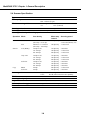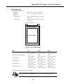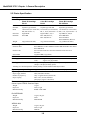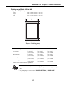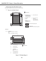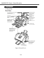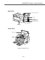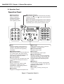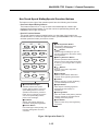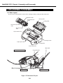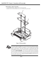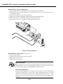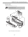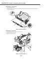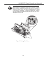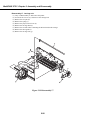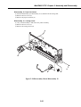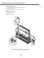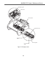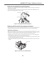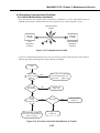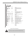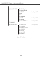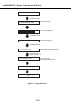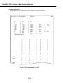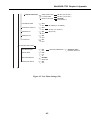
1
MultiPASS C755
SERVICE
MANUAL
Canon
I. MEANING OF MARKS
The marks used in this manual have the following meanings.
Mark
Meaning
States a precaution to be taken to prevent danger to personnel, damage to the product, or
damage to electronic components by discharge of static electricity. for example.
States a precaution to be taken to prevent damage to electronic components by
electrostatic discharge.
Informs you of fire-related cautions.
Informs you that the plug must be removed from the power outlet before starting an
operation.
Gives useful information to understand descriptions.
NOTE
Indicates sections to be read to obtain more detailed information.
REFERENCE
I
II. ABOUT THIS MANUAL
This manual is divided into five parts, and contains information required for servicing the product.
Each of the above parts is further divided into the following four chapters:
Chapter 1: General Description
This part explains product specifications and the how to service the unit safely. It is very important, so
please read it.
Chapter 2: Assembly and Disassembly
This part explains the assembly and disassembly of the product.
Chapter 3: Maintenance and Service
This part explains how to maintain the products for adjustment and troubleshooting and service operations
and service switches.
Chapter 4: Appendix
This part explains the informations of the optional products and user data flow.
• For more details of user operations and user reports, see the separate volume of USER'S
GUIDE.
• Greasing points is not given in this manual. See the illustrations in the separate volume of
REFERENCE PARTS CATALOG.
• Detailed description of each SSSW/parameter is not given in this manual except the new
SSSWs/parameters added to this model.
See G3 Facsimile Service Data Handbook (supplied separately) for details them.
• See the G3 Facsimile Error Code List (Rev.1, supplied separately) for details of the
error codes not shown in this manual.
II
III. REVISION HISTORY
REVISION
0
CONTENT
Original
III
IV. TABLE OF CONTENTS
Page
Chapter 1: General Description
1- 1
1. FEATURES
1- 1
1- 2
1.1 Overview
2. SPECIFICATIONS
1- 2
2.1 General Specification
1- 2
2.2 Communication Specification
1- 3
2.3 Color Communication Specification
1- 4
2.4 Scanner Specification
1- 6
2.5 Printer Specification
1- 9
2.6 Copy Specification
1 -10
2.7 Function
1 -12
3. OVERVIEW
1 -12
3.1 External View
1 -14
3.2 Operation Panel
1 -17
3.3 Consumables
1 -17
3.3.1 BJ cartridge and ink cartridge
1 -19
3.3.2 Print media
Chapter 2: Assembly and Disassembly
2- 1
1. ATTENTION TO BE PAID DURING ASSEMBLY/DISASSEMBLY
2- 1
1.1 Safety Cautions
2- 2
1.2 General Cautions
2- 3
1.3 Product-Inherent Cautions
2- 3
1.4 Action in the Event of Abnormality (All Clear)
2- 4
2. DISASSEMBLY/ASSEMBLY
2- 4
2.1 Parts Layout
2- 6
2.2 Disassembly Work-Flow
2- 7
2.3 Disassembly Procedure
Chapter 3: Maintenance & Service
3- 1
1. MAINTENANCE LIST
3- 1
1.1 Consumables
3- 1
1.2 Cleaning
3- 2
1.3 Periodic Inspection
3- 2
1.4 Periodic Replacement Parts
3- 2
1.5 Adjustment Items
3- 3
1.6 General Tools
3- 3
1.7 Special Tools
3- 4
2. HOW TO CLEAN PARTS
3- 4
2.1 Main Unit Outer Covers
3- 4
2.2 Separation Roller
IV
3- 4
2.3 Document Feed/Eject Roller
3- 4
2.4 Separation Guide
3- 4
2.5 Scanning Glass (Contact Sensor)
3- 4
2.6 White Sheet
3- 4
2.7 Printer Platen
3- 6
3. ADJUSTMENT
3- 6
3.1 CS LED Lights-on Duration Adjustment
3- 7
3.2 When Adjustment of the Print Head Position is Required
3- 9
3.3 When the Carriage Belt Tension Needs Adjustment
3- 9
3.4 When the ASF Gear Initial Position Adjustment is Required
3 -11
3.5 When the Head Gap Needs Adjustment
3 -14
4. TROUBLESHOOTING
3 -14
4.1 Troubleshooting Index
3 -16
4.2 Errors Shown on the Display
3 -16
4.2.1 User error message
3 -22
4.2.2 Error codes
3 -30
4.3 Errors not Shown on the Display
3 -30
4.3.1 General errors
3 -31
4.3.2 Printing problems
3 -33
4.3.3 Scanning problems
3 -35
4.4 Processing Communication Problems
3 -35
4.4.1 Initial identification of problems
3 -36
3 -39
4.4.2 Procedures for processing communication problems
5. COMMUNICATION SYSTEM OPERATIONS
3 -39
5.1 FAX/TEL Switching
3 -39
5.1.1 Settings
3 -39
5.1.2 Parameters
3 -40
5.2 Answering Machine Connection
3 -40
5.2.1 Settings
3 -40
5.2.2 Parameters
3 -40
5.3 Manual/Auto Reception Switching
3 -40
5.3.1 Settings
3 -40
5.3.2 Parameters
3 -41
5.4 Operations Where Other Machine Does not Have Color Communications Ability
3 -41
5.5 Conditions Necessary for Color Reception
3 -42
5.6 Specifications for Color Communications
3 -43
6. SERVICE SWITCHES
3 -43
6.1 Hardware Switches
3 -43
6.2 Service Data Setting
3 -43
6.2.1 Service data overview
3 -44
6.2.2 Service data registration/setting method
3 -45
6.2.3 Service data setting
3 -52
6.2.4 Explanation of service data
3 -53
6.2.5 New SSSWs/parameters added to this model
V
3 -57
7. TEST FUNCTIONS
3 -57
7.1 User Test Print Functions
3 -57
7.1.1 Nozzle check
3 -58
7.2 Service Test Functions
3 -58
7.2.1 Test mode overview
3 -59
7.2.2 Test mode flowchart
3 -61
7.2.3 D-RAM tests
3 -61
7.2.4 CS tests
3 -62
7.2.5 PRINT test
3 -64
7.2.6 Modem and NCU tests
3 -67
7.2.7 Faculty tests
3 -72
7.2.8 Printer test
3 -73
3 -73
8. SERVICE REPORT
8.1 Report Output Function
3 -73
8.1.1 User report output functions
3 -75
8.1.2 Service report output functions
3 -83
3 -83
9. WIRING DIAGRAM
9.1 Wiring Diagram
3 -84
10. BLOCK DIAGRAM
3 -84
10.1 Block Diagram
3 -85
10.2 Circuit Board Components
Chapter 4: Appendix
4- 1
1. USER DATA FLOW
4- 1
1.1 User Data Flow (by Operation Panel)
4- 4
1.2 User Data Flow (by MultiPASS Suite)
INDEX
VI
MultiPASS C755 Chapter 1: General Description
1. FEATURES
1.1 Overview
This product is a G3 transreceiving facsimile based on the ITU-T recommendations. It can be used in
telephone networks.
*: This mark indicates a new function.
Picture Quality Color Printer
High quality printing can be accomplished with the Canon Bubble Jet (BJ) method using the maximum
1440dpi × 720dpi resolution. Various kinds of media can be printed with the high speed of a maximum
8.7 pages per minute. The printing paper tray can hold up to 100 sheets of plain paper, 50 sheets of OHP
film, or 10 back print films or envelopes.
*Plain paper fax which can transmit/receive in color
Conforming to ITU-T recommendations, this fax is able to transmit/receive in color. Due to containing
extremely high-speed 33.6kbps modems, transmission time can be shortened. Pictures and photographs
can both be send and received clearly by UHQ(Ultra High quality), Canon’s vivid image processing
technology. Up to 20 letter- or A4- size sheets, or up to 10 legal-size sheets, can be set in the ADF. 12
one-touch dial entries and 100 speed dial entries can be registered, and group dial and broadcasting
transmission can also be done. When paper and ink run out, the data is saved to memory, so there is no
worry. When a external-phone is attached, fax communication and normal telephone reception are
possible due to DRPD service and FAX/TEL switching.
BJ Cartridge
Printing quality superior to photos is produced by use of BC-30 and BC-33/BC-34 photo BJ cartridges.
*Out-of-Ink Function
This machine has a function which detects when ink has run out. It also detects when the cartridges of
machines equipped with color communications are out of ink. The presence/absence of ink in the ink
chamber is detected by reflecting ink sensor.
Copy Function
This machine can be used as a 360dpi × 360 dpi high resolution full color copier. With a monochrome
document (including half-tone), up to 99 pages can be copied at one time at the speed of a maximum of 3
pages/minute.
Full Color & 256 Gradation Grayscale Scanner
Using graphics or OCR software which conforms to the TWAIN standard, full color and 256-gradation
grayscale images with a quality of 30dpi ~ 600 dpi can be read into a computer. Reading in can be done at
a resolution of 300dpi, and can be enhanced to 600dpi using the included MultiPASS Suite.
PC Fax
By connecting this machine to a computer, a fax can be transmitted from the included MultiPASS Suite
or from a Windows application, and a received image can be saved to the computer as-is without printing
it out.
1-1
MultiPASS C755 Chapter 1: General Description
2. SPECIFICATIONS
2.1 General Specification
Type
Body colour
Power source
Power consumption
Usage environment.
Operating noise
Dimensions (W × D × H)
Weight
Desktop
Art gray
98 ~ 132V AC, 48 ~ 62 Hz
Standby 6.0 W
Max. 44.9 W (when 100% black copy)
50.0°F ~ 90.5°F (10°C ~ 32.5°C), 20%~85% RH, 570 ~ 760
mmHg (760 ~ 1013 hPa)
Horizontal
±3° or less
Measured in accordance with ISO standards
Operating
:47 dB(A) or less
17.20" × 16.85" × 8.15" (437 mm × 428 × 207 mm)
(Not including Trays)
14.55 lbs (6.6 kg) Including trays
2.2 Communication Specification
Applicable lines
Applicable Services
Handset
Transmission method
Transmission control protocol
PSTN (Public Switched Telephone Network)
DRPD (Distinctive Ring Pattern Detection)
None
Half-duplex
ITU-T T30 binary protocol/ECM protocol/
ITU-T V.8 protocol/V.34 protocol/ECM protocol
Modulation method
G3 image signals
ITU-T V.27ter (2.4k, 4.8k bps)
ITU-T V.29 (7.2k, 9.6k bps)
ITU-T V.17 (TC7.2k, TC9.6k, 12k, 14.4k bps)
ITU-T V.34 (2.4k, 4.8k, 7.2k, 9.6k, 12k, 14.4k, 16.8k, 19.2k,
21.6k, 24k, 26.4k, 28.8k, 31.2k, 33.6k bps)
G3 procedure signals
ITU-T V.21 (No.2) (300bps)
ITU-T V.8 300bps
ITU-T V.34 600 bps, 1200 bps
(With automatic fallback function)
Coding
Black/white ITU-T T.4 Coding method (MH, MR)
ITU-T T.6 Coding method (MMR)
ITU-T T.82/T.85 Coding method (JBIG)
Color
ITU-T T.81 Coding method (JPEG)
Error correction
ITU-T T30 (ECM)
Canon express protocol (CEP)
None
1-2
MultiPASS C755 Chapter 1: General Description
Time required for transmission protocol
Protocol
Mode
G3 standard
V.8/V.34
Pre-message
Protocol *1
approx.18 sec.
approx.8 sec.
Post-message
Protocol *2
(between pages)
approx.4 sec.
approx.2 sec.
Post-message *3
(after pages)
approx.4 sec.
approx.2 sec.
*1 Time from when other facsimile is connected to the line until image transmission begins.
*2 Post-message (between pages): Time from after one document has been sent until
transmission of the next document starts if several pages are transmitted.
*3 Post-message (after last pages): Time from after image transmission is completed until
line is switched from facsimile to telephone.
Minimum transmission time
Transmission output level
Receive input level
Modem IC
10 msec (G3), 0 msec (G3, ECM)
From 0 to -15 dBm
From -3 to -43 dBm
FM336
2.3 Color Communication Specification
ITU-T recommendation
Scanning Document size
Printing paper size
Resolution
Picture element
Coding
Color space
Illuminant Data
Sub sample
ITU-T T.30 ANNEX E (JPEG Color Fax)
T.4 ANNEX E (JPEG Header)
T.42 (Color space for Color Fax)
T.81 (JPEG)
A4
A4
200×200 dpi
8 bit
JPEG
CIELAB
CIE Standard Illuminant D50
4:1:1 (=Lab)
1-3
MultiPASS C755 Chapter 1: General Description
2.4 Scanner Specification
Type
ADF capacity
Sheets
Max. 20 sheets (A4/Letter)
Max. 10 sheets (Legal)
Effective scanning width
Letter/Legal
8.42" (214 mm)
A4
8.19" (208 mm)
Scanning method
Contact sensor scanning method
Scanning resolution
600 × 600 dpi
Scanning line density & Scanning speed
Operation Mode
Line density
FAX
8 dot/mm × 3.85 line/mm
(203.2 dpi × 97.79 dpi)
8 dot/mm × 7.7 line/mm
(203.2 dpi × 195.58 dpi)
150 dpi or less
151~300 dpi
301~600 dpi
150 dpi or less
151~300 dpi
301~600 dpi
150 dpi or less
151~300 dpi
301~600 dpi
360 dpi
360 dpi
Standard
Fine
Scanner
Text (Binary)
Gray scale
Full color
Copy
B&W
Full color
Scanner gradations
TWAIN
Scanning density adjustment
Image modes
Halftone (fax and copy)
Prescan
Motor step
interval
150 dpi/step
Scanning speed
300 dpi/step
5 msec/line (Direct TX)
3.3 msec/line (Memory TX)
3.3 msec/line
150 dpi/step
300 dpi/step
600 dpi/step
150 dpi/step
300 dpi/step
600 dpi/step
150 dpi/step
300 dpi/step
600 dpi/step
600 dpi/step
600 dpi/step
5 msec/line
3.3 msec/line
3.3 msec/line
5 msec/line
3.3 msec/line
3.3 msec/line
9 msec/line
9 msec/line
9 msec/line
3.3 msec/line
9 msec/line
Grayscale; 8 bit, 256 gradations
Color;
R,G,B (8 bits each) full color capability
Yes
3 density level
Halftone (PHOTO mode)
64-gradation error diffusion system (UHQ)
Yes
1-4
MultiPASS C755 Chapter 1: General Description
Scanning range
Sheet dimensions (W × L)
Maximum
Minimum
Thickness
multiple pages:
8.50" × 39.3" (216 mm × 1000 mm)
3.5" × 1.75" (88.9 mm × 44.5 mm)
0.003" ~ 0.005" (0.08 mm ~ 0.13 mm)
75~90 g/m2
0.003" ~ 0.017" (0.08 mm ~ 0.43 mm)
75~340 g/m2
single page:
Document leading edge
3
1
4
SCANNING
DROP OUT RANGE
5
SCANNING RANGE
2
6
Document trailing edge
Figure 1-1 Scanning Range
Item
1 Effective scanning width
2 Effective scanning length
3 Left margin
4 Right margin
5 Top margin
6 Bottom margin
A4
8.09"~8.23"
(205.5~209 mm)
11.54"
(289~297 mm)
0.04" ±0.14"
(1.0 mm ±3.5 mm)
0.04" ±0.14"
(1.0 mm ±3.5 mm)
0.08" ±0.08"
(2.0 mm ±2.0 mm)
0.08" ±0.08"
(2.0 mm ±2.0 mm)
Letter
8.31"~8.46"
(211.0~215 mm)
10.84"
(271.4~279.4 mm)
0.04" ±0.14"
(1.0 mm ±3.5 mm)
0.04" ±0.14"
(1.0 mm ±3.5 mm)
0.08" ±0.08"
(2.0 mm ±2.0 mm)
0.08" ±0.08"
(2.0 mm ±2.0 mm)
Legal
8.31"~8.46"
(211.0~215 mm)
13.84"
(347.6~355.6 mm)
0.04" ±0.14"
(1.0 mm ±3.5 mm)
0.04" ±0.14"
(1.0 mm ±3.5 mm)
0.08" ±0.08"
(2.0 mm ±2.0 mm)
0.08" ±0.08"
(2.0 mm ±2.0 mm)
Units are inches with mm shown in parentheses.
Document scanning width “A4/LTR” is set in service data #1 SSSW SW06, bit4.
NOTE
1-5
MultiPASS C755 Chapter 1: General Description
2.5 Printer Specification
Printing method
Bubble-jet ink on-demand
BJ Cartridge
Black BJ Cartridge
Color BJ Cartridge
BC-30
BC-33
Product code F45-1471
F45-1491
Structure
Separate type ink tank
Separate type ink tank
Head
160 nozzles (in a vertical line) 192 nozzles (in a vertical line)
Bk (160 nozzles × 1)
Bk, C, M, Y (48 nozzles × 4)
Ink colors
Pigment Bk
Pigment Bk, C, M, Y
Ink tanks
BCI-3BK
BCI-3BK, BCI-3C,
BCI-3M, BCI-3Y
Photo BJ Cartridge
BC-34Photo
F45-1511
Separate type ink tank
192 nozzles (in a vertical line)
Bk, C, M, Y (48 nozzles × 4)
Dye PBk, PC, PM, Y
BCI-3BK Photo
BCI-3PC Photo
BCI-3PM Photo, BCI-3Y
75g (without ink tanks)
Weight
60g (without ink tank)
72g (without ink tanks)
Ink Cartridge
Products name
BCI-3BK/BCI-3C/BCI-3M/BCI-3Y/BCI-3BK Photo/BCI-3PC Photo/
BCI-3PM Photo
Product code
F47-2171/F47-2181/F47-2191/F47-2201/F47-2231/F47-2211/
F47-2221
Ink contains
23g (BCI-3BK)/11g (others)
Ink detection
Optical LOW-Ink sense
Printing speed
Black
Approx. 8.7 pages/minute (in case of character print)
Color
Approx. 4.6 page/minute
Printing resolution
360 dpi × 360 dpi (Normal print), 1440 dpi × 720 dpi (Printer mode)
180 dpi × 180 dpi (Economy print*)
*Printing in a checkered pattern without printing vertical and horizontal adjacent dots.
Paper output tray stacking
Approx. 50 sheets (when using the recommended paper)
Paper tray
Paper supply method
ASF (Auto Sheet Feeder)
Number of paper tray
1tray : Legal/Letter/A4 (Universal )
Paper capacity
Max. 0.40" (10 mm) thickness
plain paper (Approx. 100 sheets)
Recommended paper
Canon Copier LTR/LGL Premium Paper
Weight
75 g/m2
Paper size
Letter, Legal
Manufactured by
BOISE CASCADE
PLOVER BOND
Weight
Paper size
Manufactured by
75 g/m2, 90 g/m2
Letter
FOX RIVER
XEROX 4024
Weight
Paper size
Manufactured by
75 g/m2, 90 g/m2
Letter, Legal
XEROX
1-6
MultiPASS C755 Chapter 1: General Description
Printing range (Black & White FAX)
Paper dimensions (W × L)
Letter
Legal
A4
8.50" × 10.98" (216 mm × 279 mm)
8.50" × 14.02" (216 mm × 356 mm)
8.27" × 11.69" (210 mm × 297 mm)
Paper leading edge
2
1
3
PRINTING DROP OUT RANGE
4
PRINTING RANGE
5
Paper trailing edge
Figure 1-2 Printing Range
Item
1 Effective printing width
A4
8.00"
(203.2 mm)
2 Left margin
0.13"±0.06"
(3.4±1.5 mm)
3 Right margin
0.13"±0.06"
(3.4±1.5 mm)
4 Top margin
0.12"±0.06"
(3.0±1.5 mm)
5 Bottom margin
0.20"±0.12"
(5.0±3.0 mm)
Units are inches with mm shown in parentheses.
NOTE
Letter
8.00"
(203.2 mm)
0.25"±0.06"
(6.4±1.5 mm)
0.25"±0.06"
(6.4±1.5 mm)
0.12"±0.06"
(3.0±1.5 mm)
0.20"±0.12"
(5.0±3.0 mm)
Legal
8.00"
(203.2 mm)
0.25"±0.06"
(6.4±1.5 mm)
0.25"±0.06"
(6.4±1.5 mm)
0.12"±0.06"
(3.0±1.5 mm)
0.20"±0.12"
(5.0±3.0 mm)
• The header and footer are printed in the printing range.
• The shaded area is included in the left and right margin errors of the paper trailing
edge.
• The printing range is set in user data “PRINTER SETTINGS”, “PAPER SIZE”.
1-7
MultiPASS C755 Chapter 1: General Description
Printing range (Color FAX & Printer mode)
Plain paper and Special media (Color FAX & Printer mode)
W ✕ L = Min. 7.17 ✕ 1012 inch(182 ✕ 257 mm)
Max. 8.5 ✕ 14.0 inch(216 ✕ 356 mm)
W
Feed direction
c
d
a
e
L
a = (Plain paper , etc.)
0.12 inch/3.0 mm
(Fabric sheet only)
1.5 inch/38.1 mm
e = 1.26 inch/32.0 mm
b = 0.20 inch
5 mm
f = 0.91 inch/23.0 mm
(BC-30)
1.02 inch/26.0 mm
(BC-33/34 Photo)
c = (A4)
0.13 inch/3.4 mm
(LTR, LGL)
0.25 inch/6.4 mm
: Recommended printing area
f
b
: Printable area
(contains recomended printing area)
Envelopes
W ✕ L = (COM #10)
9.48 ✕ 4.17 inch(241 ✕ 106 mm)
(DL)
8.66 ✕ 4.33 inch(220 ✕ 110 mm)
W
d
c
a
e
L
f
b
a=
0.12 inch/3.0 mm
b=
0.20 inch/5 mm
c=
0.27 inch/6.4 mm
d=
(COM #10)
1.24 inch/31.4 mm
(DL)
0.41 inch/10.4 mm
e=
1.26 inch/32.0 mm
f=
0.93 inch/23.5 mm
Feed direction
Figure 1-3 Printing Range (1)
1-8
MultiPASS C755 Chapter 1: General Description
c
Banner paper
a
1
2
3
4
5
6
b
Max.6 folds (To be cut at the edge of the 7th fold)
d
: Recommended print area
: Printable area
a=0.13inch / 3.4mm
b=0.13inch / 3.4mm
c=0.12inch / 3.0mm
d=1.26inch / 32mm
Figure 1-4 Printing Range (2)
2.6 Copy Specification
Color copy
Multiple copy
Copy mode
Yes
99 copies (Black & white mode only)
Black & white
Color
TEXT, PHOTO
PLAIN PAPER, HI RES PAPER, COLOR DRAFT,
COLOR SNAPSHOT
Copy resolution
360 dpi × 360 dpi (direct copy)
8 dot/mm × 7.7 line/mm (memory copy)
Color
360 dpi × 360 dpi
(PLAIN PAPER, HI RES PAPER,
COLOR SNAPSHOT)
180 dpi × 180 dpi (COLOR DRAFT)
Printing
360 dpi × 360 dpi
Copy magnification ratio 100%, 90%, 80%, 70%
150%, 200% (COLOR SNAP SHOT)
Scanning
Black & white
1-9
MultiPASS C755 Chapter 1: General Description
2.7 Function
Dialling
Manual dialling
Auto dialing
Group dial
Redial
Transmission
Broadcast transmission
Numeric button
Max. 120 digits
One-touch:12, Coded speed:100, Numeric button:1
Max.111 locations
Numeric button redial function (Max. 120 digits)
Max. 113 locations (One-touch:12, Coded speed:100, Numeric
button:1)
Delayed transmission
Yes (PC Assisted) Max. 30 reservation
Confidential Tx/Rx
None
Relay broadcasting originating None
Relay broadcasting
None
Reception
Dual Access
Yes
FAX/TEL switching
Yes
Method
CNG, detection
Message
None
Pseudo CI
None
Pseudo ring
Yes
Pseudo ringback tone
Yes
Reduction settings for reception
Automatic reduction of reception images
Built-in Answering machine
Answering machine connection
Remote reception
Memory lock reception
Reception printing in reverse order
Polling
Polling transmission
Polling reception
Yes
Yes (100% ~ 70%)
None
Yes (Telephone answering priority type)
Yes (Remote ID method)
None
None
None
None
1-10
MultiPASS C755 Chapter 1: General Description
Others
Closed network
None
Direct mail prevention
None
Reception printing in reverse order
None
Memory box
None
Memory backup
Backup contents
Dial registration data, User data, Service data, Time
Backup IC
273 kbit SRAM for control
Backup device
Lithium battery 3.0V DC/220 mAh
Battery life
Approx. 5 years
Image data backup
None
Image Memory
Approx. 6.67 MB
Activity management
Yes
a) User report
Activity management report (Every 20 transactions : always transmission and reception together)
Activity report (sending/receiving)
One-touch speed dialling list
Coded speed dialling list
Group dialling list
Memory clear list
User’s data list
Document memory list
Multi activity report
b) Service report
System data list
System dump list
Error list
Transmitting terminal identification
Time
Management data
Precision
Display
Completion stamp
Program button
Hook button
Telephone exchange function
Speaker phone
Demo print function
HELP function
Yes
Year/month/date/day/hour/minute (24 hour display)
±90 sec per month
1 row × 16 digits
None
None
Yes
None
None
None
None
1-11
MultiPASS C755 Chapter 1: General Description
3. OVERVIEW
3.1 External View
Front View
DOCUMENT SUPPORT
Holds documents as
they feed into the ADF.
ADF (AUTOMATIC DOCUMENT FEEDER)
and PRINTER COVER
Holds documents to be scanned.
PAPER REST
Supports print media
stacked in the multipurpose tray.
PAPER GUIDE
Keeps print media in position.
Adjust to the width of the print
media.
MULTI-PURPOSE TRAY
Holds plain paper and
other print media.
DOCUMENT GUIDES
Keep the document in
position when being
scanned. Adjust to the
width of the document.
HANDLE
Opens the printer cover.
OPERATION PANEL
Controls the MultiPASS.
DOCUMENT TRAY
When open, holds scanned
documents as they exit the
MultiPASS. When closed,
serves as a cover for the
operation panel.
PAPER THICKNESS LEVER
Adjusts the gap between the
print head and the print
media to suit the print
media’s thickness.
OUTPUT TRAY
Holds printed pages as
they exit the MultiPASS.
Figure 1-5 External View (1)
1-12
MultiPASS C755 Chapter 1: General Description
Back View
PARALLEL INTERFACE PORT
USB PORT
TELEPHONE/
ANSWERING MACHINE/
DATA MODEM JACK
TELEPHONE LINE JACK
POWER CORD
CONNECTOR
Inside View
PRINTER COVER
CARTRIDGE
HOLDER
Figure 1-6 External View (2)
1-13
MultiPASS C755 Chapter 1: General Description
3.2 Operation Panel
Operation Panel
■ Document Feed Lever
Sets the ADF to (automatic document feed) for feeding
multipage documents, or to (manual document feed) for
feeding single sheets.
■ Numeric Buttons
Enter numbers when
dialing or registering
fax/telephone numbers.
Also enter characters
when registering names.
ABC
01
DEF
2
1
■ One-Touch Speed Dialing/Special Function Buttons
Dial fax/telephone numbers pre-registered for one-touch
speed dialing. Also used to perform special functions.
3
04
Alarm
GHI
JKL
4
MNO
5
TUV
PRS
7
6
Redial /Pause Coded Dial
Color / B&W
Receive Mode
Copy
07
0
06
Space
+
09
08
Report
9
10
Image Quality
Stop
Hook
OPER
03
05
Memory Reference
WXY
8
02
Data Registration
SYMBOLS
Start
11
12
Cleaning
Clear
Function
Set
Resume
#
Tone
■ LCD
Displays messages and prompts during
operation. Also displays selections, text,
numbers, and names when registering
information.
■ Redial/Pause Button
Redials the last number that was dialed with
the numeric buttons. Also enters pauses
between or after the fax/telephone number
when dialing or registering numbers.
■ Coded Dial Button
Press this button and a two-digit code to dial
a pre-registered fax/telephone number or
group.
■ Color/B&W Button
Sets the unit for color or black & white
transmission or copying. For color
transmission or color copying, press this
button to turn on its light.
■ Hook Button
Engages or disengages the telephone line.
■ Alarm Light
Flashes when an error occurs, or when the
MultiPASS is out of paper or ink.
■ Receive Mode Button
Selects the receive mode.
■ Copy Button
Sets the MultiPASS to make copies.
■ Image Quality Button
Selects the resolution setting the MultiPASS
uses for the document you are sending. Also
selects the image quality setting (resolution
and paper type) for the document you are
copying.
■ Stop Button
Cancels sending, receiving, registering data,
copying and other operations, and returns the
MultiPASS to standby mode.
■ Start Button
Starts sending, receiving, scanning, and
copying.
Figure 1-7 Operation Panel (1)
1-14
MultiPASS C755 Chapter 1: General Description
One-Touch Speed Dialing/Special Function Buttons
The buttons on the right of the operation panel have the following two functions:
• One-Touch Speed Dialing Buttons
The buttons marked 01 to 12 can be used to dial fax/telephone numbers preregistered under these buttons. To use the one-touch speed dialing buttons, the
Function button’s light must be off.
• Special Function Buttons
The special function buttons (marked under or to the sides of the buttons) are
described below. To access the special functions, press Function to turn on its light
and then press the button you wish to access.
01
02
■ Data Registration Button
Accesses the different menus for
customizing your MultiPASS.
■ , Buttons
Scroll through the settings so you can
see other selections in the menus during
data registration.
■ Memory Reference Button
Performs operations with documents
stored in memory. Also prints documents
in memory you no longer want to upload
to your PC.
■ , Buttons
Move the cursor left or right when
registering data.
■ Space Button
Enters a space between letters and
numbers when registering information.
■ + Button
Enters a plus sign (+) when registering
your unit fax/telephone number.
■ Report Button
Prints reports containing registered
information and information on
transactions.
03
Data Registration
04
05
Memory Reference
07
06
Space
+
08
09
11
12
Report
10
Cleaning
Clear
Function
Set
Resume
■ Function Button/Light
Switches between the special
function buttons and the one-touch
speed dialing buttons. To use the
special function buttons, press this
button to turn on its light. To use the
one-touch speed dialing buttons,
press to turn off its light.
■ Cleaning Button
Prints the nozzle check pattern, performs
cleaning operations, and aligns the BJ
cartridge print head position.
■ Clear Button
Clears an entire entry when registering
information.
■ Set Button
Selects and registers settings or
information during data registration.
■ Resume Button
Form-feeds paper when printing, and
resumes printing after an error is
corrected.
Figure 1-8 Operation Panel (2)
1-15
MultiPASS C755 Chapter 1: General Description
Guidelines for Entering Numbers, Letters,
and Symbols
When you come to a step that requires you to enter a name or number, refer to the
table below to determine which numeric button to press for the character you want.
Button
Letters (:A)
Numbers (:1)
1
1
ABC
2
ABCabc
2
3
DEFdef
3
4
GHIghi
4
5
JKLjkl
5
MNOmno
6
7
PQRSpqrs
7
8
TUVtuv
8
WXYZwxyz
9
DEF
GHI
JKL
MNO
6
PRS
TUV
WXY
9
OPER
0
0
SYMBOLS
#
Letter input (:A)
Number input (:1)
Tone
If you pause for more than 60 seconds between entering characters, the unit will
automatically return to standby mode.
Figure 1-9 Operation Panel (3)
1-16
MultiPASS C755 Chapter 1: General Description
3.3 Consumables
3.3.1 BJ cartridge and ink cartridge
BJ Cartridges and BJ Tanks
A BJ cartridge is made up of a “holder” that contains the print head unit, and different
color BJ ink tanks that are placed inside the “holder.” You can replace individual BJ
tanks as they run out.
Canon offers several BJ cartridges for use with the MultiPASS.
■ Color BJ Cartridge (Either one included with your MultiPASS)
Prints in color and monochrome. It contains four BJ tanks: Black, cyan, magenta, and yellow.
BC-33 Color BJ Cartridge*
-or-
BC-33e Color BJ Cartridge**
Ink
Ink
BCI-3 Tank
BK
BCI-3 Tank
BK
Ink
BC Tank
I-3C
Blac
k
de
PUSH
in Jap
k
Cyan
Ink
BC Tan
I-3
Mag
enta
an
Ma
de
in Jap
PUSH
Yello
w
Ink Tank
Ink Tank
Ink Tank
Ink Tank
BCI-3BK
BCI-3C
BCI-3M
BCI-3Y
Ma
de
PUSH
in Jap
de
PUSH
in Jap
Yello
w
Ma
de
PUSH
de
in Jap
PUSH
in Jap
Ma
de
in Jap
PUSH
Cyan
Magenta
Ink Tank
Ink Tank
Ink Tank
BCI-3C
BCI-3M
BCI-3Y
Black
Cyan
Magenta
Yellow
an
an
Black
Ink Tank
BCI-3BK
an
an
Ma
Ink
BC Tan
I-3
enta
de
PUSH
in Jap
Ink
BC Tank
I-3M
Mag
an
Ma
an
Ma
Ink
BC Tank
I-3C
Blac
Ink
BC Tank
I-3M
Cyan
Ma
an
Yellow
BLACK BJ TANK
(BCI-3BK or BCI-3eBK)
BLACK BJ TANK
(BCI-3eBK)
CYAN BJ TANK
(BCI-3C or BCI-3eC)
CYAN BJ TANK
(BCI-3eC)
MAGENTA BJ TANK
(BCI-3M or BCI-3eM)
MAGENTA BJ TANK
(BCI-3eM)
YELLOW BJ TANK
(BCI-3Y or BCI-3eY)
YELLOW BJ TANK
(BCI-3eY)
■ Photo BJ Cartridge (Sold separately)
Prints photo-realistic images in color. It contains four BJ tanks: Photo black, photo cyan,
photo magenta, and yellow.
BC-34 Photo BJ Cartridge*
-or-
BC-34e Photo BJ Cartridge**
Ink
BCI Tank
-3PBK
Photo
Ink
BCI Tank
-3PBK
Photo
Ink
BC Tank
I-3PC
Photo
Ph
Blac oto
k
Ma
Ph
Cyanoto
de
PUSH
in Jap
Ma
de
PUSH
in Jap
I-3
Ma
de
PUSH
in Jap
Ink Tank
BCI-3PBK
Photo
Ink Tank
Ink Tank
BCI-3PC BCI-3PM
Photo
Photo
Ink Tank
Ma
de
PUSH
BCI-3Y
in Jap
MagPhoto
enta
an
Ma
de
PUSH
an
Ma
Ph
Cyanoto
n
Yello
w
an
Ink
BC Tank
I-3PC
Photo
Ph
Blac oto
k
InkTa
BC
MagPhoto
enta
an
Ink
BC Tank
I-3
Photo PM
in Jap
PUSH
in Jap
Ma
de
in Jap
Ma
de
PUSH
Photo
Cyan
Photo
Magenta
Ink Tank
BCI-3PBK
Photo
Ink Tank
Ink Tank
BCI-3PC BCI-3PM
Photo
Photo
Photo
Cyan
Photo
Magenta
Ink Tank
BCI-3Y
an
an
Photo
Black
Ink
BC Tan
I-3
Yello
w
an
PUSH
de
Ink
BC Tank
I-3
Photo PM
in Jap
an
Photo
Black
Yellow
PHOTO BLACK BJ TANK
(BCI-3PBK Photo or BCI-3ePBK Photo)
PHOTO BLACK BJ TANK
(BCI-3ePBK Photo)
PHOTO CYAN BJ TANK
(BCI-3PC Photo or BCI-3ePC Photo)
PHOTO CYAN BJ TANK
(BCI-3ePC Photo)
PHOTO MAGENTA BJ TANK
(BCI-3PM Photo or BCI-3ePM Photo)
PHOTO MAGENTA BJ TANK
(BCI-3ePM Photo)
YELLOW BJ TANK
(BCI-3Y or BCI-3eY)
YELLOW BJ TANK
(BCI-3eY)
Yellow
* You can use both BCI-3 and BCI-3e BJ tanks in this BJ cartridge. However, we recommend you use the
same model for all four BJ tanks.
** Use only BCI-3e BJ tanks in this BJ cartridge.
Figure 1-10 Consumables (1)
1-17
MultiPASS C755 Chapter 1: General Description
■ Black BJ Cartridge (Sold separately)
Prints in monochrome. It contains one black BJ tank.
BC-30 Black BJ Cartridge*
-or-
BC-30e Black BJ Cartridge**
Ink
Ink
BCI-3 Tank
BK
BCI-3 Tank
BK
Blac
Blac
k
k
Ink Tank
Ma
de
PUSH
BCI-3BK
in Jap
an
Ink Tank
Ma
de
PUSH
in Jap
an
Black
BLACK BJ TANK
(BCI-3BK or BCI-3eBK)
BCI-3BK
Black
BLACK BJ TANK
(BCI-3eBK)
• To help ensure the maximum life of your BJ cartridges, always follow the guidelines for
cartridge maintenance.
• For optimum printing results and to avoid printing problems, Canon recommends that you
only use the Canon BJ cartridges and tanks mentioned in this guide.
Figure 1-11 Consumables (2)
1-18
MultiPASS C755 Chapter 1: General Description
3.3.2 Print media
■ Plain Paper
The MultiPASS supports letter-, legal-, and A4-size paper in portrait orientation. You can
use regular copier paper, cotton bond paper, and typical letterhead. Your unit does not
require special ink jet paper, and produces letter quality print on most plain paper. Always
use paper without curls, folds, staples, or damaged edges. Copier paper has a preferred
side for printing. Look at the label on the package to see which side to print on.
■ Envelopes
The MultiPASS can print on U.S. Commercial No. 10 envelopes and European DL
envelopes.
The following envelopes are not recommended because they may cause jams or
smears, resulting in damage to your unit:
• Envelopes with windows, holes, perforations, cutouts, and double flaps.
• Envelopes made with special coated paper or deeply embossed paper.
• Envelopes with peel-off sealing strips.
• Envelopes with letters enclosed.
You may be able to stack envelopes of other sizes in the multi-purpose tray. However,
Canon cannot guarantee consistent performance on envelope sizes other than U.S.
Commercial No. 10 and European DL.
■ Glossy Photo Paper GP-301
Canon Glossy Photo Paper GP-301 is a high gloss, thick paper that produces the look
and feel of a photograph. Use this paper with the Photo BJ cartridge to print photorealistic images.
■ Banner Paper
Canon Banner Paper is specifically designed for printing one continuous sheet in a
banner format. The connected sheets are divided by perforations and you can print
from two to six sheets at a time. Canon Banner Paper is specially designed for use with
Bubble Jet printers and produces bright and vivid color images.
■ High Resolution Paper HR-101S/HR-101N*
Canon High Resolution Paper HR-101S/HR-101N is designed to produce nearphotographic quality print output with sharp and vivid graphics. For best results, use this
paper with the Photo BJ cartridge.
* The Canon High Resolution Paper HR-101N will be released in the near future.
Figure 1-12 Print Media (1)
1-19
MultiPASS C755 Chapter 1: General Description
■ Bubble Jet Paper LC-301
Canon Bubble Jet Paper LC-301 has been developed for high quality printing with
minimal or no smearing or running when in contact with water or damp surfaces. This
specially coated paper produces bright and vivid colors and stands up to normal office
highlighters, unlike images printed on other paper.
■ Back Print Film BF-102
Canon Back Print Film BF-102 has been specially developed for Bubble Jet printers.
This unique mylar-based translucent sheet is designed to deliver sharp, brilliant, highintensity color images suitable for business presentations, design work, or professional
reports. Back print film is printed on the back (non-glossy) side of the film in mirror
image and then viewed from the front (glossy) side using a backlit device, such as a
light box.
■ High Gloss Photo Film HG-201
Canon High Gloss Photo Film HG-201 features a bright white finish that lends striking
visual power to charts, graphs, and photographic images. It creates a sharper and more
vivid color output than is possible with coated paper. Use of this film gives your
presentation materials and graphics a professional look. This film provides the best
color print quality for the Color BJ cartridge.
■ Transparencies CF-102
Canon Transparencies CF-102 produce excellent contrast, sharpness, and color,
creating crisp and professional overhead presentations.
Do not use normal transparencies in the MultiPASS as they do not absorb ink and may
cause ink to run.
■ Glossy Photo Cards FM-101
Canon Glossy Photo Cards FM-101, made from the same stock as Glossy Photo
Paper, allow you to print images over the entire area of the card. Print the image so that
it extends beyond the perforations and then trim off the unwanted white margins.
Figure 1-13 Print Media (2)
1-20
MultiPASS C755 Chapter 2: Assembly and Disassembly
1. ATTENTION TO BE PAID DURING ASSEMBLY/ DISASSEMBLY
1.1 Safety Cautions
Electrical shock
In order to prevent any risk of electrical shock, always be sure to check that the power cord and modular
jack have been removed. Also, remove all cables connecting to the computer. When conducting service
that requires the main unit to be powered on, be sure to wear some kind of earthing, such as a wrist strap,
etc. Otherwise, there is a danger of conduction and electrical shock.
Parts which are generally likely to cause electrical shock are as follows.
• Power supply unit primary (supplied with AC voltage)
• Telephone line primary
• LBP engine high voltage contacts (for high voltage during developing and transfer)
High temperature
In order to prevent burns during disassembly, allow at least ten minutes, after the power has been switched
off, for the high temperature components to cool down.
General high temperature components are as follows.
• Motors
• Power supply unit
• Elements on driver ICs, etc., on PCBs (in particular, ICs with heatsinks)
• BJ cartridge aluminium plate (for BJ cartridge engine models)
• Fixing unit and peripheral covers (for LBP engines)
Fire
It is dangerous to throw lithium batteries and parts and components containing flammable substances, such
as cartridges, etc., into fire. Such parts and components must be disposed of in accordance with local laws
and regulations.
Ignition
When using solvents such as alcohol, etc., while conducting service, there is a danger of fire igniting from
heat from internal circuitry and from sparks. Before using any such solvents, be sure to switch off the
power and allow time for high temperature parts to cool down. Make sure that there is sufficient
ventilation when working with solvents.
Movable parts
In order to prevent accidents with movable parts, be sure to remove the power cable when conducting
service that requires disassembly. Also, take care that personal accessories and hair, etc., are not caught in
any moving parts.
2-1
MultiPASS C755 Chapter 2: Assembly and Disassembly
1.2 General Cautions
Damage due to electrostatic discharge
This machine contains contact sensors and printed circuit boards that use ROMs, RAMs, custom chips and
other electronic components that are vulnerable to damage by electrostatic discharge.
Be careful to avoid any damage from electrostatic discharge when conducting service that requires
disassembly.
Static electricity warning
Electrostatic discharge can destroy electronic components and alter electrical
characteristics. Plastic tools and even your hands, if they are not earthed, contain
sufficient static electricity to damage electronic components.
The following materials may be used as countermeasures against electrostatic discharge:
• an earthed, conductive mat,
• an earthed wrist-strap,
• crocodile clips for the purpose of grounding metallic parts of the main unit.
For service conducted on the user’s premises, etc., where such countermeasure materials are not available,
the following countermeasures may be employed.
• Use anti-static bags for the storage and carrying of PCBs and electrical elements.
• Avoid silk and polyester clothing and leather soled shoes, favouring instead cotton clothes and rubber
soled shoes.
• Avoid working in a carpeted area.
• Before beginning the work, touch the grounded earth terminals of the main unit in order to discharge any
static electricity.
• Use a wrist-strap and earth the metal parts of the main unit.
• PCBs and electrical elements must lifted around the edges and their terminals must not be touched.
Caution against electrical shock while working with power on
In cases where service must be carried out with power on, via a connected power cable,
be sure to wear an anti-static wrist-strap or other earth, in order to prevent an electrical
path being created through your body.
Application of grease
Grease must not be applied to any parts that are not so designated. If grease comes into contact with the
rubber cap of the purge unit or wire, the BJ cartridge nozzle may become blocked and the cartridge
rendered unusable. Also, never use any other than the specified type of grease. Otherwise, plastic parts
and rubber parts may melt or be otherwise deformed.
Attaching and removing cables
Attaching and removing cables with the power still on may cause breakdowns and should be avoided. In
particular, flat cables are likely to cause short circuits. When attaching or removing cables, always be sure
to turn the power off.
2-2
MultiPASS C755 Chapter 2: Assembly and Disassembly
1.3 Product-Inherent Cautions
Prevention of ink-soiling
Be careful when handling the BJ ink cartridge nozzle, the ink pad, head cap, head wiper and waste ink pad.
Residual ink may soil the main unit, working surfaces, your hands and clothes, etc. The ink is watersoluble, but because it contains pigments, it will not wash out of clothes.
The ink does not contain any substances that are harmful to humans, but does contain organic solvents
(isopropyl alcohol 67-63-0, diethylene glycol 111-46-6, glycerin 56-81-5 and ethylene glycol 107-21-1). If
the ink should accidentally get into someone’s eyes, rinse the affected eye with plenty of clean water and
seek medical attention. If a large quantity of ink is accidentally swallowed, seek medical advice
immediately. In such a case, let the doctor know exactly what is written on the BJ cartridge label.
Conductivity of the ink
The ink used in the BJ cartridge is conductive. This means that, if the ink leaks, mechanical parts should be
wiped with a dampened paper towel or similar and electrical circuits wiped with tissue paper so that all ink
is removed from below the IC chips.
If power is switched on while ink is leaking on the electrical circuits, the circuitry may short out and be
damaged. If ink is leaking, the power must be switched off.
1.4 Action in the Event of Abnormality (All Clear)
In the event of extreme noise or shock, etc., in very rare cases, the display may go out, and all the keys
become inoperable. In that case, perform an All Clear. This operation returns all values and settings to
their default settings. However, as all settings, such as received images and user data, service data, etc.,
will be re-initialised, be sure to note down any settings that you will need to re-enter later.
Function
Selects
ALL
Data Registration
ALL
Selects
#8 CLEAR
#
Set
#8 CLEAR
Execute All clear
Set
Standby
Figure 2-1 All Clear Operation
While waiting to return to the ready state after executing “All clear”, please do not press
the Stop button. Doing so may cause a malfunction afterwards.
2-3
MultiPASS C755 Chapter 2: Assembly and Disassembly
2. DISASSEMBLY/ASSEMBLY
2.1 Parts Layout
The parts layout of this machine consists of the scanning assembly, printing assembly and printer.
Separation roller
Document feed
motor
Pick up roller
Lifting plate
Document eject
roller
Document feed
roller
Paper feed motor
Carriage motor
Paper eject roller
Carriage belt
Paper feed roller
Paper path
Document path
Document feed section
Printer section
Paper feed section
Figure 2-2 Mechanical Layout
2-4
MultiPASS C755 Chapter 2: Assembly and Disassembly
The electrical parts are laid out as follows.
• SCNT board ........................ system control
• PCNT board ........................ printer control
• NCU board .......................... interface with telephone line
• Power supply unit ............... supplies power to the units and assemblies
• OPCNT board ..................... detects keyboard operation and displays machine information
• 7 sensors ............................. detect unit and assembly statuses
Cover sensor:
Detects the state of
printer cover.
Pickup roller sensor:
Detects the state of
pickup roller.
Paper edge sensor:
Detects the state of paper
feeding and delivery.
Ink detect sensor:
Detects that there is no
ink in the ink chamber
(Reflection-type sensor).
Home position sensor:
Detects the carriage position
and purge unit status.
Document edge sensor:
Detects the trailing edge
of the document.
Document sensor:
Detects whether or not
a document is set.
PCNT board
OPCNT board
Power supply unit
NCU board
SCNT board
Figure 2-3 Electrical Layout
2-5
MultiPASS C755 Chapter 2: Assembly and Disassembly
2.2 Disassembly Work-Flow
The work-flow for the disassembly of the main units is as follows. In order to replace parts, you need to
confirm which parts have to be removed. Numbers in parenthese indicate the disassembly number.
Main unit
Upper cover / Printer cover (1)
Replace the ROM (22)
PCNT board (13)
Scanner & Operation panel (2)
Operation panel (7)
Separation guide (8)
Separation roller (11)
White sheet unit (9)
Document feed motor (12)
Contact sensor (10)
SCNT/NCU board (3)
Print ASS'Y (4)
Power suplly unit (5)
Waste ink absorber (6)
Purge unit (16)
Paper feed motor (19)
Carriage unit (17)
Carriage motor (18)
ASF unit (14)
Pick-up roller (15)
Ink sensor (20)
Spur unit (21)
Figure 2-4 Disassembly Work-Flow
2-6
MultiPASS C755 Chapter 2: Assembly and Disassembly
2.3 Disassembly Procedure
Disassembly 1. Upper covers/printer covers
(1) Remove the three screws (a).
(2) Remove the two tabs (b), then remove the upper cover (c), and the printer cover (d).
a
d
c
b
Figure 2-5 Disassembly 1
To remove the upper cover, insert the tool into the two holes shown in the diagram and
prise loose the tabs. The front part of the cover is fastened with tabs, so it needs to be
pulled forward and then lifted up. When attaching the cover, fit the tabs in first.
NOTE
2-7
MultiPASS C755 Chapter 2: Assembly and Disassembly
Disassembly 2. Scanning assembly
(1) Perform disassembly 1.
(2) Remove the three cables (e), connected to the SCNT board at the left side of the main unit. Also, remove
the cables (f), connecting the SCNT board and the PCNT board. Then, remove the two cables (j), from
the carriage motor and the ink sensor, and remove the cable guide (c). When you remove the cable
guide, prise loose the tabs (d).
(3) Remove the two screws (g).
(4) Remove the two screws (a), and then take off the ground plate (b).
(5) Remove the stopper (h), and then remove the control panel and ADF upper assembly.
(6) Remove the two screws (i), and remove the ADF lower assembly.
e
g
D
e
B
1
C
h
g
A
a
i
a
e
b
f
A
B
d
c
j
E
D
C
Figure 2-6 Disassembly 2
2-8
E
MultiPASS C755 Chapter 2: Assembly and Disassembly
Disassembly 3. SCNT board/NCU board
The SCNT board and NCU board can be replaced without removing the scanning
assembly.
NOTE
SCNT board
(1) Perform Disassembly 1 and Disassembly 2 (3).
(2) Remove the two screws (a), and then take off the whole plate assembly.
(3) Remove the three cables connected to the SCNT board.
(4) Remove the four screws (b), and remove the SCNT board (c).
For details on ROM replacement, see page 2-23, Disassembly 22.
replacement.
REFERENCE
NCU board
(1) Perform Disassembly 1 and Disassembly 2 (3).
(2) Remove the two screws (a), and then take off the whole plate assembly.
(3) Remove the three cables connected to the NCU board.
(4) Remove the three screws (d), and remove the NCU board (e).
a
a
e
d
b
c
b
Figure 2-7 Disassembly 3
2-9
ROM
MultiPASS C755 Chapter 2: Assembly and Disassembly
Caution when replacing SCNT board.
Follow the procedure given below when replacing the SCNT board.
NOTE
a) Caution before replacing
After replacing the SCNT board, you will need to perform an All Clear operation. Be
sure to print out any data, etc., that you may need, before you do the All Clear.
a-1) Image data stored in image memory
Caution
Image data stored in the image memory will be wiped clean when the power is cut.
Before turning off the power, be sure to output all images from the memory.
a-2) User reports
After pressing the Function button, press the Report button and then use the
buttons to select the reports to be output.
a-3) Service reports
After selecting service data mode, press the Report button and then use the
buttons to select the reports to be output.
b) SCNT replacement procedure
(1) Remove the old board.
(2) Take out the new SCNT board from its bag.
(3) The jumper plug (JP6) on the new SCNT board is not shorted, in order to prevent
unnecessary battery consumption while the parts are in the warehouse. Before using
the SCNT board, remember to short the jumper plug.
(4) After installing the new board, re-assemble the machine.
(5) Turn on the power and perform an All Clear. For details on how to perform an All
Clear operation, refer to page 2-3, 1.4 Action in the Event of Abnormality.
(6) After performing All Clear, where necessary, enter the data that you printed out
earlier.
2-10
MultiPASS C755 Chapter 2: Assembly and Disassembly
Disassembly 4. Print ass’y
(1) Perform Disassembly 1., and Disassembly 2. from (2) till (4). Then perform Disassembly 3 (2).
(2) Remove the two screws (a).
(3) Use a screwdriver or similar to prise loose the two tabs (e).
(4) Take hold of the handles shown in the diagram, and take out the printer (c).
Disassembly 5. Power supply unit
(1) Perform Disassembly 4. and then remove the printer assembly.
(2) Remove the two screws (b).
(2) Remove the power supply unit (d).
a
c
b
b
a
d
e
Figure 2-8 Disassembly 4 and Disassembly 5
2-11
MultiPASS C755 Chapter 2: Assembly and Disassembly
Disassembly 6. Waste ink absorber
(1) Perform Disassembly 4. and then remove the printer assembly.
(2) Remove the two waste ink absorber (a, b), one of which is on top of the other.
a
b
Figure 2-9 Disassembly 6
NOTE
Replacement of waste ink pads
The waste ink pads are designed to sop up any excess ink ejected during the cleaning
operation or during ink squirting for maintenance, in order to maintain the good printing
quality of the BJ cartridge. The volume of ink absorbed is counted and these data stored
in the EEPROM on the PCNT board. Once the volume is judged to have reached 100%,
the message “CHECK PRINTER” (error code ##342) will be displayed, and printing
will stop, in order to ensure that the volume of ink absorbed does not exceed the allowed
limit. To clear this error, you need to replace the waste ink absorption pad and reset the
waste ink volume counter. Refer to page 3-28, Action for ##342, for details on how to
reset the waste ink volume counter.
2-12
MultiPASS C755 Chapter 2: Assembly and Disassembly
Disassembly 7. Operation panel
(1) Perform Disassembly 1., and Disassembly 2 (5).
(2) Remove the two screws (a).
(3) Remove the operation panel (b).
b
a
Figure 2-10 Disassembly 7
NOTE
Attachment of operation panel sheet
The service part unit configuration of the operation panel assembly assumes that it will be
used with the operation panel sheet attached. Therefore, when replacing the operation
panel assembly, you need to purchase the operation panel unit and operation panel sheet
and then attach the operation panel sheet onto the operation panel unit. Align the upper
edge of the sheet against the top of the operation panel, adjust the position and then stick
it down carefully.
Figure 2-11 Operation Panel Sheet Attachment
2-13
MultiPASS C755 Chapter 2: Assembly and Disassembly
Disassembly 8. Separation guide
(1) Perform Disassembly 7. and remove the operation panel.
(2) Remove the spring (a).
(3) Remove the separation guide (b).
Application of grease
The separation pad shaft is coated with grease, so be careful not to get it on your hands or
clothes. If grease has been removed, apply a suitable amount.
Disassembly 9. White sheet unit
(1) Perform Disassembly 7. and remove the operation panel.
(2) Remove the white sheet unit (c). Unhook the catch (d), as shown in the diagram. Be careful here not
to lose the spring (e).
a
b
e
e
d
e
c
Figure 2-12 Disassembly 8 and Disassembly 9
2-14
MultiPASS C755 Chapter 2: Assembly and Disassembly
Disassembly 10. Contact sensor
(1) Perform Disassembly 1. and Disassembly 2, up to step (5).
(2) Remove the cover, a, and the three tabs (b).
(3) Remove the two screws (c).
(4) Remove the contact sensor (d).
Handling the contact sensor.
Be careful not to scratch or soil the glass surface of the contact sensor. Any such
scratches or dirty marks may lead to image defects, such as vertical streaks, etc., on the
scanned image.
Caution when replacing the contact sensor
When replacing the contact sensor, the CS LED light-on duration needs to be adjusted.
Refer to page 3-6, 3.1 CS LED Lights-on Duration Adjustment, for details.
Disassembly 11. Document separation roller
(1) Perform Disassembly 1. and Disassembly 2, up to step (5).
(2) Remove the cover (a), and the three tabs (b).
(3) Bend the bushing with your finger and remove the separation roller and shaft together.
(4) Take out the separation roller (e), from the shaft.
NOTE
ADF assembly
• There is grease at both ends of the separation roller. If it gets wiped off, add an
appropriate amount.
• Take care not to scratch or soil (with grease) the ADF roller. If the roller gets scratched
or soiled, it may adversely affect document feeding and cause document jams and
feeding failure.
a
e
b
b
b
c
c
d
Figure 2-13 Disassembly 10 and Disassembly 11
2-15
MultiPASS C755 Chapter 2: Assembly and Disassembly
Disassembly 12. Document feed motor
(1) Carry out Disassembly 1. and Disassembly 2., then take out the ADF assembly.
(2) Remove the screw (a), and the earth plate (b). The plate has grease on it, so be careful not to get it on
your hands or clothing.
(3) Remove the two gears (c). Be careful of the grease.
(4) Remove the document feeding motor cable and earth wire from the cable guide.
(5) Remove the two screws (d), and then remove the motor and metal plate.
(6) Remove the two screws (e), and take out the document feed motor (f).
f
d
e
c
c
d
b
a
Figure 2-14 Disassembly 12
Disassembly 13. PCNT board (See Figure 2-15)
(1) Carry out Disassembly 1.
(2) Remove all the cables attached to the PCNT board.
(3) Remove the two screws (a).
(4) Remove the PCNT board (b).
NOTE
Removal of screws
When removing screws, you should use a short-handled screwdriver that will not interfere
with the ASF unit. If you use a long-handled screwdriver, you may not be able to get at
the screws easily, and may end up damaging the heads of the screws.
PCNT board replacement
The PCNT board EEPROM is for storing data on the volume of waste ink absorbed and
vertical line displacement correction data. When replacing the PCNT, you should
confirm the waste ink volume from the system dump list and make a note of it. Then,
after you have replaced the board, enter this value and perform vertical line displacement
correction.
2-16
MultiPASS C755 Chapter 2: Assembly and Disassembly
Disassembly 14. ASF unit.
(1) Carry out Disassembly 4.
(2) Remove the two red screws (c).
(3) Bend the tabs (d), with your hand and remove the ASF unit.
For details on how to adjust the ASF unit, refer to page 3-9, 3.4 When the ASF Gear
Initial Position Adjustment is required.
REFERENCE
b
a
a
d
c
Figure 2-15 Disassembly 13 and Disassembly 14
2-17
MultiPASS C755 Chapter 2: Assembly and Disassembly
Disassembly 15. Pickup roller
(1) Perform Disassembly 14.
(2) Rotate the pickup roller to position (a), and then loosen the tabs (b), and slide out the pickup roller (c),
to the left and remove it.
a
c
b
Figure 2-16 Disassembly 15
Disassembly 16. Purge unit
(1) Perform Disassembly 4. and remove the print ass’y.
(2) Remove the three screws (a).
(3) Remove the purge unit (b).
a
a
b
Figure 2-17 Disassembly 16
2-18
MultiPASS C755 Chapter 2: Assembly and Disassembly
NOTE
Carriage lock release
With a cartridge and carriage mounted, when the printer is powered off, it is usually
locked in the carriage capping position. When the printer is able to be powered on, the
carriage lock is released. However, if the printer is not working normally, you may need
to release the carriage lock manually. As illustrated in the diagram below, the carriage
lock can be released by removing the cartridge and pushing down on the purge unit lever
and sliding the carriage to the left.
Figure 2-18 Carriage Lock Release
2-19
MultiPASS C755 Chapter 2: Assembly and Disassembly
Disassembly 17. Carriage unit
(1) Carry out Disassembly 4. and remove the printer.
(2) Loosen the two screws (a), and remove the carriage belt.
(3) Remove the two pins (b).
(4) Remove the spring (c).
(5) Remove the paper selector lever (d).
(6) Remove the carriage shaft (e).
(7) Remove the two flat cables connecting the PCNT board to the carriage.
(8) Remove the cable guide (f).
(9) Remove the carriage unit (g).
e
b
a
c
f
b
g
d
Figure 2-19 Disassembly 17
2-20
MultiPASS C755 Chapter 2: Assembly and Disassembly
Disassembly 18. Paper feed motor
(1) Perform disassembly up to Disassembly 17 (2) and take off the carriage belt.
(2) Remove the two screws (a).
(3) Remove the paper feed motor (b).
Disassembly 19. Carriage motor
(1) Carry out Disassembly 4. and remove the printer assembly.
(2) Remove the two screws (c).
(3) Remove the carriage motor (d).
c
d
a
b
Figure 2-20 Disassembly 18 and Disassembly 19
2-21
MultiPASS C755 Chapter 2: Assembly and Disassembly
Disassembly 20. Ink sensor
(1) Carry out Disassembly 4., and remove the printer assembly.
(2) Take off the sensor cover (a).
(3) Disengage the ink sensor (b), from the connector cables.
Disassembly 21. Spur unit
(1) Carry out Disassembly 20.
(2) Disengage the tab (c).
(3) Remove the Spur unit (d).
a
b
d
c
Figure 2-21 Disassembly 20 and Disassembly 21
2-22
MultiPASS C755 Chapter 2: Assembly and Disassembly
Disassembly 22. ROM replacement
With this unit, there should be no need to replace ROMs, but in the event that ROM replacement becomes
necessary, follow the procedure described below.
a) Caution
After replacing the ROM, you will need to perform an All Clear, so be sure to make a note of any
necessary data beforehand.
a-1) Image data stored in the image memory
Image data stored in the image memory will be wiped clean as soon as the power is cut.
Output all images from the memory before turning off the power.
a-2) User reports
After pressing the Function button, press the Report button and then use the
the reports to be output.
a-3) Service reports
After selecting service data mode, press the Report button and then use the
reports to be output.
buttons to select
buttons to select the
b) ROM replacement procedure
(1) Remove power cord.
(2) Put on a wrist-strap and take any other available anti-static precautions.
(3) Perform Disassembly 1.
(4) Use the ROM removal tool to remove the ROM from the SCNT board and PCNT board. Be sure to
check which ROM goes back to which board.
(5) Match up the new ROM and the notch in the IC socket, and insert the new ROM. Make sure that
you are putting the right ROM into the right board.
(6) Replace all covers.
c) Cautions after replacement
(1) If replacing a ROM because of defective ROM elements, finish assembling the machine and then
turn the power on.
(2) If replacing a ROM for the purposes of upgrading because of changes to soft switches, such as
service data or user data, etc., you must perform an All Clear operation. This is because the memory
backed up by the battery still contains the previous settings. Before performing All Clear, print out
the data backed up by the battery, in case you need to re-programme them.
Refer to page 3-6, 3.1 CS LED Light-on Duration Adjustment, for details.
REFERENCE
2-23
MultiPASS C755 Chapter 2: Assembly and Disassembly
This page intentionally left blank.
2-24
MultiPASS C755 Chapter 3: Maintenance & Service
1. MAINTENANCE LIST
1.1 Consumables
Level
User
Consumable
BJ cartridge
(BC-30/BC-33
/BC-34 Photo)
INK tank
(BCI-3BK/BCI-3C
/BCI-3M/BCI-3Y
/BCI-3BK Photo
/BCI-3C Photo
/BCI-3M Photo)
Service Technician
None
When
When normal images are not output even after inserting
ink into the ink tank and performing repeated HEAD
cleaning.
When ink in the ink tank being used has run out.
1.2 Cleaning
For the cleaning procedure, see 2. HOW TO CLEAN PARTS on page 3-4.
Level
User
Service Technician
Location
Main unit outer covers
Printer platen
When
When dirty.
When ink adheres to the platen.
Separation roller
When document separation performance deteriorates.
Document feed/eject
roller
When document feed/eject performance deteriorates.
Separation guide
When document separation performance deteriorates.
Scanning glass
(contact sensor)
When black vertical stripes
appear in copied or transmitted images.
White sheet
When the color or brightness of the copied or
transmitted image is not normal.
None
3-1
MultiPASS C755 Chapter 3: Maintenance & Service
1.3 Periodic Inspection
None
1.4 Periodic Replacement Parts
None
1.5 Adjustment Items
The following adjustments must be made on this fax.
For the adjustment procedure, see 3. ADJUSTMENT on page 3-6.
Item
CS LED lights-on duration
adjustment
When
When the SCNT board, or the lithium battery, or the contact
sensor are replaced. Also, when the color or brightness of the copy
image or transmission image is not normal.
When the vertical lines shift during Bi-directional printing.
Vertical Alignment
adjustment
Carriage belt tension adjustment
When reinstalling the idler pulley.
ASF gear initial position adjustment When reinstalling the ASF unit.
Head gap adjustment
When loosening the screws fixing the head-to paper distance.
Automatic adjustment of CS LED lights-on duration
The CS LED lights-on duration, which can be adjusted via button operation, is also
adjusted automatically in the following cases:
NOTE
• When power is turned ON then SRAM data is corrupted
When this product is shipped, after factory adjusment of the CS LED light-on
duration, the exposure control data is stored in SRAM. Because this data is preserved
by the Lithium battery even if the power supply is shut off, further adjustment is
unnecessary in almost all cases. When the machine’s power switch is turned on, the
data stored in SRAM is checked for correctness by Checksum, and if any data in
SRAM has been lost, adjustment of CS-LED lights-on duration is automatically
performed at that time. At first, a check is done for the presence/absence of a
document, and if there is no document, exposure control is performed automatically.
Exposure control data measured after this is stored in SRAM. When a document is
present, scanning is done in an error condition, an abnormal image is output, and the
contact sensor is aware that there is an abnormality.
3-2
MultiPASS C755 Chapter 3: Maintenance & Service
1.6 General Tools
Tool
Phillips screwdriver
Flat bladed screwdriver
Precision Phillips screwdriver
Precision flat bladed screwdriver
Tweezers
Isopropyl alcohol (IPA)
Pliers, needle nose
Use
Removing/inserting screws
Removing/inserting screws
Removing/inserting screws
Removing plastic tabs
Removing coil spring
Cleaning the cleaning location
Driving retaining ring
1.7 Special Tools
Tool
Grease (FLOIL G311S)
Grease (IF-20)
Grease (PG-641)
Grease (PERMALUB G No.2)
Gap gauge 2.3mm
Tension spring
Cover opener
NOTE
Use
Apply to specified parts
Apply to specified parts
Apply to specified parts
Apply to specified parts
For adjusting the head gap
For adjusting the carriage belt tension
For opening the upper cover
Part No.
TKC-0953
CK-8006
CK-0562
CK-0551
QY9-0054
QY9-0043
HY9-0021
Cover opener
The Cover opener (round-tip screwdriver) has been set as a special tool, but any
precision screwdriver with a tip diameter of 1.5 mm or less would do instead. If using a
substitute, be careful not to scratch any surfaces.
3-3
MultiPASS C755 Chapter 3: Maintenance & Service
2. HOW TO CLEAN PARTS
2.1 Main Unit Outer Covers
Wipe with a dry, soft cloth.
2.2 Separation Roller
Open the operation panel, and wipe with a dry, soft cloth.
2.3 Document Feed/Eject Roller
Open the operation panel, and wipe with a dry, soft cloth.
2.4 Separation Guide
Open the operation panel, and wipe with a dry, soft cloth.
2.5 Scanning Glass (Contact Sensor)
Open the operation panel, and wipe with a dry soft cloth.
2.6 White Sheet
Open the operation panel, and wipe with a dry soft cloth.
2.7 Printer Platen
Open the Printer cover, and wipe with a cloth moistened with a little water.
If the parts above are very dirty, wipe with a cloth moistened with IPA (isopropyl
alcohol).
NOTE
Do not use tissue paper. Dust from the tissue paper causes static electricity.
Precautions when Using IPA
When cleaning with IPA, take care to prevent the IPA from splashing high-temperature
parts. If IPA splashes high-temperature parts, leave for at least three minutes to allow
the IPA to evaporate.
3-4
MultiPASS C755 Chapter 3: Maintenance & Service
Separation guide
White sheet
Printer platen
Separation roller
Document eject
roller
Scanning glass
Document feed
roller
Figure 3-1 Cleaning Location
3-5
MultiPASS C755 Chapter 3: Maintenance & Service
3. ADJUSTMENT
3.1 CS LED Lights-on Duration Adjustment
a) Overview
This adjustment is used to eliminate uneven scanning which can result from variations in light intensity
between individual LED’s. Performing the adjustment will therefore have an effect on scanned and
copied images.
The adjustment value is registered in an SRAM IC which has lithium battery back-up and will not be lost
even if power is turned off. However, the SRAM data can become damaged, for example by battery
depletion. In this case, the machine checks the data’s validity the next time power is turned ON. If the
data is invalid, the adjustment is made automatically. Because the user is automatically prompted, it is
almost never necessary to perform this adjustment during normal use. However, if the SCNT board,
Contact sensory ass’y, or lithium battery is replaced, be sure to perform this adjustment. Also, if the color
or brightness of scanned or copied images is faulty, performing this adjustment may correct the problem.
b) Procedure
(1) Check that the operation panel is closed correctly, then perform the adjustment by following the steps
described below.
Function
Set
Data registration
2
1
#
Display TEST MODE by
pressing or button
2-1 ADJ LEDTIME
TEST MODE
Several seconds later
TEST MODE
Figure 3-2 CS LED Lights-on Duration Adjustment Operation
(2) The adjustment procedure is finished when the display reads TEST MODE.
3-6
MultiPASS C755 Chapter 3: Maintenance & Service
3.2 When Adjustment of the Print Head Position is Required
a) Overview
When replacing the print heads, the point of ink ejection may be off, preventing clean characters,
depending on the state in which BJ cartridge is installed. In order to eliminate this drift, it is necessary to
adjust the head position after attaching the BJ cartridge. Set 2 or more sheets of normal paper sized A4 or
LTR on the Auto Sheet Feeder, and perform head position adjustment following the steps in Fig. 3-4.
(B1) -7
-6
-5
-4
-3
-2
-1
0
+1
+2
+3
+4
+5
+6
+7
(B2) -7
-6
-5
-4
-3
-2
-1
0
+1
+2
+3
+4
+5
+6
+7
(B1) -1
0
+1
(B2) -1
0
+1
Figure 3-3 Print Position Adjustment Patterns
Be sure to set A4 or LTR-sized paper in the ASF before printing the head position
adjustment pattern. Using printing paper smaller than the printing area of the data when
performing the head position adjustment print will contaminate the platen with ink.
3-7
MultiPASS C755 Chapter 3: Maintenance & Service
Display ALIGN PRINT HEAD
Function
Cleaning
Set
HS PATTERN PRINT
Set
HS B2:
HS B1:
0
HQ B2:
Set
or
Printing the HS Pattern
For the Printed B1 pattern,
use or button to enter the Value
above the perfectly lines.
HQ B1:
0
Set
HQ PATTERN PRINT
For the Printed B1 pattern,
use or button to enter the Value
above the perfectly lines.
STOP
HS CHANGE VALUE
Set
DATA ENTRY OK
Set
DATA ENTRY OK
Printing the HQ pattern
For the Printed B2 pattern,
use or button to enter the Value
above the perfectly lines.
0
ALIGN PRINT HEAD
button
For the Printed B2 pattern,
use or button to enter the Value
above the perfectly lines.
0
HQ PATTERN PRINT
Set
Pressing
HQ CHANGE VALUE
Set
DATA ENTRY OK
Set
DATA ENTRY OK
Return to standby mode
Figure 3-4 Vertical Line Misalignment Correction Procedure
3-8
MultiPASS C755 Chapter 3: Maintenance & Service
3.3 When the Carriage Belt Tension Needs Adjustment
When tension on the carriage belt has been loosened, for example, to remove the carriage, the carriage belt
tension needs to be adjusted.
Use the tension spring tool (QY9-0043) when fixing the pulley assembly before tightening the screws.
Remove the tension spring after the screws are fixed.
Fixing Screws
Tension Spring
Idler Pulley
Figure 3-5 Carriage Belt Tension Adjustment
3.4 When the ASF Gear Initial Position Adjustment is Required
When installing the ASF, the ASF gear initial position adjustment must be executed to match phase with
the purge unit's ASF drive gear, which is the transmission source of the ASF drive, and the ASF gear.
Preparing for the Adjustment:
Make sure that the purge unit's ASF drive gear is in the initial position when assembling. If it is in the
initial position, assemble the printer with the ASF unit removed, and Procedures 1) through 3) are not
necessary. If it is not in the initial position, follow the adjustment procedures described below.
1) Manually rotate the ASF drive gear slowly in the direction of the arrow to move it to the initial position.
2) Stop rotating the gear until a click can be felt (where the rotation stops).
(To confirm the position, gently move the ASF drive gear vertically with your fingers. Make sure that
the gear is at the position where click can be felt.)
3) If the gear has passed the click position, rotate the gear in the arrow's direction to return to the correct
position.
ASF Drive Gear
Figure 3-6 ASF Drive Gear Initial Position
3-9
MultiPASS C755 Chapter 3: Maintenance & Service
Adjustment Procedures
1) Rotate the pick-up roller to place the ASF unit's cam and the mark in the position shown in Figure 3-7.
2) Hold the gear still with your fingers and fix the ASF unit to the printer chassis by screw. Align the
projection of the ASF gear with the indention of the ASF drive gear. Placing the hooks on the upper side
of the ASF and slowly swinging the ASF down will ease the installation.
3) Fix the ASF unit to the printer chassis with screws to keep the adjusted gear position.
Mark
Mark
Cam
Mark
Mark
Indention
Projection
Figure 3-7 ASF Gear Initial Position Adjustment
3-10
MultiPASS C755 Chapter 3: Maintenance & Service
3.5 When the Head Gap Needs Adjustment
If the screws fixing the head gap adjustment plate attached to the printer frame become loose, it will be
necessary to adjust the head gap.
Preparing for adjustment
1) Remove the printer unit from the main unit.
2) Remove the paper selctor lever spring and left/right shaft clips, and attach to the main unit.
3) Rotate the red screws for fixing both sides of the printer chassis by half a turn to loosen them from their
fixed position.
4) Move the paper selctor lever to the thick paper position (lower position).
Make sure that the gap gauge is not deformed and no foreign matter is attached to the gap
gauge or the platen before performing the adjustment.
Carriage Belt
Fixing Screw
(Red)
Head Gap
Adjustment
Shaft Clip Board (Right)
Head Gap Adjustment
Board (Left)
Fixing Screw
(Red)
Paper Selector Lever
Paper Selector Lever
Plain Paper Position
Black BJ Cartridge
Paper Selector Lever Spring
Thick Paper Position
Figure 3-8 Head Gap Adjustment 1
3-11
MultiPASS C755 Chapter 3: Maintenance & Service
Adjustment Procedures
1) Place the gap gauge (QY9-0054) in Position A1.
2) Move the carriage belt manually to bring the carriage to Position A2. Align the right edge of the
carriage with the bottom case's rib.
3) Install a black BJ cartridge with no ink tank in the carriage.
4) Move the paper selector lever up and down 2 or 3 times, and then, with the lever raised in the plain
paper position, tighten the right fixing screw.
5) Remove the black BJ cartridge.
6) Set the gap gauge in Position B1.
7) Lower the paper selector lever to the thick paper position. (down)
8) Move the carriage belt manually and bring the carriage to Position B2. Align the left edge of the
carriage with the edge of the ink sensor's cover.
9) Install a black BJ cartridge with no ink tank in the carriage.
10) Move the paper selector lever up and down 2 or 3 times, and then, with the lever raised in the plain
paper position, tighten the left fixing screw.
11) Remove the black BJ cartridge.
12) Loosen the right fixing screw by a half-turn, and execute procedures 1 through 5 again to complete the
adjustment.
Remove the bottom case again to attach the paper separator lever spring and the shaft clips on both sides.
Position A1
Position A2
QY9-0054
Align the carriage's right edge
with the bottom case's rib.
Position B1
Position B2
QY9-0054
Align the carriage's left edge with the
ink sensor's cover
Figure 3-9 Head Gap Adjustment 2
3-12
MultiPASS C755 Chapter 3: Maintenance & Service
This page intentionally left blank.
3-13
MultiPASS C755 Chapter 3: Maintenance & Service
4. TROUBLESHOOTING
4.1 Troubleshooting Index
For troubleshooting, use the troubleshooting index below to investigate the cause of the problem and refer
to the specified page for countermeasures.
Problem
• Errors shown on the display (Evaluation criteria: Look at the unit in question.)
• The error message can be checked.
Page 3-16.
• The error code can be checked.
Page 3-22.
Page 3-30.
• General errors
• The unit does not power on.
• The display looks abnormal.
• The buttons do not work.
• No sound from the speaker
• Printing problem (Evaluation criteria: Test printing is no good.)
• The paper is not fed properly.
Page 3-31.
The paper feed motor does not run.
The paper is not picked up from the auto sheet feeder.
• The printing operation is abnormal.
Page 3-31.
Nothing is printed.
The carriage motor does not run.
• Printing quality error
Page 3-32.
(Evaluation criteria: Look at the printing result.)
The printer does not at all.
Printing stop midway.
Certain colors are not printed.
Blotches appear.
Blank ink appear.
3-14
MultiPASS C755 Chapter 3: Maintenance & Service
• Scanning problem (Evaluation criteria: Test printing is good, but the copied image is no
good.)
• The document is not fed.
Page 3-33.
The document feed motor does not run.
The document slips against the rollers.
The document does not separate.
Faulty scanner unit's sensors
• The scanning image is abnormal.
Page 3-34.
Nothing is printed.
The image has vertical stripes.
The image has thick vertical stripes.
The half-tone image contains black dots.
The color or brightness of the scanned image is not normal.
• Processing communication problems.
Initial identification of problems.
Procedures for processing communication problems.
3-15
Page 3-35.
MultiPASS C755 Chapter 3: Maintenance & Service
4.2 Errors Shown on the Display
4.2.1 User error message
Look for the applicable error message and execute the appropriate countermeasures.
"BUSY/NO SIGNAL" (#005/#018)
Cause:
The receiving fax did not answer within 35 seconds. (T1 timer over)
Solution:
Contact the other party and have them check their fax.You can try to send the
document manually. For an overseas call, add pauses to the registered number.
Cause:
The touch tone/rotary pulse setting on your fax is incorrect.
Solution:
Set your fax to the setting that matches your telephone line.
Cause:
The other party is not using a G3 machine.
Solution:
Contact the other party and have them send or receive the document using a G3
machine.
Cause:
The other party's fax is not working.
Solution:
Contact the other party and have them check their fax.
Cause:
The telephone number you dialed is busy.
Solution:
Try sending the document at a later time.
"C INK EMPTY"
Cause:
Solution:
The Cyan BJ tank in the Color or Photo BJ cartridge is empty.
Replace the Cyan BJ tank.
3-16
MultiPASS C755 Chapter 3: Maintenance & Service
"CARTRIDGE JAMMED"
Printing position correction failed
Cause:
Carriage movement prevented by one of the following.
Damaged shaft.
Parts deformed. (Carriage or guide frame)
Insufficient grease.
Countermeasure: Replace the shaft.
Replace the deformed parts.
Apply more grease.
Cause:
Bi-directional print displacement correction failed because the carriage motor
is out of step, or some similar reason.
Countermeasure: Replace the carriage motor.
Home position error
Cause:
Foreign body in carriage section.
Countermeasure: Open printer cover, and remove foreign body.
Cause:
Loose carriage belt.
Countermeasure: Replace carriage belt.
Cause:
Guide frame home position detection tabs is damaged or bent parts.
Countermeasure: Replace the damaged or bent parts.
Cause:
Carriage motor does not work.
Countermeasure: (1) Switch power OFF/ON.
(2) Replace carriage motor.
Cause:
Carriage position cannot be detected. (Home position sensor breakdown, or BJ
controller malfunction)
Countermeasure: (1) Switch power OFF/ON.
(2) Replace carriage cable with one that has a home position sensor attached.
(3) Replace the PCNT board.
This error message means the same as service error codes ##338 and ##340. When this
error occurs in this model, it is not treated as a service error, but as a user error, and the
error message is displayed.
NOTE
3-17
MultiPASS C755 Chapter 3: Maintenance & Service
"CHANGE CARTRIDGE"
Cause:
The printer cover is open and the cartridge holder is moving to the center of the
unit.
Solution:
Wait until the cartridge holder stops, then replace the BJ cartridge or tanks.
"CHECK DOCUMENT" (#001)
Cause :
Document jam. This is displayed when the document sensor detects paper, but the
document edge sensor cannot detect the leading edge of the document with 15
seconds from the start of the feed operation.
Solution:
Clear the document jam.
"CHECK PAPER SIZE"
Cause:
The size of the paper loaded in the paper cassette is different from the paper size
set by user data.
Solution:
Set the correct paper size in the PRINTER SETTING > PAPER SIZE.
"CHECK PRINTER" (##332~##337, ##345, ##346 and ##348)
Cause:
The printer's internal unit has malfunctioned.
Solution:
(1) Remove the jammed paper. (Check the paper end sensor is OFF.)
(2) Press Resume button.
(3) Reinstall the Cartridge.
(4) Turn the power off and on.
(5) Set the service data #1 SSSW SW01 bit 0 to "1" and check the service code.
Refer to the countermeasures for that error code.
"CLEAR PAPER JAM" (#009)
Cause:
Paper jam.
Solution:
Clear the paper jam and press the Resume button.
"CONVERT CLR>B&W?"
Cause:
The unit is confirming that it is all right to convent a color document to black &
white and print it with the Black BJ cartridge.
Solution:
Press ✽ to convent the color document to black & white and print, or press #to
cancel.
"DATA ERROR"
Cause:
Solutions:
The registration data in the SRAM was destroyed and a checksum error occurred
due to a dead lithium battery or SRAM failure.
(1) Press the Set button, and turn the power off and on again.
(2) Replace the lithium battery.
(3) Replace the SPCNT board.
3-18
MultiPASS C755 Chapter 3: Maintenance & Service
"DOC. TOO LONG" (#003)
Cause:
The document is longer than 39.4"(1m).
Solution:
Use a copy machine to make a reduced copy of the document. Then send again.
Cause:
It took more than 32 minutes to send or copy a document. It took more than 32
minutes to receive a document.
Solution:
Divide the document and send or copy each part separately. Contact the other
party. Have them divide the document and send each part separately.
"HANG UP PHONE"
Cause:
The handset or the extension telephone is off the hook.
Solution:
Put the handset or the extension telephone back on the hook.
"INSTALL BC-33"
cause:
Solution:
Cause:
Solution:
Cause:
Solution:
Cause:
Solution:
You tried to make color copies with the installed Black BJ cartridge.
Remove the Black BJ cartridge and install the color BJ cartridge.
You tried to print a received color fax with the installed Black BJ cartridge.
Remove the Black BJ cartridge and install the Color BJ cartridge. If you do not
have this BJ cartridge available, you can convert received color fax in memory to
black & white and print the fax with the Black BJ cartridge.
You disabled the PHOTO INK PRINT setting and tried to print a received color
fax with the installed Photo BJ cartridge.
Remove the Photo BJ cartridge and install the Color BJ cartridge. Alternatively,
enable the PHOTO INK PRINT setting.
You tried to make a color copy in PLAIN PAPER or COLOR DRAFT mode with
the installed Black BJ cartridge.
Remove the Black BJ cartridge and install the Color BJ cartridge.
"INSTALL BC33/30"
Cause:
You disabled the PHOTO INK PRINT setting and tried to make a black & white
copy, print a received black & white fax, print a report, or print a black & white
document in memory with the installed Photo BJ cartridge.
Solution:
Remove the Photo BJ cartridge and install the Color or Black BJ cartridge.
Alternatively, enable the PHOTO INK PRINT setting.
"INSTALL BC33/34"
Cause:
You tried to make a color copy in HI RES. PAPER or COLOR SNAPSHOT mode
with the installed Black BJ cartridge.
Solution:
Remove the Black BJ cartridge and install the Color or Photo BJ cartridge.
"K INK EMPTY"
Cause:
Solution:
The Black BJ tank in the Color, Photo or Black BJ cartridge is empty.
Replace the Black BJ tank.
"LOAD PAPER" (#009)
Cause:
The fax is out of paper.
Solution:
Add more paper to the paper cassette. Make sure the stack is below the limit mark
and press the Start or Resume button.
3-19
MultiPASS C755 Chapter 3: Maintenance & Service
"M INK EMPTY"
Cause:
Solution:
The Mazenta BJ tank in the Color or Photo BJ cartridge is empty.
Replace the Mazenta BJ tank.
"MEMORY FULL" (#037)
Cause:
The fax’s memory is full because it has received too many documents.
Solution:
(1) Print out any documents which are stored in memory. Then start
the operation again.
(2) If the memory contains any facsimiles you don’t need, delete them.
(3) You cannot receive a fax was scanned with fine graphic images.
Cause:
The fax’s memory is full because you tried to send too many pages at once.
Solution:
Divide the document and send each part separately.
"NO ANSWER" (#005)
Cause:
The receiving fax machine does not answer.
Solution:
Make sure you dialed the correct number. Try again later.
"NO RX PAPER" (#012)
Cause:
The receiving fax machine declares no paper in DIS, or its memory is full.
Solution:
Contact the other party, and ask them to put paper in their machine, or to clear their
fax machine's memory.
"NO TEL #" (#022)
Cause:
The button you pressed has no number registered for One-Touch Speed Dialing,
Coded Speed Dialing, or Group Dialing.
Solution:
Print a list of registered numbers and make any corrections needed, then try again.
"NOT AVAILABLE"
Cause:
One-touch or coded speed dial already registered.
Solution:
Check the contents of the one-touch or coded speed dialling registration, then try
again.
"PRINT W/ BC-34?"
Cause:
You disabled the PHOTO INK PRINT setting and the unit is confirming that it is
all right to print a color document in memory with the installed Photo BJ cartridge.
Solution:
Press ✽ to print the color document with the Photo BJ cartridge, or press # to
cancel printing. Alternatively, enable the PHOTO INK PRINT setting.
"PUT IN CARTRIDGE"
Cause:
The BJ cartridge is not set.
Solution:
Set the BJ cartridge.
Cause:
The BJ cartridge is set incorrectly.
Solution:
Set the BJ cartridge correctly.
"START AGAIN"
Cause:
Solution:
An error occurred on the phone line or in the system.
Start the procedure again from the beginning.
3-20
MultiPASS C755 Chapter 3: Maintenance & Service
"TRY AGAIN IN B/W" (#085)
Cause:
You tried faxing a color document to a machine that does not support color faxing.
Solution:
(1) Try sending again in black & white.
(2) Check the received fax machine’s setting for color faxing is available.
"WAIT COOLING"
Cause:
The BJ cartridge is hot.
Solution:
Wait until the message disappears.
"Y INK EMPTY"
Cause:
Solution:
The Yellow BJ tank in the Color or Photo BJ cartridge is empty.
Replace the Yellow BJ tank.
3-21
MultiPASS C755 Chapter 3: Maintenance & Service
4.2.2 Error codes
a) Service error code output
When service data #1 SSSW SW01 bit 0 is set to “1”, then service error codes are printed on the
activity management reports, reception result reports and error transmission reports, when
communication ends in an error. Also, the following is displayed, when an error occurs.
TX/RX No. 5001
Display repeated
START AGAIN ##106
Figure 3-10 Service Error Code Display
b) Error code countermeasures
From item c), all the error codes which the unit can display are listed. The separate G3 Facsimile
Error Code List (Rev. 1) does not specify the countermeasures for resolvable error codes. Also refer
to this list when an error code appears.
The G3 Facsimile Error Code List (Rev. 1) does not specify countermeasures for all error codes.
The countermeasures that are specified in the G3 Facsimile Error Code List (Rev. 1) are included
here as specific countermeasures for your reference.
• Increase the transmission level
Set service data #2 MENU Parameter No.07 to 0 (dBm).
• Decrease the transmission level
Set service data #2 MENU Parameter No.07 to -15 (dBm).
• Echo measures
Change the following bit switches of service data #1 SSSW SW03.
Bit 4:1 Ignore the first DIS signal sent by the other fax machine.
0 Do not ignore the first DIS signal sent by the other fax machine.
Bit 5:1 Transmit a tonal signal (1850 or 1650 Hz) when the other fax machine sends a DIS signal.
0 Do not transmit a tonal signal when the other fax machine sends a DIS signal.
Bit 6:1 Transmit a 1850-Hz tonal signal when bit 5 is 1.
0 Transmit a 1650-Hz tonal signal when bit 5 is 1.
Bit 7:1 Transmit a tonal signal before sending a CED signal.
0 Do not transmit a tonal signal before sending a CED signal.
3-22
MultiPASS C755 Chapter 3: Maintenance & Service
• EPT (Echo Protect Tone)
Change service data #1 SSSW SW03 bit 1.
Bit 1:1 Transmit an echo protect tone.
0 Not transmit an echo protect tone.
• Adjust NL equalizer.
Set service data #2 MENU Parameter No.05 to “ON”.
• Reduce the transmission start speed.
Reduce the transmission speed by changing user data “SYSTEM SETTINGS” “TX START
SPEED”.
• Loosen the TCF judgment standard.
Not available for this fax.
• Loosen the RTN transmission conditions.
Change service data #3 NUMERIC Param. Parameter No.02 to 04.
No.02 Percentage of errors in all lines
: Set close to 99%.
No.03 Number of lines of burst condition
: Set close to 99 lines.
No.04 Lines below the burst condition
: Set close to 99 times.
• Increase the no-sound time after CFR reception.
Change service data #1 SSSW SW04 bit 4 to “1”.
Bit 4:1 Time when the low-speed signal is ignored after sending a CFR signal: 1500 ms
0 Time when the low-speed signal is ignored after sending a CFR signal: 700 ms
3-23
MultiPASS C755 Chapter 3: Maintenance & Service
c) ERROR CORD LIST for MultiPASS C755
New error codes indicate "new" in this list.
C-1) User error code
No.
Tx or Rx
Definition
#001
[ TX
]
Paper jam
#003
[ TX/RX ]
Copy page, communication time over
#005
[ TX/RX ]
Initial ID (T1) time over
#009
[ RX
]
Recording paper jam or out of paper
#011
[ RX
]
Polling error
#012
[ TX
]
Other party out of paper
#018
[ TX/RX ]
Automatic dialing error
#021
[ RX
]
DCN during polling Rx
#022
[ TX
]
Call failure
#037
[ RX
]
Image memory full
#039
[ TX
]
Closed network Tx failure
#052
[ RX
]
Image memory full by no ink error
new #085
[ TX
]
Other party does not support ITU-T Color Faxing
#995
[ TX/RX ]
Memory Communication reservation cancellation
c-2) Service error code
• G3 mode error codes
No.
Tx or Rx
##100
[ TX
]
##101
[ TX/RX ]
##102
[ TX
]
##103
[ RX
]
##104
##106
[ TX
[ RX
]
]
##107
##109
[ RX
[ TX
]
]
##111
##114
##200
##201
##204
##220
##224
##229
##232
##237
##238
##261
##280
##281
##282
[ TX/RX
[ RX
[ RX
[ TX/RX
[ TX
[ TX/RX
[ TX/RX
[ RX
[ TX
[ RX
[ RX
[ TX/RX
[ TX
[ TX
[ TX
]
]
]
]
]
]
]
]
]
]
]
]
]
]
]
Definition
Excessive repeat protocol during Rx
Modem speed different from other party
Fall back failure during Tx
Fail to detect EOL for 5 seconds (15 seconds for CBT) during
Rx
RTN or PIN received during Tx
Fail to receive protocol for 6 seconds when waiting for
protocol during Rx
Fall back failure on Tx side during Rx
Receive Signals other than DIS, DTC, FTT, CFR or CRP after DCS
Tx and exceed the number of protocol re-transmissions during Tx
Memory error
RTN Transmission during reception
Fail to detect picture Rx carrier for 5 seconds during Rx
DCN received other than normal binary protocol
Receive DTC without Tx data
System error (main program runaway)
Abnormal protocol during G3 communication
Recording unit locked for 1 minute
ENCODE control unit malfunction
DECODE control unit malfunction
PRINT control unit malfunction
System error between MODEM and SCNT
Excessive repeat protocol command during Tx
Excessive repeat protocol command during Tx
Excessive repeat protocol during Tx
3-24
MultiPASS C755 Chapter 3: Maintenance & Service
No.
##283
##284
##285
##286
##287
##288
Tx or Rx
[ TX
]
[ TX
]
[ TX
]
[ TX
]
[ TX
]
[ TX
]
##289
[ TX
]
##290
[ TX
]
• Printer error codes
No.
Tx or Rx
##332
[TX/RX ]
##333
[TX/RX ]
##334
[TX/RX ]
##335
[TX/RX ]
new
new
new
new
new
new
new
##336
##337
##342
##345
##346
##348
[TX/RX
[RX
[TX/RX
[TX/RX
[TX/RX
[TX/RX
]
]
]
]
]
]
Definition
Excessive repeat protocol during Tx
DCN reception after TCF transmission
DCN reception after EOP transmission
DCN reception after EOM transmission
DCN reception after MPS transmission
Receive signals other than PIN, PIP, MCF, RTP or RTN after EOP
transmission
Receive signals other than PIN, PIP, MCF, RTP or RTN after EOM
transmission
Receive signals other than PIN, PIP, MCF, RTP or RTN after MPS
transmission
Definition
Printer control DRAM check error
Printer control ROM check error
Printer control EEPROM check error
Data transmission error between the system control section and printer
control section
BJ head abnormal temperature error
BJ head temperature sensor error
Cleaning absorption waste ink capacity full
BJ cartridge head cleaning error
Inside temperature error
Ink detection sensor error
• V.8/V.34 protocol error codes
No.
Tx or Rx
Definition
##670
[ TX
]
At V.8 late start, the called party declares the V.8 protocol in DIS
signal and this unit transmits a CI signal, but the protocol does not
progress and a T1 time-out occurs.
##671
[ RX
]
At V.8 termination, the protocol did not advance to phase 2 and a T1
time-out occurs after the caller CM signal was detected.
##672
[ TX
]
The protocol did not move from phase 2 to phase 3 and a T1 time-out
occurred during V.34 transmission.
##673
[ RX
]
The protocol did not move from phase 2 to phase 3 and a T1 time-out
occurred during V.34 reception.
##674
[ TX
]
The protocol did not move from phase 3 to phase 4 and a T1 time-out
occurred during V.34 transmission.
##675
[ RX
]
The protocol did not move from phase 3 to phase 4 and a T1 time-out
occurred during V.34 reception.
3-25
MultiPASS C755 Chapter 3: Maintenance & Service
• ECM mode error codes
No.
Tx or Rx
##750
[ TX
]
##752
##753
[ TX
[ TX
]
]
##754
[ TX
]
##755
[ TX
]
##757
##758
[ TX
[ TX
]
]
##759
[ TX
]
##760
[ TX
]
##762
##763
[ TX
[ TX
]
]
##764
[ TX
]
##765
[ TX
]
##767
##768
[ TX
[ TX
]
]
##769
[ TX
]
##770
[ TX
]
##772
##773
[ TX
[ TX
]
]
##774
##775
[ TX
[ TX
]
]
##777
##778
[ TX
[ TX
]
]
##779
##780
[ TX
[ TX
]
]
##782
[ TX
]
Definition
Exceed repeat protocol due to failure to receive significant signals
after transmitting PPS-NULL during ECM Tx
Receive DCN after PPS-NULL transmission during ECM Tx
Exceed protocol retransmission limit or T5 time (60 seconds) after
PPS-NULL transmission during ECM Tx
Exceed retransmit protocol after PPS-NULL transmission during
ECM Tx
Exceed protocol retransmission limit due to failure to receive
significant signals after PPS-MPS transmission during ECM Tx
during ECM Tx
Receive DCN after PPS-MPS Transmission during ECM Tx
Exceed Protocol Retransmission Limit or T5 Time (60 seconds) after
PPS-MPS Transmission during ECM Tx
Exceed Retransmit Protocol after PPS-MPS Transmission during
ECM Tx
Exceed Protocol Retransmission Limit Due to Failure to Receive
Significant Signals after PPS-EOM Transmission during ECM Tx
Receive DCN after PPS-EOM Transmission during ECM Tx
Exceed Protocol Retransmission Limit or T5 Time (60 seconds) after
PPS-MPS Transmission during ECM Tx
Exceed Retransmit Protocol after PPS-EOP Transmission during
ECM Tx
Exceed protocol retransmission limit due to failure to receive
significant signals after PPS-EOP transmission during ECM Tx
Receive DCN after PPS-EOP transmission during ECM Tx
Exceed protocol retransmission limit or T5 time (60 seconds) after
PPS-EOP transmission during ECM Tx
Exceed retransmit protocol after PPS-EOP transmission during ECM
Tx
Exceed repeat protocol limit due to failure to receive significant
signals after transmitting EOR-NULL during ECM Tx
Receive DCN after EOR-NULL transmission during ECM Tx
Exceed protocol retransmission limit or T5 time (60 seconds) after
EOR-NULL transmission during ECM Tx
Receive ERR after EOR-NULL transmission during ECM Tx
Exceed protocol retransmission limit due to failure to receive
significant signals after EOR-MPS transmission during ECM Tx
Receive DCN after EOR-MPS transmission during ECM Tx
Exceed protocol retransmission limit or T5 time (60 seconds) after
EOR-MPS transmission during ECM Tx
Receive ERR after EOR-MPS transmission during ECM Tx
Exceed protocol retransmission limit due to failure to receive
significant signals after EOR-EOM transmission during ECM Tx.
Receive DCN after EOR-EOM transmission during ECM Tx
3-26
MultiPASS C755 Chapter 3: Maintenance & Service
No.
##783
Tx or Rx
[ TX
]
##784
##785
[ TX
[ TX
]
]
##787
##788
[ TX
[ TX
]
]
##789
##790
##791
##792
##793
[ TX
[ RX
[ TX/RX
[ RX
[ RX
]
]
]
]
]
##794
##795
##799
[ TX
]
[ TX/RX ]
[ TX
]
Definition
Exceed protocol retransmission limit or T5 time (60 seconds) after
EOR-EOM transmission during ECM Tx
Receive ERR after EOR-EOM transmission during ECM Tx
Exceed protocol retransmission limit due to failure to receive
significant signals after EOR-EOP transmission during ECM Tx.
Receive DCN after EOR-EOP transmission during ECM Tx
Exceed protocol retransmission limit or T5 time (60 seconds) after
EOR-EOP transmission during ECM Tx
Receive ERR after EOR-EOP transmission during ECM Tx
Transmit ERR after EOR-Q reception during ECM Rx
Receive non-significant signals during ECM mode procedures
Fail to detect PPS-NULL between partial pages during ECM Rx
Time over due to failure to receive valid frame during high speed
signal Rx upon ECM Rx
Receive all 0 PPR during ECM Tx
Trouble in the decoding processing during communication
System error
3-27
MultiPASS C755 Chapter 3: Maintenance & Service
d) Recovery methods for codes indicated as “New”
Note, however, the following supplementary information, as the machine requires different actions than
the existing models to correct:
##085 Other party does not support ITU-T Color Faxing
Solution:
(1) Try sending again in black & white.
(2) Check the received fax machine’s setting for color faxing is available.
##342 Cleaning absorption waste ink capacity full
Solution:
Unlike errors that trigger the “CHECK PRINTER” message, This error is
programmed so that it cannot be cleared using the Resume button. Replace the
waste ink absorber as follows in the error occurs:
(1) Select 3. INK ABS CAPA under #7 PRINTER in service mode, and the
counter to 0.
(2) Check to make sure that no image exist in memory; then, turn off the power,
remove the appropriate parts, and replace the waste ink absorber.
• V.8/V.34 protocol error codes
##670 [TX] At V.8 late start, the called party declares the V.8 protocol in DIS signal and
this unit transmits a CI signal, but the protocol does not progress and a T1
time-out occurs.
Cause:
The other party disconnected the line while the CI signal was being transmitted, or
ANSam/DIS from the called party was not able to be detected.
Solution:
Increase #2 MENU No.07 transmission level within a range of -8~-15 (dBm) or set
#1 SSSW SW-28 bit 0 to "1" to inhibit the V.8/V.34 protocol on calling.
##671 [RX] At V.8 termination, the protocol did not advance to phase 2 and a T1 time-out
occurs after the caller CM signal was detected.
Cause:
Solution:
The caller disconnected the line or the signal from the caller was not able to be
detected.
Increase #2 MENU No.07 transmission level within a range of -8~-15 (dBm) or set
#1 SSSW SW-28 bit 1 to "1" to inhibit the V.8/V.34 protocol for the called party.
##672 [TX] The protocol did not move from phase 2 to phase 3 and a T1 time-out
occurred during V.34 transmission.
Cause:
Solution:
The called party disconnected the line during phase 2 or the signal from the called
party was not able to be detected.
Increase #2 MENU No.07 transmission level within a range of -8~-15 (dBm) or set
#1 SSSW SW-28 bit 0 to "1" to inhibit the V.8/V.34 protocol on calling.
##673 [RX] The protocol did not move from phase 2 to phase 3 and a T1 time-out
occurred during V.34 reception.
Cause:
Solution:
The transmitter disconnected the line during phase 2 or the signal from the
transmitter was not able to be detected.
Increase #2 MENU No.07 transmission level within a range of -8~-15 (dBm) or set
#1 SSSW SW-28 bit 1 to "1" to inhibit the V.8/V.34 protocol on termination.
3-28
MultiPASS C755 Chapter 3: Maintenance & Service
##674 [TX] The protocol did not move from phase 3 to phase 4 and a T1 time-out
occurred during V.34 transmission.
Cause:
Solution:
The called party disconnected the line during phase 3 or the signal from the called
party was not able to be detected.
Increase #2 MENU No.07 transmission level within a range of -8~-15 (dBm) or set
#1 SSSW SW-28 bit 0 to "1" to inhibit the V.8/V.34 protocol on calling.
##675 [RX] The protocol did not move from phase 3 to phase 4 and a T1 time-out
occurred during V.34 reception.
Cause:
Solution:
The transmitter disconnected the line during phase 3 or the signal from the
transmitter was not able to be detected.
Increase #2 MENU No.07 transmission level within a range of -8~-15 (dBm) or set
#1 SSSW SW-28 bit 1 to "1" to inhibit the V.8/V.34 protocol on termination.
3-29
MultiPASS C755 Chapter 3: Maintenance & Service
4.3 Errors not Shown on the Display
4.3.1 General errors
• The unit does not power on.
(1) Check the power cord connection.
(2) Check the connection between the PCNT board (J204) and power supply unit.
(3) Check the power supply unit's fuse (F1).
(4) Replace the power supply unit.
• The display looks abnormal.
Nothing is displayed.
(1) Check the connection between the Operation panel unit and SCNT board (JPANEL1).
(2) Replace the Operation panel unit.
(3) Replace the SCNT board.
Part of the LCD panel does not display anything.
(1) Check the connection between the Operation panel unit and SCNT board (JPANEL1).
(2) Replace the Operation panel unit.
(3) Replace the SCNT board.
• The buttons do not work.
(1) If the test mode can be used, check for faulty buttons.
(2) Check the connection between the Operation panel unit and SCNT board (JPANEL1).
(3) Replace the Operation panel unit.
(4) Replace the SCNT board.
• No sound from the speaker
(1) Check the connection of the speaker and SCNT board (JSPK1).
(2) Replace the speaker.
(3) Replace the SCNT board.
3-30
MultiPASS C755 Chapter 3: Maintenance & Service
4.3.2 Printing problems
• Faulty printing (Evaluation criteria: Test print is no good.)
• The paper is not fed properly. (Evaluation criteria: Look at the actual unit.)
The Paper feed motor does not run.
(1) Check the connection from the paper feed motor to the PCNT board (J202).
(2) Check the paper feed motor's resistance. 2.4 Ω/1 phase is normal. (Fig. 3-11)
(3) Replace the paper feed motor.
(4) Replace the PCNT board.
The paper is not picked up from the auto sheet feeder.
(1) Check parts in the paper feed motor drive switching mechanism for abnormalities.
(2) Make sure that the ASF gear is attached correctly.
(3) Replace pickup roller ass’y.
(4) Replace PCNT board (Faulty PRS or PES).
• The printing operation is abnormal.
Nothing is printed.
(1) Remove the BJ-cartridge and re-install it.
(2) Execute cleaning five times, and try printing again.
(3) Replace the BJ cartridge.
The carriage motor does not run.
(1) Check the connection from the carriage motor to the PCNT board (J203).
(2) Check the carriage motor's resistance. 3.3 Ω/1 phase is normal. (Fig. 3-11)
(3) Replace the carriage motor.
(4) Replace the PCNT board.
Paper feed motor connector
Carriage motor connector
To paper feed motor
1-3 : 3.3Ω
2-4 : 3.3Ω
4
1
To document
feed motor
To carriage motor
1-3 : 2.4Ω
2-4 : 2.4Ω
4
Document feed
motor connector
1-2 : 15Ω
3-4 : 15Ω
4
1
1
Figure 3-11 Paper Feed Motor/Carriage Motor/Document Feed Motor Connector
3-31
MultiPASS C755 Chapter 3: Maintenance & Service
• Printing quality error
• The printer does not at all.
• Printing stops midway.
• Certain colors are not printed.
(1) Check that the orange cap or tape is not on the BJ cartridge.
(2) Carry out nozzle cleaning on the BJ cartridge five times with the cleaning operation, than visually
cheek the test print for non-discharge of ink from nozzle. (Fig. 3-12)
(3) Remove and reinstall the BJ cartridge.
(4) Replace the appropriate ink tank.
(5) Replace the BJ cartridge.
(6) Replace the purge unit.
• Blotches appear
• Blank ink appear
(1) Carry out nozzle cleaning on the BJ cartridge five times with the cleaning operation, than visually
cheek the test print for non-discharge of ink from nozzle. (Fig. 3-12)
(2) Remove and reinstall the BJ cartridge.
(3) Replace the appropriate ink tank.
(4) Replace the BJ cartridge.
(5) Check the connection of the carriage ribbon cable and the PCNT board. (J501/502)
(6) Check the connection of the carriage ribbon cable and the carriage board. (CN1/CN2)
(7) Replace the carriage ribbon cable.
(8) Replace the carriage board.
(9) Replace the PCNT board.
(10) Replace the purge unit.
Missing dots
Unstable printing
Splashed dots
Figure 3-12 Defective Pattern (Sample)
3-32
MultiPASS C755 Chapter 3: Maintenance & Service
4.3.3 Scanning problems
• Faulty scanning (Evaluation criteria: Test print is good, but the copied image is
no good.)
• The document is not fed.
The document feed motor does not run. (Evaluation criteria: Check it visually.)
(1) Check the connection from the document feed motor to the SCNT board (JMOTOR1).
(2) Check the document feed motor's resistance. 15 Ω/1 phase is normal. (Fig. 3-11)
(3) Replace the document feed motor.
(4) Replace the SCNT board.
The document slips against the rollers. (Evaluation criteria: Check it visually.
Stretched copy image.)
(1) See page 3-4 and clean the document reading section.
(2) Replace the reading section's rollers.
The document does not separate. (Evaluation criteria: Check it visually.)
(1) Check whether the reading motor is driving all the rollers. (Check for any damaged gears or
foreign matter stuck inside.)
(2) See page 3-4 and clean the separation roller and separation guide.
(3) Replace the separation roller and separation guide.
Faulty scanner unit's sensors (Evaluation criteria: The placed document or
transported document is not detected.)
(1) Check for any faulty sensors while executing the copying operation and test mode.
(2) Check the connection from operation panel unit to the SCNT board (JPANEL1).
(3) Replace operation panel unit.
(4) Replace the SCNT board.
3-33
MultiPASS C755 Chapter 3: Maintenance & Service
• The scanning image is abnormal. (Evaluation criteria: Check the copy image's faults.)
Nothing is printed.
(1) Check the connection between the contact sensor and SCNT board (JCS1).
(2) Clean the white sheet.
(2) Replace the contact sensor assembly.
(3) Replace the SCNT board.
The image has vertical stripes.
(1) Clean the contact sensor's reading glass.
(2) Clean the white sheet.
(3) Check the connection between the contact sensor and SCNT board (JCS1).
(4) Replace the contact sensor assembly.
The image has thick vertical stripes.
(1) Clean the contact sensor's reading glass.
(2) Clean the white sheet.
(3) Make sure the document is not slanted.
(4) Check the connection between the contact sensor and SCNT board (JCS1).
(5) Replace the contact sensor assembly.
The halftone image contains black dots.
(1) Clean the contact sensor's reading glass.
(2) Clean the white sheet.
(3) Check the connection between the contact sensor and SCNT board (JCS1).
(4) Adjust the CS LED lights-on duration. See Page 3-6.
(5) Replace the contact sensor assembly.
(6) Replace the SCNT board.
The color or brightness of the image is not normal.
(1) Clean the contact sensor’s scanning glass.
(2) Clean the white sheet.
(3) Adjust the CS LED lights-on duration. See Page 3-6.
(4) Replace the contact sensor assembly.
(5) Replace the SCNT board.
3-34
MultiPASS C755 Chapter 3: Maintenance & Service
4.4 Processing Communication Problems
4.4.1 Initial identification of problems
Since the facsimile must transmit picture information, a transmitter, a receiver and telephone lines are
required for this purpose. Transmissions may cause problems if one or more of the three is poor.
Communication
trouble
FAX
FAX
Your
customer's
machine
Communication
companion
machine
Figure 3-13 Communication Trouble
To process communication problems, first of all, it is necessary to narrow down the cause of the problem.
Thus, the procedures appearing below must be checked accordingly.
Start
Does an error
appear on the
display?
YES
Errors show on the display.
error massage page 3-16
error code
page 3-22
NO
Is copying
being done?
NG
General error
Page 3-30
OK
Do copying
Is copy
picture OK?
OK
Communication problems
exist. Carry out the procedures
on the next page.
NG
Test print
NG
Printing problem
Page 3-31
OK
Scanning problem
Page 3-33
Figure 3-14 Procedures for Initial Identification of Trouble
3-35
MultiPASS C755 Chapter 3: Maintenance & Service
4.4.2 Procedures for processing communication problems
If the problem proves to be communication trouble, deal with it according to the following procedures.
(1) Study the conditions at the time of trouble as closely as possible.
Record or keep the items listed below.
a) Operations at the time of trouble
Document number, transmission mode, error occurrence timing call set-up method
(auto dialing etc.)
b) Sample of defective picture (When receiving)
c) LCD display at the time of trouble
d) Communication management report at the time of trouble
e) User’s name, telephone number (to contact), Fax number, model name
f) User’s name of the other party, telephone number (to contact), Fax number, model name, name of
servicemen in charge
g) Frequency of trouble and error code (## 100 etc)
h) Condition of the other party’s facsimile:
Transmitted/received page number? Automatic or manual?
Error occurred? The receive condition? etc.
NOTE
When visiting a user with a trouble report, a) can be known by outputting the error
protocol data (or error dump), and g) can be known by outputting the total transaction
report (or the system error data list).
(2) Test communication according to flowchart procedures appearing on the next page.
• Carry out the tests with the actual lines on each item several times, verify the symptoms and record it.
• In the case of trouble with another manufacturer’s facsimile, refer to the flowchart for troubles with
other manufacture’s.
(3) Finally, process over by judging systematically all the data.
NOTE
If the other party’s facsimile is that of another manufacturer and there is nothing wrong
with your customer’s machine, it is recommended that you ask your customer to contact
the facsimile user of the other party, so that the other party’s facsimile is checked by the
dealer.
"Call the service station" in the flowchart (Fig. 3-16) means that problems may
occur with regard to the communucation compatibility of facsimile, consult the matter
with the staff in charge at the service station. To quicken the resolving of the problem,
report the information listed in (1) above.
3-36
MultiPASS C755 Chapter 3: Maintenance & Service
• Procedures for processing communication problems with the Canon facsimile
The process for carrying out communications at three points as shown in the figure.
Trouble
FAX:A
FAX:B
FAX:C
Start
A: Your customer's facsimile
B: Facsimile of other communication party
C: Facsimile for check in the same region. (C should
be the same model of facsimile as A.)
Transmission
or reception?
Transmission
Reception
C
A
OK
B
C
OK
A
C
NG
NG
NG
Check A.
Check B.
Check A.
OK
C
B
OK
NG
Check B.
Check the
line.
Figure 3-15 Flowchart for Processing Communication Troubles with Canon Facsimile
3-37
MultiPASS C755 Chapter 3: Maintenance & Service
• Procedures for processing communication problems with other manufacturer’s facsimiles
When problems occur with other manufacturer’s facsimiles, make the user of the other party’s facsimile
call the serviceman in charge. Perform communication at the four points listed in the figure.
Trouble
Start
Is the group
the same?
(G1/G2/G3)
FAX:A
FAX:B
FAX:C
FAX:D
Yes
No
Is there the
similar
trouble case?
Unable to
receive
No
A: Your customer's facsimile
B: Facsimile of other communication
party
C: Facsimile for check in the same
region. (C should be the same model
of facsimile as A.)
D: Other manufacturer's facsimile for
check that is in the same region.
Yes
Process according
to the case
Transmitter
or receiver?
Transmitter
receiver
OK
OK
D
C
A
A
C
NG
NG
Check A.
Check A.
B
C
C
NG
OK
C
C
B
OK
D
NG
Check B.
OK
A
OK
D
OK
NG
OK
NG
B
NG
D
D
B
OK
Call the service
station.
NG
Call the service
station.
NG
Check B.
Check B.
Figure 3-16 Flowchart for Processing Communication Troubles with other manufacturer’s
facsimiles
3-38
MultiPASS C755 Chapter 3: Maintenance & Service
5. COMMUNICATION SYSTEM OPERATIONS
5.1 FAX/TEL Switching
This fax is set to automatically switch between fax and telephone, on the same telephone line. If the other
party is a fax, the fax is received automatically, and if the other party is a telephone, the alarm in the main
unit is rung to alert the user.
5.1.1 Settings
(1) Press the Receive Mode button to select the Fax/Tel mode.
(2) Set the “FAX/TEL AUTO SW” in RX SETTINGS menu.
5.1.2 Parameters
Item
RING START TIME
(Pseudo Ring start time)
F/T RING TIME
(Pseudo Ring time)
DEFAULT ACTION
(Operation after FAX/TEL switching)
Pseudo RBT frequency
Pseudo RBT transmission from CML
on time until start (CNG detection time)
Pseudo RBT pattern on time
Pseudo RBT pattern off time (short)
Pseudo RBT pattern off time (long)
Pseudo RBT transmission level
Pseudo ring frequency
Pseudo ring pattern on time
Pseudo ring pattern off time (short)
Pseudo ring pattern off time (long)
CNG detection level
Default
setting
8 sec.
Setting
switch
User data
Selection
range
0 to 30 sec.
15 sec.
User data
10 to 45 sec.
RECEIVE User data
400 Hz
4 sec.
None
Service data #3 16
RECEIVE/
DISCONNECT
None (fixed)
0 to 9 sec.
1000 ms
0 ms
2000 ms
-23 dBm
25Hz
1000 ms
0 ms
2000 ms
-47 dBm
Service data #3 17
Service data #3 18
Service data #3 19
Service data #3 24
Service data #2 10
Service data #3 20
Service data #3 21
Service data #3 22
Service data #3 23
0 to 9990 ms
0 to 9990 ms
0 to 9990 ms
-23 to -8 dBm
17Hz/25Hz/50Hz
0 to 9990 ms
0 to 9990 ms
0 to 9990 ms
-50 to -29 dBm
3-39
MultiPASS C755 Chapter 3: Maintenance & Service
5.2 Answering Machine Connection
This connection is for effective use of an answering machine connected to the extension phone jack. If the
other party is a telephone, the answering telephone records the message, and if the other party is a fax, the
fax receives automatically.
5.2.1 Settings
(1) Connect the answering machine to the extension telephone jack, and set the answering machine to
“Answer”.
(2) Press the fax’s Receive Mode button and select the Ans. Machine mode.
5.2.2 Parameters
Item
CNG Signal detection time
Default
Setting
60 sec.
Setting
Switch
Service data #3 25
Selection
Range
0 to 999 sec.
5.3 Manual/Auto Reception Switching
Determines if the fax switches to document receive mode, after the fax rings for a specified time when the
fax is in the manual receive mode.
5.3.1 Settings
(1) Set the “MAN/AUTO SWITCH” in the user data “RX SETTINGS” to “ON”.
(2) Set the number of seconds that the fax will wait after detecting ringing signal from the telephone line
before going into reception, using user data “F/T RING TIME” in “MAN/AUTO SWITCH”.
5.3.2 Parameters
Item
MAN/AUTO SWITCH
F/T RING TIME
Default
Setting
OFF
15 sec.
3-40
Setting
Switch
User data
User data
Selection
Range
ON/OFF
1 to 99 sec.
MultiPASS C755 Chapter 3: Maintenance & Service
5.4 Operations Where Other Machine Does not Have Color Communications
Ability
When sending a color FAX where the other machine does not have color communications ability, this
machine informs the user by displaying "TRY AGAIN IN B/W" (#085).
In other words, it judges whether or not the other machine can receive in color according to the DIS from
the receiving machine. It does not automatically switch to BW and re-send. The following measures are
necessary for the user to deal with this situation depending on the other machine.
1. When the other machine is a BW FAX
The other machine can only receive BW images, so re-send as a normal BW Fax.
2. When the other machine is an ITU-T color communications-compatible FAX
The other machine is set to disallow color reception, or it is possible that color reception temporarily cannot
be done for some reason, so re-send after having the other party check the settings and set them to allow
color communication.
5.5 Conditions Necessary for Color Reception
User data, types of installed cartridges, etc. Determine whether or not this machine can receive in color as
a transmitting machine. A necessary condition is that COLOR RX be set to ON.
Condition 1 : With COLOR RX ON and MEMORY RX OFF
Receives in color when printing can be done with a BC-33 cartridge installed. Color reception cannot be
done if a cartridge other than a BC-33 is installed, or if a no color ink error has been detected, etc.
Condition 2: With COLOR RX ON, MEMORY RX ON
If memory reception is possible, memory reception can be done in color regardless of the type of cartridge
installed.
When the settings in MultiPASS suite are set to forward received data to a PC, memory
reception can be done even if MEMORY RX is OFF.
NOTE
NOTE
Forced printing using a cartridge other than a BC-33 BJ cartridge
Images received by color transmission cannot be automatically printed with a BJ
cartridge other than the BC-33. If a cartridge other than the BC-33 is installed,
"CHANGE BC-33" will be displayed, and memory reception will be done. With this
machine, color images received by memory reception may be output according to the
user operation. Output of images is done by choosing the desired TX/RX No. from the
Memory reference function's PRINT DOCUMENT menu.
3-41
MultiPASS C755 Chapter 3: Maintenance & Service
5.6 Specifications for Color Communications
The operations for color communications shown below are specifications, so please take care when
fielding questions from users.
Transmission Specifications
· Even if the Color/B&W button is pressed and the display changed between pages during transmission,
pages of BW images and pages of Color images cannot be mixed.
· Image transmission of JPEG grayscale is not possible.
· Even when ECM TX settings are OFF, this setting is ignored for color transmission, and transmission is
done automatically by ECM.
· The TTI header attached to the head of the color image is an image compression specification added
when scanning, so the time is the scanning time, not the time that transmission actually begins. This
differs from BW transmission.
· Two types of transmission mode for color transmission can be chosen: STANDARD and FINE. These
are changed by the compression ratio, depending on the quantization parameter. This varies according
to the image, but transmission in STANDARD takes approximately half the time compared to FINE
mode.
· When COLOR DIRECT TX is set to on, direct transmission will be done. However, memory transmission
will be done when multiple addressees are indicated.
Reception Specifications
· In the TX REPORT settings, even when PRINT WITH IMAGE is set to ON, the color-transmission
image is not attached. Instead a "The color fax image is not printed on this report" message is printed.
· Grayscale JPEG images sent from machines of other companies can be received.
· When an error indicating no color ink appears, a BW FAX is not automatically output even if there is
black ink available.
· When the ECM RX setting is OFF, color reception is not performed.
When using a BJ Cartridge BC-34 Photo
· When PHOTO INK PRINT is set to off, autmatic output will not occur whether the text is BW or color.
Other Specifications
· With framed tables, text, monochrome illustrations, etc. And sharp contrast artificial images, a small
amount of noise may occur in the image border.
· Color transmission are not supported in V3.20 of MultiPASS suite.
· Because RX REDUCTION becomes ON when the default setting BOTTOM MARGIN is set to
NORMAL, the scanning width is reduced.
3-42
MultiPASS C755 Chapter 3: Maintenance & Service
6. SERVICE SWITCHES
6.1 Hardware Switches
There is no service hardware switch on the Circuit board.
6.2 Service Data Setting
Service data can be checked and changed with items on display menus. The default values of the SSSW/
parameters available in this fax machine are shown in this Chapter, 6.2.3 Service data setting in this
manual. The SSSW/parameters given in the previous product-specific manual are explained in the G3
Facsimile Service Data Handbook. The new switches for this model are described in this Chapter,
6.2.3 Service data setting.
6.2.1 Service data overview
The service data menu items are divided into the following nine blocks.
#1 SSSW (Service soft switch settings)
These setting items are for basic fax service functions such as error management, echo countermeasures,
and communication trouble countermeasures.
#2 MENU (MENU switch settings)
These setting items are for functions required during installation, such as NL equalizer and transmission
levels.
#3 NUMERIC Param. (NUMERIC parameter settings)
These setting items are for inputting numeric parameters such as the various conditions for the FAX/
TEL switching function.
#4 NCU (NCU settings)
These setting items are for telephone network control functions such as the selection signal transmission
conditions and the detection conditions, for the control signals sent from the exchange.
#5 TYPE (TYPE setting)
The type setting makes the service data conform to a specific country communications standards. There
is only one setting item in this block.
#6 GENESIS (UHQ function setting)
These setting items are for scanned image processing such as edge enhancement and error diffusion
processing.
#7 PRINTER (PRINTER function settings)
These setting items are for basic printer service functions such as the reception picture reduction
conditions. Also there is an item for resetting the printer section without switching the power off-on.
3-43
MultiPASS C755 Chapter 3: Maintenance & Service
#8 CLEAR (Data initialization mode)
Various data are initialized by selecting one of these setting items. There is a setting item for checking/
inputting the total number of pages printed and total number of pages scanned by this fax.
#9 ROM (ROM management)
ROM data such as the version number and checksum are displayed.
6.2.2 Service data registration/setting method
Service data can be registered/set by the following operations:
Standby (date and Receive mode display)
07/17 Fax Only
(1) User data mode selection
Press the Function button, and then Data Registration button.
DATA REGISTRATION
(2) Service data mode selection
Press the # button.
#1 SSSW
(3) Menu item selection
Select the menu item by pressing the
or
button.
#3 NUMERIC Param
Press the Set button.
01:
0
(4) Data registration
Input the data and press the Set button.
Press the STOP button to return to standby.
Figure 3-17 Service Data Setting Method
Precautions when registering/setting service data
Detach the telephone line before registering service data. We cannot guarantee the
integrity of any reception of transmission operations during the registration process.
3-44
MultiPASS C755 Chapter 3: Maintenance & Service
6.2.3 Service data setting
Service data
04
#1 SSSW
(Service soft switch setting)
06
Bit
SW01
SW02
SW03
SW04
7
0
–
0
1
6
–
–
0
0
5
–
–
0
–
4
0
–
0
0
3
0
–
–
0
2
–
–
–
0
1
0
–
0
–
0
0
–
–
–
SW05
–
–
–
0
0
–
–
–
SW06
SW07
SW08
SW09
–
–
–
–
–
–
–
–
–
–
–
–
1
–
–
–
–
–
–
–
0
–
–
0
–
–
–
0
–
–
–
0
SW10
SW11
SW12
SW13
SW14
SW15
SW16
SW17
SW18
SW19
SW20
SW21
SW22
SW23
SW24
SW25
SW26
SW27
SW28
SW29
SW30
–
–
0
–
–
–
–
–
–
–
–
–
–
–
–
–
0
–
–
–
–
–
–
–
–
–
–
–
–
–
–
–
–
–
–
–
–
0
–
–
–
–
–
–
0
–
–
–
–
–
–
–
–
–
–
–
–
–
–
–
0
–
–
–
–
0
–
–
–
–
–
–
–
–
–
–
–
–
–
–
–
0
–
–
–
–
0
–
–
–
–
–
–
–
–
–
–
–
–
–
0
–
0
–
–
–
–
0
–
–
–
–
–
–
–
–
–
–
–
–
–
–
–
0
–
–
–
–
1
–
–
–
–
–
–
–
–
–
–
–
–
0
–
–
0
–
–
–
–
0
–
–
–
–
–
–
–
–
–
–
–
–
0
0
–
0
–
–
02
08
Error management
Not used
Echo solution setting
Communication trouble
solution settings
Standard function (DIS signal)
setting
Scan condition settings
Not used
Not used
Communications result display
function settings
Not used
Not used
Page timer settings
Not used
Not used
Not used
Not used
Not used
Not used
Not used
Not used
Not used
Not used
Not used
Not used
Report display function settings
Transmission function settings
Not used
V.8/V.34 protocol settings
Not used
Not used
Figure 3-18 Service Data (page 1)
The switches marked “–” are not used. Do not change their settings.
3-45
MultiPASS C755 Chapter 3: Maintenance & Service
#2 MENU
(Menu switch settings)
01:
02:
03:
04:
05:
Not used
Not used
Not used
Not used
NL equalizer setting
ON
OFF
06:
DIAL
SERVICEMAN
OFF
Line monitor setting
07:
10 (-10dBm)
(8~15)
Transmission level setting
08:
3429 (baud)
3200
3000
2800
2743
2400
V.34 Baud rate
09:
33.6 (Kbps)
(2.4 x n, 1 n
V.34 Transmission speed
14)
10:
50
25 (Hz)
17
Frequency of pseudo ring signal
11 :
Items 11 to 20:
Not used
20:
Figures in boldface indicate the default setting.
Figure 3-19 Service Data (page 2)
No. 01 to 04, 11 to 20 are not used. Do not change their settings.
3-46
MultiPASS C755 Chapter 3: Maintenance & Service
#3 NUMERIC Param.
(Numeric parameter settings)
01:
02:
03:
04:
05:
06:
07:
08:
09:
Default
0
10 (10%)
15 (15 lines)
12 (12 times)
4
4
0
0
6 (6 digits)
Range
10:
11:
12:
13:
14:
15:
16:
5500 (55 seconds)
3500 (35 seconds)
0
1320 (13 seconds)
0
120 (1200 ms)
4 (4 seconds)
(0~9999)
(0~9999)
17:
18:
19:
20:
21:
22:
23:
24:
25:
100 (1000 ms)
0 (0 ms)
200 (2000 ms)
100 (1000 ms)
0 (0ms)
200 (2000 ms)
44
20
60 (600 ms)
(0~999)
(0~999)
(0~999)
(0~999)
(0~999)
(0~999)
(Do not change)
(0~20)
(0~999)
26:
44
(Do not change)
27:
28:
29:
30:
0
0
0
0
(1~99)
(2~99)
(1~99)
(1~20)
(0~9999)
(0~999)
(0~9)
Not used
RTN signal transmission condition (1)
RTN signal transmission condition (2)
RTN signal transmission condition (3)
Not used
Not used
Not used
Not used
The number of digits in telephone number
compared against TSI signal to be matched
for restricted receiving function
Line connection detection time (T0 timer)
T1 Timer (Rx)
Not used
Maximum time to receive oneline of image data
Not used
Hooking detection time
Pseudo RBT transmission from CML on time
until start
Pseudo RBT signal pattern: On time
Pseudo RBT signal pattern: Off time (short)
Pseudo RBT signal pattern: Off time (long)
Pseudo ring pattern: On time setting
Pseudo ring pattern: Off time (short)
Pseudo ring pattern: Off time (long)
FAX/TEL switching function signal detection level
Pseudo-RBT signal transmission level
Answering machine connection function
signal detection time
Answering machine connection function
no sound detection level
Not used
Not used
Not used
Not used
Figure 3-20 Service Data (page 3)
No. 01, 05 to 08, 12, 14, and 27 to 30 are not used. Do not change their settings.
3-47
MultiPASS C755 Chapter 3: Maintenance & Service
NOTE
#3 NUMERIC PARAM. (Numeric parameter settings)
The relationship between the settings and the detection levels is as follows:
Parameter 24
0: Not used
1: Not used
2: Not used
3: Not used
4:
5: -8 dBm
6: -9 dBm
7: -10 dBm
8: -11 dBm
9:
10: -13 dBm
11: -14 dBm
12: -15 dBm
13: -16 dBm
14:
15: -18 dBm
16: -19 dBm
17: -20 dBm
18: -21 dBm
19:
20: -23 dBm
3-48
Not used
-12 dBm
-17 dBm
-22 dBm
MultiPASS C755 Chapter 3: Maintenance & Service
#4 NCU
(NCU settings)
#5 TYPE
TONE/PULSE
DIAL TONE
2nd DIAL TONE
BUSY TONE 0
BUSY TONE 1
REORDER TONE
MULTI
AUTO RX
CNG DETECT
SPECIAL
RKEY
PBX DIAL TONE
PBX BUSY TONE
U.S.A
(Type setting)
#6 GENESIS (UHQ)
(Genesis function settings)
Bit SW
SLICE
GAMMA
Figure 3-21 Service Data (page 4)
#4 NCU (NCU settings)
The values of these items are all set to match a specific nation’s communications
standards by the #5 TYPE setting. Do not change these setting.
#6 GENESIS (UHQ function settings)
Tampering with this setting may cause the scanned image quality to deteriorate.
Do not change these settings.
3-49
MultiPASS C755 Chapter 3: Maintenance & Service
#7 PRINTER
1. SSSW
(Printer function settings)
Bit
SW01
SW02
SW03
SW04
SW05
7
–
–
–
–
–
6
–
–
–
–
–
SW06 – –
SW07~10:
SW11 – –
SW12 – –
SW13~20:
SW20
2. NUMERIC Param
5
–
–
–
–
–
4
–
–
–
–
–
3
–
–
–
–
0
2
–
–
–
–
–
1
–
–
–
–
–
0
–
–
–
–
–
– – –
Not used
– – –
– – –
Not used
1
0
0
Not used
Not used
Not used
Not used
Reduction/cassette
selection settings
Reduction settings
–
–
0
0
–
0
Copy printing setting
Report frame setting
01: 18 (mm)
02: 0
03: 0
04: 0
05: 7 (mm)
13:
Maximum drop-out range
Not used
Not used
Leading edge margin
Trailing edge margin (Black printing)
26 (mm)
Trailing edge margin
(Color printing)
Item 06~11, 13~30: Not used
30:
3. PRINT COUNT
86/
Print counter check
4. PRINTER RESET
Yes = ( ✽ )
No = ( # )
Printer section reset function
5. INK ABS CAPA
SUCTION
Waste ink capacity check/entry See page 3-56
Not used
6. PURGE TIMER
Figure 3-22 Service Data (page 5)
#7 PRINTER 6. PURGE TIMER is not used. Do not change this setting.
3-50
MultiPASS C755 Chapter 3: Maintenance & Service
#8 CLEAR
(Data initialization mode
settings)
TEL
USER SW
SERVICE SW
NCU
SERVICE DATA
REPORT
COUNTER
ALL
#9 ROM
(ROM management)
TEST MODE
USA-03-01
000612 6131 FFFF
Dialling data initialization
User data and service data #1 to #3
initialization
User data and service data #1 to #3 and
#6 to #7 initialization
#4 NCU setting data initialization
Data on system dump list initialization
Data on activity report initialization
Total number of pages printed/scanned
All user data, service data, activity
management data, and image data
initialization (except COUNTER)
Version No. and Checksum display
(See page 3-58)
Figure 3-23 Service Data (page 6)
If USER SW is selected from #8 CLEAR, the memory management of the user data is
not cleared. If TEL or SERVICE SW is selected, the memory management of the user
data is cleared.
NOTE
For details on test mode, see 7.2 Service Test Functions on page 3-58.
REFERENCE
3-51
MultiPASS C755 Chapter 3: Maintenance & Service
6.2.4 Explanation of service data
Bi
t7
Bi
t6
Bi
t5
Bi
t4
Bi
t3
Bi
t2
Bi
t1
Bi
t0
a) SSSW (Service Soft Switch settings)
The items registered and set by each of these switches comprise 8-bit switches. The figure below shows
which numbers are assigned to which bits. Each bit has a value of either 0 or 1.
SW01
0
0
0
0
0
0
0
0
Figure 3-24 Bit Switch Display
See the chart in the service data shown in this Chapter, 6.2.3 Service data setting to see effective
bits and their default values. The meanings (functions) of the bits are not described in this manual
except the new switches added to this model. See the G3 Facsimile Service Data Handbook
(supplied separately) for details of the switches.
Below are examples showing how to read bit switch tables.
Indicates that the
setting is "1".
Indicates that the
setting is "0".
Figures in boldface
are default settings.
Bit
0
1
2
3
4
5
6
7
Function
Service error code
Error dump list
Not used
Copy function
##300 series service error code
Not used
Not used
User setting restriction
1
Output
Output
0
Not Output
Not Output
No
Output
Yes
Not Output
Setting possible Setting restricted
Figure 3-25 How to Read Bit Switch Tables
3-52
MultiPASS C755 Chapter 3: Maintenance & Service
6.2.5 New SSSWs/parameters added to this model
#1 SSSW (service soft switch setting)
SW01 (service soft switch 01: error management)
Bit
Function
1
0
Service error code
Output
1
Error dump list
Output
2
Not used
3
Copy function
No
4 (New) ##300 series service error code
Output
5
Not used
6
Not used
7
User setting restriction
Setting possible
0
Not output
Not output
Yes
Not output
Setting restricted
[Bit 4]
Even when Bit0 is set to "Not output", you can select whether or not to output ##300 series Service
Error Codes, caused by hardware malfunction.
When "Output" is selected, ##300 series Service Error Codes are displayed and in reports.
When "Not Output" is selected, no Service Error Codes are displayed.
SW28 (service soft switch 28: V.8/ V.34 protocol settings)
Bit
Function
1
0 (New) Caller V.8 protocol
NO
1 (New) Called party V.8 protocol
NO
2 (New) Caller V.8 protocol late start
NO
3 (New) Called party V.8 protocol late start NO
4 (New) V.34 reception fallback
Prohibited
5
Not used
6
Not used
7
Not used
0
YES
YES
YES
YES
Not prohibited
[Bit 0]
Select whether to use the V.8 protocol when calling. If NO is selected, the V.8 protocol is inhibited
at calling and the V.21 protocol is used.
[Bit 1]
Select whether to use the V.8 protocol when called. If NO is selected, the V8 protocol is inhibited
when called and the V.21 protocol is used.
[Bit 2]
If ANSam signal is not received during transmission (mainly manual transmission), select whether
to use the V.8 protocol when the other fax machine declares the V.8 protocol in DIS signal. If NO
is selected, the CI signal is not transmitted and the V.8 protocol is not used even if the DIS that
specifies the V.8 protocol is received.
3-53
MultiPASS C755 Chapter 3: Maintenance & Service
[Bit 3]
Select whether to declare the V.8 protocol in DIS signal for reception (mainly caller manual
transmission). If NO is selected, the V.8 protocol cannot be used because it is not declared in DIS
signal.
[Bit 4]
Select whether the receiver falls back during V.34 reception. If OFF is selected, the receiver does
not fall back.
#2 MENU
No.
08
09
Function
V.34 max. baud rate
V.34 max. transmission speed
Selection range
2400~3429
2400~33600
Default setting
3429 (3429 baud)
33600 (33600 bps)
[No. 08]
Select the maximum baud rate for V.34 transmission: 3429, 3200, 3000, 2800, 2743, and 2400.
This model cannot use 2743 baud due to its modem specificarion. If it is set to 2743 baud,
the maximum baud rate is 2400 baud.
NOTE
[No.09]
Select the maximum transmission speed for V.34 transmission: 2400 to 33600 bps (2400 × n: 1 ≤ n
≤ 14).
3-54
MultiPASS C755 Chapter 3: Maintenance & Service
#3 NUMERIC PARAM (numeric parameter settings)
No.
Function
Selecting range
10
T0 Timer
0~9999
11
T1 Timer (Rx)
0~9999
13
Maximum time to receive
500~3000
one line of image data
Default setting
5500 (55 second)
3500 (35 second)
1300 (13 second)
[Parameter 10]
The "wait time after transmission of a dialing signal ends until a significant signal is detected in
transmission" was set as T1 timer with parameter 10.
However, ITU-T recommends that it should be set as T0 timer, so parameter 10 has been renamed to
T0 timer and the default time-out time has been changed from 35 to 55 seconds.
The T1 timer for the transmitter (wait time after a CED, V21 flag, or ANSam significant
signal is detected until the next significant signal is detected) is fixed at 35 seconds.
NOTE
[Parameter 11]
Set the T1 timer for the receiver (wait time after DIS transmission starts until a significant signal is
received).
If frequent errors occur during reception (2 instances) because of line connection conditions, raise
the value of this parameter.
[Parameter 13]
Set the maximum time to receive one line of image data when image data is received.
If the other party is a computer fax and the time to receive one line of image data is long, raise the
value of this parameter to increase the maximum reception (2 instances) time.
#7 PRINTER (printer function settings)
1. SSSW
SW12 (Switch 12: Report frame setting)
Bit
Function
0
Report frame lines
1
Report frame line types
2
Not used
3
Not used
4
Not used
5
Not used
6
Not used
7
Not used
1
OFF
Dashed line
0
ON
Solid line
[Bit 0]
Select whether to draw a frame for printing a report or list.
[Bit 1]
If a frame is drawn for printing a report or list, either a solid line or a dashed line can be selected.
3-55
MultiPASS C755 Chapter 3: Maintenance & Service
#7 PRINTER (printer function settings)
2. NUMERIC PARAM.
No.
Function
05
Trailing edge margin
for black&white copy & FAX
13
Trailing edge margin
for color copy & color FAX
Selecting range
0 ~ 9999
Default setting
7 ( 7 mm)
0 ~ 9999
26 ( 26 mm)
[Parameter 07]
Sets the bottom margin for B/W printing (Copy & Fax). This parameter also sets the margins when
PRINT MARGIN in user data is set to SMALLER for color printing.
[Parameter 13]
Sets the bottom margin for color printing. The margin used when PRINT MARGIN in user data is
set to NORMAL can be changed by this parameter when color printing. However, when the trailing
edge of the recording paper passes through the pinch roller when the margins have been narrowed,
there are cases where a small amount of color shift occurs at the bottom edge of the image.
5. INK ABS CAPA
This switch allows the waste ink capacity stored in the PCNT board to be checked or entered.
[SUCTION]
This allows the waste ink capacity for the ink absorbed during cleaning to be checked or entered.
When entering the waste ink capacity, use the numeric buttons to enter a value 0 to 100 (%).
NOTE
The ink absorber's absorption capacity for the waste ink discharged by the BJ cartridge is
set to a certain amount. The waste ink capacity settings are stored in the PCNT board's
EEPROM. When replacing the PCNT board, check the waste ink capacity and enter the
waste ink capacity into the new PCNT board.
The various waste ink capacity can be checked with the SYSTEM DUMP LIST.
3-56
MultiPASS C755 Chapter 3: Maintenance & Service
7. TEST FUNCTIONS
7.1 User Test Print Functions
User enabled Test print functions are as follow.
7.1.1 Nozzle check
Execute cleaning if this test printing shows each nozzle condition such as no ejection, unclear or unstable
etc. If the printing does not improve even after the cartridge is cleaned five times, replace the BJ
cartridge or the ink cartridge. Press the Function button then press the Cleaning button, and select
“NOZZLE CHECK” by the Set button.
Printed with the first nozzle.
Yellow 48th nozzle
Magenta 48th nozzle
Cyan 48th nozzle
Black 48th nozzle
Small drop
Large drop
Printed with the 48th nozzle.
180 dpi bi-directional
360 dpi bi-directional
Figure 3-26 Nozzle Check Pattern Print
3-57
MultiPASS C755 Chapter 3: Maintenance & Service
7.2 Service Test Functions
The fax functions for testing individual operations, such as below.
See Page 3-44 for details of entering the test mode. To leave the test mode, press the Function button,
and then Clear button.
7.2.1 Test mode overview
Test mode can be executed by following the menu items from the display.
a) DRAM tests
Writes data to DRAM image storage areas and reads that data to check operations.
b) CS test
CS test is used to enter the contact sensor's shading data.
c) Print test
Prints nine different patterns within the print area.
d) Modem, NCU tests
The frequency test and the G3 signal transmission and CNG signal and DTMF signals reception tests.
e) Faculty tests
Test the operation of operation panel and sensor functions.
f) Printer test
Test the operation of the printer functions.
3-58
MultiPASS C755 Chapter 3: Maintenance & Service
7.2.2 Test mode flowchart
TEST MODE
‘ * ’ indicates that these items
are not used in the field.
[1] D-RAM
[2] CS
See Page 3-61
[1] ADJ LED TIME
See Page 3-61
✽[2] CS READ
✽[3] DISP LED TIME
✽[4] REG LED TIME
✽[5] SHADING TEST
[3] PRINT
✽[1] MONO PTN
✽[2] CLR PTN1
✽[3] CLR PTN2
✽[4] COMET
✽[5] GEAR
✽[6] ENDURANCE
[7] CHECKERS
✽[8] Not used
✽[9] BLACK
[4] MODEM NCU
See Page 3-62
✽[1] RELAY 1–2
[2] FREQ 1–7
See Page 3-64
✽[3] Not used
[4] G3 Tx 0–8
See Page 3-65
✽[5] DTMF Tx 0–9✽#
✽[6] TONE Rx
✽[7] Not used
✽ [5] AGING TEST
[8] V34 G3 Tx
Figure 3-27 Test Mode
3-59
See Page 3-66
MultiPASS C755 Chapter 3: Maintenance & Service
[6] FACULTY TEST
✽[1] G3 4800bps Tx
✽[2] REGISTRATION
[3] SENSOR
See Page 3-67
✽[4] ADF
✽[5] Not used
✽[6] SPEAKER
[7] PANEL
See Page 3-69
✽[8] Not used
[9] LINE DETECT 1–4
See Page 3-71
✽ [7] DATA SET
✽ [8] PRINTER TEST
[1] INK DETECT
✽[2] CLEANING
✽[3] EEPROM CLEAR
✽[4] HEAR RUN
✽[5] Not used
✽[6] CAP WIPE
✽[7] EEPROM
Figure 3-28 Test Mode
3-60
See Page 3-72
MultiPASS C755 Chapter 3: Maintenance & Service
7.2.3 D-RAM tests
Pressing the 1 button from the test mode menu selects the D-RAM tests. D-RAM Test 1 writes data to
the entire D-RAM region and reads it out to check that operations are correct. D-RAM Test 2 just reads
data at high speed.
Replace the SCNT board if an error occur.
Operating
1:D-RAM
6848K
6848K: D-RAM total memory capacity (bytes)
✽ : Indicates an address for which write testing is complete.
. : Indicates an address for which read testing is complete.
✽✽✽. . . . .✽✽✽
Error
Normal end
Error display
Complete
(no err)
WRT= 33CC RD= 3333
ADR= 2800
Restart by pressing
START/COPY key.
WRT : data written
RD : data read
ADR : address
Error display
Complete
(err)
Figure 3-29 D-RAM Test
7.2.4 CS tests
Pressing the 2 button from the test mode menu selects the CS tests. ADJ LED TIME is used to adjust the
CS LED lights-on duration and enter the contact sensor’s shading data (pre-scan operation).
REFERENCE
Details on CS LED lights-on duration adjustment, see 3.1 CS LED Lights-on Duration
Adjustment on page 3-6.
Tests [2], [3], [4] and Tests [5] are not used in the field.
3-61
MultiPASS C755 Chapter 3: Maintenance & Service
7.2.5 PRINT test
Pressing the 3 button from the test mode menu selects the print test. This test prints various patterns. For
servicing, use the 3-7: CHECKERS pattern (press the 7 button from the print test menu). The other
patterns are not to be used since they are for development and factory personnel. End this test by pressing
the Stop button. Refer to page 3-32 if blank ink appear, etc occur.
Check the pattern for the following:
Check for any vertical or horizontal white
stripes on the black squares.
Also, check that all the squares have
straight edges on all four sides.
Figure 3-30 Print Test Pattern Check
If the print test is normal, make a copy of a document. If the copy is faulty, the reading
section is faulty.
NOTE
Please do not select the following menus:
3-1: MONO PTN. 3-2: CLR PTN. 3-3: CLR PTN2
If a mistake is made and these menus are selected, the value of #7 PRINTER 5. INK
ABS CAPA will be reset to 0%, so it will be necessary to re-register. Check the value of
LostInkCount. printed on the top of each test pattern, and register this value in #7
PRINTER 5. INK ABS CAPA. If the absorption amount has been forgotten, replace the
waste ink absorber and set to 0%
3-62
MultiPASS C755 Chapter 3: Maintenance & Service
Figure 3-31 Print Pattern Sample
3-63
MultiPASS C755 Chapter 3: Maintenance & Service
7.2.6 Modem and NCU tests
These tests test modem and NCU transmission and reception. The modem tests check whether signals are
sent correctly from the modem by comparing the sound of the signals from the speaker with the sounds
from a normal modem. Also, you check on the display whether or not the modem correctly detected
received tone signals and DTMF signals.
End this test by pressing the STOP button.
Modem test type
Frequency test
G3 signal transmission test
V34 signal transmission test
Overview
The modem sends tone signals from the modular jack and the
speaker.
The modem sends G3 signals from the modular jack and the
speaker.
The V.34 modem sends G3 signals from the modular jack and
the speaker
a) Frequency test
The frequency test menu is selected by pressing the 2 button from the MODEM NCU test menu.
Signals of the frequencies below are sent from the modem using the modular jack and the speaker. The
frequency can be changed with the numeric buttons.
Numeric button
1
2
3
4
5
6
7
Frequency
462 Hz
1100 Hz
1300 Hz
1500 Hz
1650 Hz
1850 Hz
2100 Hz
The transmission levels for each frequency follow the service data transmission level
settings.
NOTE
3-64
MultiPASS C755 Chapter 3: Maintenance & Service
b) G3 signal transmission test
The G3 signal transmission test menu is selected by pressing the 4 button from the MODEM NCU test
menu. The G3 signals below are sent from the modem using the modular jack and the speaker. The
frequency can be changed with the numeric buttons.
Numeric button
0
1
2
3
4
5
6
7
8
Frequency
300 bps
2400 bps
4800 bps
7200 bps
9600 bps
TC7200 bps
TC9600 bps
12000 bps
14400 bps
The transmission level for each frequency follows the service data.
NOTE
3-65
MultiPASS C755 Chapter 3: Maintenance & Service
c) V.34 G3 signal transmission test
The V.34 G3 signal transmision test menu is selected by pressing the 8 key from the MODEM NCU test
menu. The V.34 G3 signals below are sent from the modem using the modular jack and the speaker by
pressing the start key.
The Baud rate can be changed with the numeric keys, and the Speed can be changed with the search
keys.
Numeric key
0
1
2
3
4
5
Baud rate
3429 baud
3200 baud
3000 baud
2800 baud
2743 baud (Not used)
2400 baud
Search key
Speed
2400 bps–2.4 kbps
4800 bps–4.8 kbps
7200 bps–7.2 kbps
9600 bps–9.6 kbps
12000 bps–12.0 kbps
14400 bps–14.4 kbps
16800 bps–16.8 kbps
19200 bps–19.2 kbps
21600 bps–21.6 kbps
24000 bps–24.0 kbps
26400 bps–26.4 kbps
28800 bps–28.8 kbps
31200 bps–31.2 kbps
33600 bps–33.6 kbps
The transmission level for each frequency follows the service data.
NOTE
3-66
MultiPASS C755 Chapter 3: Maintenance & Service
7.2.7 Faculty tests
The faculty tests are selected by pressing the 6 button from the test mode menu. These tests test the
following faculties of this fax.
Test type
Sensor tests
Operation panel test
Line signal reception test
Overview
Test whether the sensors are operating correctly.
Tests whether the button switches on the control panel are
operating correctly.
Tests whether the NCU board signal sensor and frequency
counter are operating correctly.
a) Sensor tests
The sensor test is selected by pressing the 3 button from the faculty test menu. In this test, you can
check the status of each sensor of this fax in item 1 on the display.
You can also check if sensors that use actuators and microswitches are operating correctly by moving
the actuator or microswitch. (See page 3-33 Faulty scanner unit’s sensors.)
The sensor tests cannot be used to test all of the sensors. The following sensors cannot be
tested with the sensor tests:
NOTE
Home position sensor, pickup roller sensor, cover sensor, and ink detection
sensor.
If any of these sensor are faulty, an error message or service error code will appear to
indicate the faulty sensor.
3-67
MultiPASS C755 Chapter 3: Maintenance & Service
6-3 : SENSOR
Pressing the 1 key.
Alternately
displayed
D S of
D E S of
DS: Document sensor
DES: Document edge sensor
on/off : decument/no document
Figure 3-32 Sensor Tests
3-68
MultiPASS C755 Chapter 3: Maintenance & Service
b) Operation panel tests
The operation panel test is selected by pressing the 7 button from the faculty test menu. In this test,
check that the display, LED lamps, and buttons on the control panel are operating correctly.
b-1) Display test
Pressing the Start button from the control panel menu, “H” is displayed 16 characters by 1 line on the
display. The next time the Start button is pressed, all the LCD dots on the display are displayed.
Check for any LCD dots in the display that are not displayed.
b-2) LED lamp test
The LED lamp test is selected by pressing the Start button after the display test.
When the Start button is pressed, all the lamps on the control panel light. Check for any LED that
does not light during the test.
b-3) Operation button test
The Operation button test is selected by pressing the Start button after the LED lamp test.
In this test, you press the button corresponding to the displayed character to put it out. The table
giving the correspondence between the characters and the buttons is below.
Character
1-#
R
D
L
$
&
C
O
F
E
M
Operation button
Numeric buttons
Redial/Pause button
Coded dial button
Color/B&W button
Resolution button
Receive Mode button
Copy button
Hook button
Function button
Set button
Resume button
When all the characters displayed have gone out, the system next starts the one-touch speed dialing
button test. The letters a-l are displayed on the display, corresponding to one-touch speed dialing
buttons 01-12. Each letter displayed on the display goes out when its corresponding one-touch speed
dialing button is pressed.
In this test, check for operation buttons whose corresponding character or letter does not go out when
the button is pressed. (See page 3-30 The buttons do not work.)
3-69
MultiPASS C755 Chapter 3: Maintenance & Service
6-7:OPERATION PA
Press Start button.
H pattern displayed
HHHHHHHHHHHHHHHH
Press Start button.
All LCD dots displayed
Press Start button.
All LED lamps light up.
LED TEST
Press Start button.
When a button is pressed, the
corresponding character goes out.
123456789*0#
When the entire
display has gone out
When a one-touch speed dialing
key is pressed, the
corresponding letter goes out.
RDL$&COFEM
abcdefghijkl
OK
Press the STOP button to end the test.
Figure 3-33 Operation Panel
3-70
MultiPASS C755 Chapter 3: Maintenance & Service
c) Line signal reception test
The line detect test menu is selected by pressing the 9 button from the faculty test menu. This test
checks the operation of the NCU signal sensor and frequency counter. In Menu 1, the CI, status can be
detected and in Menu 2 the frequency can be detected at changing detection levels. In this way, you can
check if the NCU board is correctly detecting signals.
c-1) Test Menu 1
Test Menu 1 is selected by pressing the 1 button from the Line Detect menu. When CI, and CNG are
detected from the modular jack, the display changes from OFF to ON and the received frequency is
displayed.
c-2) Test Menu 2
Test Menu 2 is selected by pressing the 2 button from the Line Detect menu. When a tonal frequency
is detected from the modular jack, the display changes from OFF to ON and the received frequency is
displayed. The frequency detection level can be set with the numeric buttons.
Numeric button
0
1
2
3
4
5
6
7
8
9
Detection level (dBm)
–26
–30
–32
–35
–38
–41
–43
–45
–47
–51
c-3) Test Menu 3
Test Menu 3 is selected by pressing the 3 button from the Line Detect menu. When CNG is detected
from the modular jack, the display changes from OFF to ON.
c-4) Test Menu 4
This item is not used. Do not select it.
3-71
MultiPASS C755 Chapter 3: Maintenance & Service
7.2.8 Printer test
Press key “8” on the keypad in the test mode menu, and select Printer test.
After that, select “1.”
When this function is selected, the printer scans the carriage and detects the presence/absence of ink. It
then prints the results.
The normal use of the ink sensor can be checked by using this function.
(1) Equip the the BJ cartridge with an empty ink cartridge.
(2) Print out using this function.
(3) Check that the value for “ExisInk” is “0,” the proper value for empty ink.
If the value displayed for the empty ink under “ExisInk” is “1,” perform the following troubleshooting
procedures.
(1) Check the connection between the ink sensor and the PCNT board.
(2) Replace the ink sensor.
(3) Replace the PCNT board.
Magenta ink tank
Yellow ink tank
Black ink tank
Cyan ink tank
ExistInkY=1 EsistInkM=1 ExistInkc=1 ExistInkm=1 ExistInkc=1 ExistInkK=1
03DF,03DF,03EF,0309,0309,033F
Photo Cyan ink tank
Photo Magenta ink tank
Figure 3-34 Ink Check
Tests 2-5 are not used in the PRINTER test in the field.
NOTE
3-72
MultiPASS C755 Chapter 3: Maintenance & Service
8. SERVICE REPORT
8.1 Report Output Function
8.1.1 User report output functions
The fax can output user reports manually by user operation, or automatically, according to user data
settings.
a) Manual output of reports by user operation
Report type
SPEED DIAL LIST
One-touch dial list
Operations
Press Function button, press Report button, then select the
report type, and press Set button.
Document memory list
Activity Report
b) Reports output automatically by user data settings
Each report written below can be automatically output by specifying “REPORT SETTINGS” in user
data.
Transmission (TX) reports
Error TX report
TX report
TX report with first page
Reception (RX) reports
Error RX report
RX report
Multi-Transaction (TX/RX) report
Activity report
NOTE
ROM Version display
The ROM version is printed on the top left hand side of the User's data list. Please refer
to this when troubleshooting.
example:
USA XX-XX / X.XX
Printer ROM version
MAIN-ROM-version
3-73
MultiPASS C755 Chapter 3: Maintenance & Service
c) Reports output automatically
Memory clear report
The fax automatically outputs a memory clear report when the power is turned on after a power cut.
Figure 3-35 Memory Clear List
TX/RX NO
MODE
CONNECTION TEL
PAGES
SET TIME
: Indicates four digits of the transaction number
: Indicates, TRANSMIT, or AUTO RX or B’CAST (Broadcast) and COL
(Color)
: Number sent from the other party or number dialled
: Number of pages are stored in memory
: Time when data is stored in memory
3-74
MultiPASS C755 Chapter 3: Maintenance & Service
8.1.2 Service report output functions
The fax outputs service data setting status, past communications history reports.
a) List of service reports
The fax outputs the service reports shown below.
Report type
1. System data list
2. System dump list
3. System data list & System
dump list
Operations
In the service mode, press the Report button then select the report
type, and press the Set button.
Service activity report
(with service error code
and dump list)
If you set bits 0 and 1 of #1 SSSW SW01 in the service
mode, the service error code and dump list are indicated
on the activity report (sending/receiving).
3-75
MultiPASS C755 Chapter 3: Maintenance & Service
a-1) System data list
This list shows service data #1~#5, #7, #9 setting statuses.
The following is a sumple list.
Figure 3-36 System Data List (page 1 ~ page 4)
3-76
MultiPASS C755 Chapter 3: Maintenance & Service
Figure 3-37 System Data List (page 5 ~ page 6)
“START DATE” records the date when the fax performs its first transmission, after
shipment from the factory.
NOTE
3-77
MultiPASS C755 Chapter 3: Maintenance & Service
a-2) System dump list
This list shows the past communications statuses and error communications history.
The following is a sample list.
Figure 3-38 System Dump List (1/2)
3-78
MultiPASS C755 Chapter 3: Maintenance & Service
CLEAR DATE
RX/TX
A4/B4/A3/LTR/LGL
33600 bps~2400 bps
: Date on which data was initialized with service data #8 CLEAR,
ALL
: Total number of receptions/transmissions
: Total number of pages transmitted and received for each document size
: Total number of pages transmitted and received for each modem speed
STD/FINE/SUPER/ULTRA
: Total number of pages transmitted and received for each mode
MH/MR/MMR/JBIG/JPEG
: Total number of pages transmitted and received for each coding
method
G3/ECM
: Total number of pages transmitted and received in each mode
PRINT/READ
: Total number of pages printed/scanned
[Display example]
PRINT = 30*/100** READ = 30*/100**
* Indicates the value input with Service Data #8 CLEAR, COUNTER.
** Indicates the value counted since shipment from the factory.
INK ABSORBER CAPACITY : Waste ink absorber's ink absorption amount
[Display example]
Suction = 10%
These indicate the following:
The suction waste ink absorber's ink absorption amount is 10%.
#000~##750
[Display example]
: Total number of occurrences for each error code
##280
1
7
3
0
0
##280
##281
##282
errors
errors
errors
3-79
MultiPASS C755 Chapter 3: Maintenance & Service
Figure 3-39 System Dump List (2/2)
##nnn
START TIME
OTHER PARTY
MAKER CODE
: Service error code
: Communication start date and time (on 24 hour clock)
: Telephone number sent from other party
: Maker code
[1000 1000] Indicates a Canon fax
lower nibble
upper nibble
RCV V.8 FRAME
: Received V.8 protocol signal
SYMBOL RATE
: Symbol rate used for the primary channel
TX LVL REDUCTION : 0 (Fixed)
ERR ABCODE
: Code output by the modem when an error occurred (Not used in the field)
ERR SECTXB
: Transmit status of the modem when an error occurred (Not used in the
field)
ERR SECRXB
: Received status of the modem when an error occurred (Not used in the
field)
RX/TX
: Received/transmitted protocol signal
bit 1 to bit 96 of received/transmitted DIS, DCS, or DTS
If no service errors have occurred in the past, the above report will not be output.
NOTE
3-80
MultiPASS C755 Chapter 3: Maintenance & Service
a-3) Service activity report (sending/receiving)
Figure 3-40 Service Error Tx Report
Header
TX/RX NO
CONNECTION TEL
(OTHER PARTY)
SUBADDRESS
CONNECTION ID
START TIME
USAGE TIME
PAGES
: OK, NG messages
: Indicates four digits of the transaction number
: Number sent from the other party or number dialled (lower 20 digits)
:
:
:
:
:
Subaddress number sent from the other party
ID sent from the other party, if the other party is a Canon fax
Communication start date and time (on 24-hour display)
Communication time (in minutes and seconds)
Number of pages for which transmission was complete
(For details, see User’s manual)
RESULT
: “NG” display with number of pages for which transmission was
fault, and service error code
MAKER CODE
: Maker code
[1000 1000] Indicates a Canon fax
lower nibble
upper nibble
RCV V.8 FRAME
: Received V.8 protocol signal
SYMBOL RATE
: Symbol rate used for the primary channel
TX LVL REDUCTION : 0 (Fixed)
ERR ABCODE
: Code output by the modem when an error occurred (Not used in the field)
ERR SECTXB
: Transmit status of the modem when an error occurred (Not used in the
field)
ERR SECRXB
: Received status of the modem when an error occurred (Not used in the
field)
RX/TX
: Received/transmitted protocol signal
bit 1 to bit 96 of received/transmitted DIS, DCS, or DTS
The V.8/V.34-related items (RCV V.8 FRAME to ERR SECRXB) are not printed on the
Notmal G3 Service Activity Report.
NOTE
3-81
MultiPASS C755 Chapter 3: Maintenance & Service
Figure 3-41 Service Error Activity Report (receiving)
Header
TX/RX NO
CONNECTION TEL
(OTHER PARTY)
SUBADDRESS
CONNECTION ID
START TIME
USAGE TIME
PAGES
: OK, NG messages
: Indicates four digits of the transaction number
: Number sent from the other party or number dialled
(lower 20 digits)
: Subaddress number sent from the other party
: ID sent from the other party, if the other party is a Canon fax
: Communication start date time (on 24-hour display)
: Communication time (in minutes and seconds)
: Number of pages for which transmission was complete
(For details, see User’s manual)
RESULT
: “NG” display with number of pages for which
transmission was fault, and service error code
MAKER CODE
: Maker code
[1000 1000]
Indicates a Canon fax
lower nibble
upper nibble
RCV V.8 FRAME
: Received V.8 protocol signal
SYMBOL RATE
: Symbol rate used for the primary channel
DATA RATE
: Transmission speed used for the primary channel
TX LVL REDUCTION : 0 (Fixed)
ERR ABCODE
: Code output by the modem when an error occurred (Not used in the field)
ERR SECTXB
: Transmit status of the modem when an error occurred
(Not used in the field)
ERR SECRXB
: Receive status of the modem when an error occurred
(Not used in the field)
RX/TX
: Received/transmitted protocol signal
bit 1 to bit 96 of received/transmitted DIS, DCS, or DTS
The V.8/V.34-related items (RCV V.8 FRAME to ERR SECRXB) are not printed on the
Normal G3 Service Activity Report.
NOTE
3-82
MultiPASS C755 Chapter 3: Maintenance & Service
9. WIRING DIAGRAM
9.1 Wiring Diagram
Document
sensor
Operation
panel
Document
edge
sensor
to PCNT board
J201
Color Contact sensor
Flat
cable
Extension phone
Telephone line
1- - - - - -12
1- - 4
JCS1
JMOTOR1
JCNTR1
1- - - - - -13
JPANEL1
Document
feed motor
Speaker
1- 2
SCNT board
JSPK1
1- - - 5
J10
1- - - 5
USB cable
M
JPCNT1
JUS1
1- - 4
Centronics
cable
Flat
cable
1- - - - - - - - - - - -32
JLINE1 JTEL1 JUSB1
HOST
(PC)
1- - - - - - - - - - - -36
Flat
cable
NCU
Board
1- - - - 6
JNCU2
J2
J1
JNCU1
1- - - - - - - - - - 23
1- - - - 6
1- - - - - - - - - - 23
Flat
cable
Power
supply
Unit
M
Paper
Edge
sensor
PS302 Pick Up
roller
sensor
PCNT board
Figure 3-42 Wiring Diagram
3-83
J301
1- 3
1- - - - - - - - - - - -32
1- - 4
PS301
Flat
cable
Ink sensor
J201
Flat
cable
PS303
Cover
sensor
J202
J204
J502 1- - - - - - - - - - - -29
Home
position
sensor
1- - - - 6
1- - - - - - - - - - -29
BJ
Cartridge
Carriage
board
1- - 4
J203
J501
AC120V
Carriage
motor
Flat to SCNT board
cable JPCNT 1
M
Paper
feed motor
3-84
Figure 3-43 Block Diagram
Ink detect
sensor
Cover
sensor
Temperature
sensor
Pickup roller
sensor
Paper edge
sensor
M
Paper feed
motor
Driver IC
(IC 201)
MPU&Printer controler
(IC101)
Home position
sensor
Cartridge detection
ROM
8M bit
(IC202)
Heater
driver
EEP ROM
(IC301)
DRAM 16M bit
(IC102)
Sub- BJ head
heater
Heater
driver
Address Bus A1 to A20
Data Bus AD0 to AD15
48MHz
Bi-Centronics
interface
System controller (2/3)
(IC301)
LED
Color Image
Processing
function
Color Contact sensor
Document
scanning
section
SRAM
273k bit
UHQ
function
System controller
(3/3) (IC301)
Reset IC
(IC503)
Data backup
Real-time
clock IC
(IC502)
SRAM
256K bit
(IC202)
M
Printer control
section
Address Bus SA0 to SA23
Address/Data Bus SD0 to SD15
System controller (1/3)
(IC301)
Serial transmission
Operation panel unit
NCU board
AMP.
Speaker
Communication
control section
Modem IC
FM336 (IC701)
DRAM
64Mbit
(IC203)
System control section
ROM
16M bit
(IC201)
Carriage
motor
MPU
(IC101)
Driver IC
(IC 501)
5.8 MHz
USB
USB
controller
(IC901)
M
Document feed
motor
+12V
Regulator
(IC601)
+5V
Power supply +3.3V
unit
+24V
AC120V
Document
Document sensor edge sensor
MultiPASS C755 Chapter 3: Maintenance & Service
10. BLOCK DIAGRAM
10.1 Block Diagram
MultiPASS C755 Chapter 3: Maintenance & Service
10.2 Circuit Board Components
a) System control section
The system controller is made up of the following components, and controls the entire fax system. This
section drive +3.3V voltage from power supply unit.
a-1) MPU (Micro Processor Unit) (IC 101)
The main functions of the NEC µPD703102GJ-A33-022-8EU(V850) MPU are as follows.
• 32 bit CPU
• 24 bit address bus
• 16 bit data bus
• DMA control
• A/D converter
• Serial interface
• Software CODEC (MH, MR, MMR, JBIG)
• Color FAX function (Lab color conversion, JPEG encode/decode)
• Interrupt control unit
• Built-in 4K Byte RAM for working area
• Built-in 128K Byte Mask-ROM for programable area
a-2) System controller (IC 301)
The system controller is a gate array for controlling MPU peripheral devices. This IC drive +5V and
+3.3V voltage. The main functions of the system controller are as follows:
• Printer resolution conversion (Ultra-smoothing)
This IC converts facsimile data of horizontal resolution of 8 dots/mm and vertical resolution of 3.85 or
7.7 lines/mm to print data of 360 dpi and 360 dpi, respectively.
• BJ printer interface (IEEE 1284)
8 bit parallel print data sent to the Printer controller.
• OPCNT serial interface (Contains document sensor and document edge sensor signals)
• DRAM/SRAM controller
Controls DRAM/SRAM read/write and renewal.
• Serial-to-parallel conversion
• Horizontal scaling
• Detection of document edge sensor and ink detection sensor
a-3) RTC (Real Time Clock) IC (IC 502)
S-3510ANFJA is used as the RTC. The RTC IC is backed up by lithium battery, and counts the date
and time.
3-85
MultiPASS C755 Chapter 3: Maintenance & Service
a-4) Main ROM (IC201)
This 8 Mbit ROM contains the control programs (e.g. operation panel, scanner and communications
section etc.) for this fax.
a-5) SRAM (IC 202)
This 256 Kbit SRAM is backed up by lithium battery. SRAM holds data registered for system control
and communications management information. Also, SRAM stores contact sensor LED light-on time
data.
a-6) DRAM (IC 203)
This 64Mbit DRAM is used as memory for storing image data, and as an MPU work area.
a-7) USB Controller (IC 901)
USB interface control function.
b) Communication control section (on Modem board)
b-1) Modem IC (IC 701)
A Conexant FM336 (PLCC type) is used as the modem IC. The MODEM IC carries out G3 modulation
conforming to ITU-T standards V.34, V.29, V.27ter, V.21, V.17 and V.8 on transmitted data received
from the MPU during transmission. During reception, the MODEM IC carries out G3 modulation on
received signals from the telephone line, according to the same standards.
c) Document scanning section
c-1) System controller IC (IC 301)
The system controller IC include image processing function (UHQ) are as follows:
• A/D conversion
Input signals from the contact sensor are A/D converted.
• Generation of shading data (RGB color & Black and white)
• ABC (Auto Background Control)
Sets the slice level for each scan line.
• Edge enhancement processing
• Binaryzation processing
• Halftone processing
• Contact sensor LED control
• Document feed motor control
Also, the system controller IC include color image processing function are as follows:
• Color image processing
The RGB data is converted into CMYK print data.
3-86
MultiPASS C755 Chapter 3: Maintenance & Service
d) Printer control section
d-1) MPU&Printer controller (IC 101)
The main functions of the printer controller are as follows:
• Bi-centronics interface
• EEP-ROM control
• DRAM control
• Buffer control
• Print head control
Also, the printer controller include MPU function are as follows:
• 16 bit CPU
• 21 bit address bus
• 16 bit data bus
• Carriage motor/Paper feed motor control
The stepping motor controller outputs the carriage motor’s single- and two-phase exciter drive signal,
and paper feed motor’s two-phase drive signal.
The stepping motor controller switches the carriage motor with the 5-step peak current value for
optimum driving. The stepping motor controller outputs the switching control signal to the carriage
motor driver.
• Detection of BJ head temperature
• Detection of printer’s internal temperature.
• Detection of Home position sensor, Paper edge sensor and Pickup roller sensor.
• Cartridge detection.
d-2) ROM (IC 202)
The 8 Mbit control/CG ROM contains the program and bitmap font data for printer control.
d-3) DRAM (IC 102)
16 Mbit DRAM is used as the print buffer, and working area.
d-4) EEPROM (IC 301)
Controlled by the printer controller, the 2 Kbit EEPROM (Electrically Erasable and Programmable
ROM) stores various printer emulation settings, and the waste ink amount discharged to the waste ink
absorber.
3-87
MultiPASS C755 Chapter 3: Maintenance & Service
This page intentionally left blank.
3-88
MultiPASS C755 Chapter 4: Appendix
1. USER DATA FLOW
1.1 User Data Flow (by Operation Panel)
Press the Function button, then press the Data Registration button.
Function button + Data Registration button
DATA REGISTRATION
1. USER SETTINGS
DATE & TIME
UNIT TELEPHONE #
UNIT NAME
TX TERMINAL ID
TELEPHONE # MARK
SCAN CONTRAST
OFF HOOK ALARM
VOLUME CONTROL
TTI POSTION
FAX
TEL
STANDARD
DARKER
LIGHTER
ON
OFF
CALLING VOLUME
KEYPAD VOLUME
ALARM VOLUME
LINE MONITOR VOL
RX CALL LEVEL
TEL LINE TYPE
HIGH
STANDARD
TOUCH TONE
ROTARY PULSE
Figure 4-1 User Menu Settings (1/4)
4-1
OUTSIDE IMAGE
INSIDE IMAGE
1
2
3
0
1
2
3
0
1
2
3
0
1
2
3
MultiPASS C755 Chapter 4: Appendix
2. REPORT SETTINGS
TX REPORT
PRINT ERROR ONLY
RX REPORT
ACTIVITY REPORT
PRINT WITH IMAGE
OUTPUT YES
PRINT WITH IMAGE
OUTPUT NO
PRINT ERROR ONLY
OUTPUT YES
OUTPUT NO
AUTO PRINT
ON
OFF
ON
OFF
ON
OFF
3. TX SETTINGS
ECM TX
MID PAUSE SET
AUTO REDIAL
TIME OUT
COLOR DIRECT TX
ON
OFF
02 SEC. (01~15 SEC.)
ON
REDIAL TIMES
OFF
REDIAL INTERVAL
ON
OFF
OFF
ON
02 TIMES (01~10 TIMES)
02 MIN. (02~99 MIN.)
4. RX SETTINGS
ECM RX
RX MODE
ON
OFF
FAX ONLY MODE
DRPD
NORMAL RING
DOUBLE RING
SHORT-SHORT-LONG
SHORT-LONG-SHORT
OTHER RING TYPE
UNIT TELEPHONE #
UNIT NAME
RX MODE
TEL
FAX
FAX/TEL AUTO SW
UNIT TELEPHONE #
UNIT NAME
RX MODE
TEL
FAX
FAX/TEL AUTO SW
UNIT TELEPHONE #
UNIT NAME
RX MODE
TEL
FAX
FAX/TEL AUTO SW
UNIT TELEPHONE #
UNIT NAME
RX MODE
TEL
FAX
FAX/TEL AUTO SW
UNIT TELEPHONE #
UNIT NAME
RX MODE
TEL
FAX
FAX/TEL AUTO SW
Figure 4-2 User Menu Settings (2/4)
4-2
MultiPASS C755 Chapter 4: Appendix
FAX/TEL AUTO SW
INCOMING RING
MAN/AUTO SWITCH
RING START TIME
F/T RING TIME
DEFAULT ACTION
08 SEC. (00~30 SEC.)
15 SEC. (10~45 SEC.)
RECEIVE
DISCONNECT
OFF
ON
02 TIMES (01~99 TIMES)
OFF
ON
15 SEC. (01~99 SEC.)
REMOTE RX
ON
OFF
MEMORY RX
ON
OFF
COLOR RX
ON
OFF
25 (00~99)
5. PRINTER SETTINGS
RX REDUCTION
PAPER SIZE
BOTTOM MARGIN
PHOTO INK PRINT
ON
OFF
LTR
LGL
A4
NORMAL
SMALLER
ON
OFF
REDUCE DIMENSION
Figure 4-3 User Menu Settings (3/4)
4-3
VERTICAL ONLY
HORIZ & VERTICAL
MultiPASS C755 Chapter 4: Appendix
6. SYSTEM SETTINGS
DATE SETUP
DISPLAY LANGUAGE
TX START SPEED
RX START SPEED
TEL REGISTRATION
MM/DD/YYYY
DD/MM YYYY
YYYY MM/DD
ENGLISH
FRENCH
SPANISH
33600 bps
14400 bps
9600 bps
7200 bps
4800 bps
2400 bps
33600 bps
14400 bps
9600 bps
7200 bps
4800 bps
2400 bps
1-TOUCH SPD DIAL
01~12
CODED SPEED DIAL
✽00~✽99
GROUP DIAL
01~12
or
✽00~✽99
Figure 4-4 User Menu Settings (4/4)
1.2 User Data Flow (by MultiPASS Suite)
Please see the MultiPASS Suite User’s Guide.
4-4
TELEPONE NUMBER
NAME
TELEPHONE NUMBER
NAME