1
TEGAM Inc.
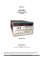
Model 3550
42.0Hz-5.00MHz
Fully Programmable
LCR Meter
MODEL 3550
Instruction Manual
PN# 3550-900-01
Publication Date: March 2010
REV. L
© Copyright 2004, TEGAM, Inc. All rights reserved.
NOTE: This user’s manual was as current as possible when this product was manufactured. However, products are
constantly being updated and improved. Because of this, some differences may occur between the descriptions in this
manual and the product received. Please refer to www.tegam.com for future updates of this manual.
Model 3550 Programmable LCR Meter Instruction Manual
a
b
Model 3550 Programmable LCR Meter Instruction Manual
Table of Contents
I
INSTRUMENT DESCRIPTION............................................................................1-1
Instrument Description ........................................................................... 1-1
Feature Overview ................................................................................... 1-1
3550 Options and Accessories .................................................................. 1-4
Performance Specifications ...................................................................... 1-5
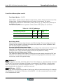
Table 1.1 – Model 3550 Measurement Range Limits ............................... 1-5
Table 1.2 – Model 3550 Measurement Frequencies ................................. 1-7
Table 1.3 – Model 3550 Measurement Amplitudes .................................. 1-7
Table 1.4 – Model 3550 Amplitude Accuracies ....................................... 1-8
Table 1.5 – Model 3550 Measurement Ranges ....................................... 1-8
Table 1.6 – Typical Analog Measurement Times ..................................... 1-9
Table 1.7a – Absolute Comparator Operation......................................... 1-11
Table 1.7b – Percentage Comparator Operation ..................................... 1-11
Table 1.8 – Numeric Displays and Annunciators ..................................... 1-11
Formulas and Measurement Accuracy ........................................................ 1-13
Table 1.9 – Series and Parallel Equivalent Circuit Measurements .............. 1-14
II
PREPARATION FOR USE ..................................................................................2-1
Unpacking and Inspection........................................................................ 2-2
Safety Information and Precautions .......................................................... 2-2
Servicing Safety Summary ...................................................................... 2-4
Line Voltage and Fuse Selection ............................................................... 2-5
III
QUICK START INSTRUCTIONS .........................................................................3-1
Power the Unit ....................................................................................... 3-2
Instrument Settings................................................................................ 3-2
Table 3.1 – Factory Default Settings .................................................... 3-2
Table 3.2 – Control Command Summary............................................... 3-3
Table 3.3 – Shift Function Summary .................................................... 3-4
Instrument Setup for Basic Measurements ................................................. 3-5
Table 3.4 – Settings Summary ............................................................ 3-5
Setting the Absolute Comparator .............................................................. 3-6
Setting the Percent Comparator ............................................................... 3-7
IV
OPERATING INSTRUCTIONS ............................................................................4-1
Basic Operation...................................................................................... 4-2
Default Parameters................................................................................. 4-2
Precautions ........................................................................................... 4-2
Measurement Tips .................................................................................. 4-2
Making Measurements that are Sensitive to Voltage and Current .............. 4-2
Measuring Earth Grounded Test Pieces ................................................. 4-2
Measurement Circuit Modes ................................................................ 4-3
Table 4.1 – Relationship Between Series and Parallel Equivalent Circuits ... 4-3
Negative Capacitance or Inductance Readings ....................................... 4-4
Zero Correction of Parasitic Impedance ................................................ 4-4
Table 4.2 – Short and Open Null Connections ........................................ 4-4
Model 3550 Programmable LCR Meter Instruction Manual
c
Table of Contents
IV
OPERATING INSTRUCTIONS CONT’D ...............................................................
Measurement Tips ..................................................................................
Test Lead Requirements ..................................................................... 4-5
Figure 4.1a – Four-Wire Kelvin Measurement ........................................ 4-5
Figure 4.1b – Proper Application of Four Wire Kelvin Measurement ........... 4-5
Measurement Signal Levels ................................................................. 4-6
Series or Parallel Circuit Modes............................................................ 4-6
Auto range Switching Threshold .......................................................... 4-6
Display Resolution ............................................................................. 4-6
AC Resistance of Coils with Cores ........................................................ 4-6
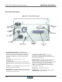
Front Panel Description ........................................................................... 4-7
Figure 4.2 – Front Panel Layout ........................................................... 4-7
Power Switch .................................................................................... 4-8
Circuit Mode Panel ............................................................................. 4-8
Trigger Panel .................................................................................... 4-8
Zero Panel ....................................................................................... 4-9
Range Selection Panel ........................................................................ 4-9
Shift Key .......................................................................................... 4-10
Frequency Set Mode ........................................................................ 4-10
Test Voltage Set Mode ..................................................................... 4-11
Test Current Set Mode ..................................................................... 4-11
Averaging Set Mode ........................................................................ 4-12
Key Lock Mode ............................................................................... 4-12
Comparator buzzer Function ............................................................. 4-13
Trigger Delay Time.......................................................................... 4-13
Comparator Functions Mode ............................................................. 4-14
Defining Spot Frequencies for Zero Adjustments ................................. 4-14
RS-232C Settings Mode ................................................................... 4-15
Correction Frequency Limit Setting Mode ............................................ 4-16
Spot Correction Mode (Open Correction) ............................................ 4-16
Spot Correction Mode (Short Correction) ............................................ 4-16
Unknown Terminals Panel ................................................................... 4-17
Table 4.3 – Unknown Terminals........................................................... 4-17
Comparator Limit Set Panel ................................................................ 4-17
The Guard Terminal ........................................................................... 4-17
Remote Interface Status LEDs ............................................................. 4-18
Panel Selector Switch......................................................................... 4-18
Panel Display LED.............................................................................. 4-18
Display A Parameter Selection Key....................................................... 4-18
Display A ......................................................................................... 4-18
Bin Display LED................................................................................. 4-18
Comparator State Annunciators ........................................................... 4-19
Sample LED (Trigger Status)............................................................... 4-19
Comparator ON/OFF Switch ................................................................ 4-19
Display B Parameter Selection Key....................................................... 4-19
Display B ......................................................................................... 4-19
d
Model 3550 Programmable LCR Meter Instruction Manual
Table of Contents
IV
OPERATING INSTRUCTIONS CONT’D ...............................................................
Front Panel Description Cont’d ............................................................
Display C Measurement Panel ............................................................. 4-20
Table 4.4 – CV/CC Indicators .............................................................. 4-21
Display C ......................................................................................... 4-21
Enter Key ......................................................................................... 4-21
Rear Panel Description ............................................................................ 4-22
Figure 4.3 – Rear Panel Layout ............................................................ 4-22
Making Accurate Measurements ............................................................... 4-23
Connections to the Device Under Test .................................................. 4-23
3-Terminal Measurement .................................................................... 4-23
4 or 5-Terminal Measurements ............................................................ 4-23
Test Fixture Selection ........................................................................ 4-24
Table 4.4 – Impedance and Frequency Limitations of Kelvin Klip Leads ..... 4-24
Table 4.5 – Impedance and Frequency Limitations of the SMD Test Fixture 4-25
Zero Corrections ............................................................................... 4-26
Table 4.6 – Zero Correction Limits ....................................................... 4-26
Figure 4.4 – Terminal Connections for Zero Correction ............................ 4-27
Equivalent Circuits ............................................................................. 4-28
Table 4.7 – Equivalent Circuit Relationships .......................................... 4-29
Operating the 3550 ................................................................................ 4-30
Preparation ...................................................................................... 4-30
How to Perform a Zero Correction ........................................................ 4-30
Measuring L, C, and R ........................................................................ 4-31
Measuring |Z| and |Y| ........................................................................ 4-33
Measuring D, Q, Rs, Rp, G, X, B, and θ ................................................. 4-34
The Comparator ..................................................................................... 4-35
Important Notes for the Absolute and Comparator Functions ................... 4-35
Absolute Value Settings...................................................................... 4-36
Percent Value Settings ....................................................................... 4-37
Bin Operation ................................................................................... 4-39
Figure 4.5 – Sequenced Bin Sorting ..................................................... 4-39
Figure 4.6 – Nested Bin Sorting ........................................................... 4-40
Outputting the Comparator’s Results .................................................... 4-41
Audible Buzzer Operation ................................................................... 4-41
Model 3550 Programmable LCR Meter Instruction Manual
e
Table of Contents
V
PROGRAMMING AND INTERFACING ................................................................5-1
Interfacing to the 3550 ........................................................................... 5-2
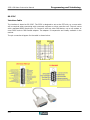
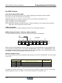
Control I/O Connector ............................................................................. 5-2
Inputs ............................................................................................. 5-2
Figure 5.1 – Input Schematic .............................................................. 5-2
Outputs ........................................................................................... 5-3
Figure 5.2 – Output Schematic ............................................................ 5-3
Timing Diagrams ............................................................................... 5-4
Figure 5.3a – Test Busy Operation ....................................................... 5-4
Figure 5.3b – Measure End Operation ................................................... 5-4
Figure 5.3c – GO/NO-GO Operation ..................................................... 5-4
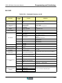
Table 5.1 – Connector Pin Designations ................................................ 5-5
Table 5.2 – Control I/O Function Summary ........................................... 5-6
Sample Diagram of External Connections to Sequencer........................... 5-7
RS-232C ............................................................................................... 5-8
Interface Cable ................................................................................. 5-8
Input Format .................................................................................... 5-9
Table 5.3a – Command Summary ........................................................ 5-12
Table 5.3b – Command Summary cont’d .............................................. 5-13
Table 5.3c – Command Summary cont’d ............................................... 5-14
Table 5.4 - Comparator Instructions..................................................... 5-15
Data Output Format for Measurement Settings ...................................... 5-16
Table 5.5a – Data Output Code Functions ............................................. 5-17
Table 5.5b – Data Output Code Functions cont’d .................................... 5-18
Monitor Output Format ....................................................................... 5-19
Table 5.6c – Monitor Output Code Functions.......................................... 5-22
Table 5.6b – Monitor Output Code Functions cont’d ................................ 5-23
RS-232C Hardware and Computer Settings ........................................... 5-24
Sample Programs for RS-232C ............................................................ 5-25
The GPIB Interface (Optional) .................................................................. 5-29
General Description of GPIB ................................................................ 5-29
Primary Specifications of GPIB ............................................................ 5-29
Table 5.7 – GPIB Functions ................................................................. 5-29
Installation of the GPIB Board ............................................................. 5-30
Figure 5.4a – Rear View ..................................................................... 5-30
Figure 5.4b – Side View ..................................................................... 5-31
Figure 5.4c – Top View ....................................................................... 5-31
Front Panel Status LEDs ..................................................................... 5-32
Local Key Switch ............................................................................... 5-32
GPIB Switches .................................................................................. 5-32
Delimiter Output Formats ................................................................... 5-32
Output Status Bits for Service Requests ................................................ 5-33
Figure 5.5 – GPIB Status Bits .............................................................. 5-33
Additional Notes for Using the GPIB Interface ........................................ 5-33
Programming Examples...................................................................... 5-34
f
Model 3550 Programmable LCR Meter Instruction Manual
Table of Contents
VI
SERVICE INFORMATION ..................................................................................6-1
Warranty .............................................................................................. 6-2
Warranty Limitations .............................................................................. 5-2
Statement of Calibration ......................................................................... 6-2
Contact Information ............................................................................... 6-2
Repair Parts .......................................................................................... 6-3
Troubleshooting .................................................................................... 6-4
Preparation for Repair or calibration Service ............................................... 6-5
Expedite Repair and calibration Form ........................................................ 6-6
Performance Verification Procedure ........................................................... 6-7
Model 3550 Calibration Adjustment Procedure ............................................ 6-12
VII
APPENDIX .......................................................................................................A.1
Setting the Constant Voltage Mode ........................................................... A.3
To Enable the Constant Voltage Mode................................................... A.3
Calculating the maximum Allowable Constant Voltage Setting .................. A.3
Setting the Constant Current Mode ........................................................... A.4
Calculating the maximum Allowable Constant Current Setting .................. A.4
Basic Measurement Accuracy Tables ......................................................... A.5
Table A.1 – Basic Accuracy Table ......................................................... A.5
Table A.2 – Basic Accuracy Table [0.01V to 0.04V]................................. A.6
Table A.3 – Basic Accuracy Table [0.05V to 0.10V]................................. A.7
Table A.4 – Basic Accuracy Table [0.11V to 0.20V]................................. A.8
Table A.5 – Basic Accuracy Table [0.21V to 0.45V]................................. A.9
Table A.6 – Basic Accuracy Table [0.46V to 1.00V]................................. A.10
Table A.7 – Basic Accuracy Table [1.01V to 5.00V]................................. A.11
LC Impedance Calculation Chart ............................................................... A.12
Error Codes ........................................................................................... A.13
Model 3550 Programmable LCR Meter Instruction Manual
g
h
Model 3550 Programmable LCR Meter Instruction Manual
Instrument Description
INSTRUMENT DESCRIPTION
PREPARATION FOR USE
QUICK START INSTRUCTIONS
OPERATING INSTRUCTIONS
PROGRAMMING & INTERFACING
SERVICE INFORMATION
APPENDIX
Model 3550 LCR Meter Instruction Manual
Instrument Description
Instrument Description
The Model, 3550, is a high-speed LCR Meter capable of measuring Inductance (L), Capacitance(C),
Resistance (R), Absolute Impedance (|Z|), Absolute Admittance (|Y|), Dissipation factor (D),
Quality (Q), Serial Equivalent Resistance (Rs), Parallel Equivalent Resistance (Rp), Conductance
(G), Reactance (X), Susceptance (B), and Phase Angle (θ). It has a wide measurement range, and
includes full adjustability of Measurement Frequency and Measurement Signal Level. It also
features Automatic adjustment for Zero Correction, Range Switching, and Series and Parallel Mode
Switching.
The basic comparator function of the 3550 is extended to allow sorting of components to up to 10
different bins. Up to 9 panels worth of measurement settings can be stored in the instrument’s
non-volatile memory for convenient recall. The instrument can perform a complete measurement
including a comparator judgment in as little as 40ms.
The 3550 has standard RS-232C and Control I/O Connector Interfaces with the availability of an
optional GPIB Interface. The Control I/Os are optically isolated thus making the instrument ideal
for noise immunity.
Feature Overview
The 3550 Programmable LCR Meter offers a complete solution for a wide variety of specialized LCR
measurement applications. Listed below are some of the features.
High Speed
The measurement time, including data display, zero correction, and comparator function is
approximately 40 milliseconds.
Extended Frequency Range
The Measurement Frequency can be adjusted between 42.0Hz - 5.00MHz.
Programmable Test Voltage and Current
The test signal level can be adjusted between 10mV to 5.00V in the constant voltage mode
and from 10μA to 99.99mA in the constant current mode.
Voltage & Current Monitor
The voltage at the test piece terminals and the current, which is flowing through the test
piece, can be displayed up to 3 significant digits.
1-2
Model 3550 LCR Meter Instruction Manual
Instrument Description
Feature Overview cont’d:
41/2 Digits Resolution
"DISPLAY A" (L, C, R, |Z|, |Y|), and "DISPLAY B" (D, Q, RS, RP, G, X, B, θ) can both display
up to 41/2 digits.
GO/NO-GO COMPARATOR
For L, C, R, |Z|, |Y|, D, Q, RS, RP, G, X, B, and θ, upper and lower limit values can be set
for 9 items (10 categories), for up to 9 panels of settings.
Series or Parallel Equivalent Circuit Mode
When in "Auto" mode, Parallel or Series Equivalent Circuit measurements are automatically
determined by the active measurement range. In manual range, the Parallel or Series
Equivalent Circuit mode are user selectable.
Front Panel Key Lock
The Key Switch on the front panel can be set to lock the instrument settings for protection
against accidental changes.
Automatic Zero Correction of Parasitic Impedance
Performing Open and Short Circuit Zeroing cancel the offset errors caused by Stray
Capacitance, Stray Conductance, Residual Inductance, and Residual Resistance.
Non-Volatile Memory
All measurement settings such as the Zero Correction Values, Comparator Limits, Panel
Settings etc. are stored in non-volatile memory and are retained in the event of power loss.
Remote Operation
The TEGAM Model 3550 provides standard RS-232C and I/O Control Connector interfaces
for remote operation. There is an optional GPIB (IEEE-488) interface available for purchase.
1-3
Model 3550 LCR Meter Instruction Manual
Instrument Description
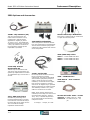
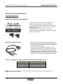
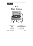
3550 Options and Accessories
2005B - Chip Tweezers (5ft)
This four-terminal tweezer set
makes solid connections to chip
components in manual sorting
applications. Capacity of jaws is
12.7mm (0.5 in.). The 2005B Chip
Component Tweezer Set includes a
1.5m (5 ft) cable for connection to
the 2150/2160. Contact tips are
replaceable. P/N 47422.
KK100- Kelvin Klip™ Rebuild Kit
Kelvin Klip™ replacements for construction
or repair of Kelvin Klip leads.
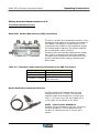
3510-Radial Lead Adapter
This sorting fixture allows for efficient
four-wire measurement of leaded parts.
The test fixture features spring action
contacts for easy insertion and removal
of test components.
GPIB (IEEE-488) Cables
1583-3 – 1-meter GPIB buss cable
1583-6 – 2-meter GPIB buss cable
1583-9 – 3-meter GPIB buss cable
47422 Chip Tweezer
Replacement Kit
Tweezer tips are intended to last
100,000 to 500,000 operations. An
optional tip replacement kit includes
12 replacement tips, 2 screws and 1
wrench.
3511 - SMD Test Fixture
Available for performing three
terminal measurements on surface
mount devices. Connects directly to
the front panel of the 3550. Use the
3511 for medium and high
impedance measurements.
1-4
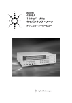
47454 – Kelvin Klips
Kelvin Klips allow solid four-terminal,
Kelvin connections to leaded
components. The jaws are assembled
with hardened gold-plated, beryllium
copper, which ensures low contact
resistance, low thermal emf to copper,
high corrosion resistance, and long
service life. An alligator clip is provided
allowing connection of a passive guard.
The assembly includes a 5 ft (1.5m)
cable for connection to the 3525.
NOTE: Under certain measurement
conditions, Kelvin Klips can cause a loss
of measurement accuracy. Fixtures
3510, 3511, or 2005B chip tweezers
are recommended for the following
component values:
C<100pF; L < 100μH; R > 1MΩ
3505 – GPIB Interface
3550-900-01 – User’s ManualHard Copy
RS-232 Null Cable 9PIN – 25 PIN
740570-6 - 6’ Cable null 9 pin – 25pin
740570-10 - 10’ Cable null 9 pin – 25
pin
Model 3550 LCR Meter Instruction Manual
Instrument Description
Performance Specifications
The advertised specifications of the model 3550 are valid under the following conditions:
1. The instrument must be verified and/or adjusted using the methods and intervals as
described in the calibration section of this user’s manual.
2. The instrument must be in an environment, which does not exceed the limitations as
defined under “Environmental” in the Miscellaneous Specifications section.
3. The unit is allowed to warm up for a period of at least 30 minutes before measurements
are taken. A warm-up period of 60 minutes is recommended after exposure to or storage in
a high humidity, (non-condensing), environment.
4. Only TEGAM-manufactured Kelvin Klips™, Tweezers and other test fixtures are used with
this device during measurements.
Measurement Parameters:
Inductance (L), Capacitance(C), Resistance(R), Impedance (|Z|), Admittance (|Y|),
Dissipation Factor (D), Quality (Q), Equivalent Series Resistance (RS), Equivalent Parallel
Resistance (RP), Conductance (G), Reactance (X), Susceptance (B), and Phase Angle (θ).
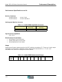
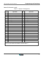
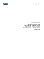
Measurement Ranges
Table 1.1 – Model 3550 Measurement Range Limits
Parameter
L
C
R
|Z|
|Y|
D
Q
RS
RP
G
X
B
θ
Low Limit
320.0nH (At: 10Ω 5MHz)
0.160pF (At: 100kΩ 5MHz)
0.01mΩ
0.01mΩ
5.000nS(199.99MΩ)
0.0001
0.1
0.01mΩ
0.01mΩ
5.000nS(199.99MΩ)
0.01mΩ
5.000nS(199.99MΩ)
-180.00°
High Limit
0.7500MH(At: 199.99MΩ 42Hz) (θ=90°)
0.037F(At: 100mΩ 42Hz) (θ=-90°)
199.99MΩ
199.99MΩ
100.00S(100mΩ)
9.999
1999.9
199.99MΩ
199.99MΩ
100.00S(100mΩ)
199.99MΩ
100.00S(100mΩ)
180.00°
NOTE: The Measurement Range is dependent on the Measurement Frequency. The figures in
parentheses are DUT impedance values.
1-5
Model 3550 LCR Meter Instruction Manual
Instrument Description
Performance Specifications cont’d:
Basic Accuracy
0.1%
Display Specifications:
Numeric Display (DISPLAY A)
L, C, R, |Z|, |Y| (41/2 digits)
Numeric Display (DISPLAY B)
D, Q, RS, RP, G, X, B, θ (41/2 digits)
Numeric Display (DISPLAY C)
Frequency, Voltage, Current, Terminal Voltage, Terminal Current, PANEL (3 digits)
Unit Prefix Display (DISPLAY A)
p, n, μ, m, k, M
Unit Prefix Display (DISPLAY B)
n, μ, m, k, M
Unit Display (DISPLAY A)
F, H, Ω, S
Unit Display (DISPLAY B)
Ω, S, deg
Unit Display (DISPLAY C)
Hz, kHz, MHz, V, mA
Switch Indicator Lamps
1-6
RANGE – AUTO; UP; DOWN
CIRCUIT MODE – AUTO; SER; PRL
SHIFT
DISPLAY C – V; I; CV/CC
TRIGGER - INT; MAN/EXT
SAMPLE
Instrument Description
Model 3550 LCR Meter Instruction Manual
Performance Specifications cont’d:
Measurement Frequency
Table 1.2 – Model 3550 Measurement Frequencies
Frequency Range
42.0Hz ~99.9Hz
100Hz~999Hz
1.00kHz~9.99kHz
10.0kHz~99.9kHz
100kHz~999kHz
1.00MHz~5.00MHz
Resolution
0.1Hz Steps
1Hz Steps
10Hz Steps
100Hz Steps
1kHz Steps
10kHz Steps
Measurement Frequency Accuracy
±0.01%
Measurement Signal Level
Table 1.3 – Model 3550 Measurement Amplitudes
Frequency Range
42.0Hz~1.00MHz
1.01MHz~5.00MHz
Test Voltage
Range
0.01~5.00Vrms
0.05~1.00Vrms
Test Current Range
0.01~99.99mArms
0.05~20.00mArms
Open Terminal Voltage Mode
Increment/Resolution
Max. Shorting Current
0.01V Steps
99.99mA (Dependent on Measurement Frequency)
Fixed Voltage Mode
Increment/Resolution
Max. Shorting Current
0.01V Steps
99.99mA(Dependent on Measurement Frequency)
Fixed Current Mode
Increment/Resolution
Max. Shorting Current
0.01mA Steps
99.99mA(Dependent on Measurement Frequency)
1-7
Instrument Description
Model 3550 LCR Meter Instruction Manual
Performance Specifications cont’d:
Monitor Functions
Voltage Monitor
Current Monitor
0.00V~5.00V
0.00mA~99.99mA
Settings and Monitor Accuracy
Table 1.4 – Model 3550 Amplitude Accuracies
Frequency Range
42.0Hz~4.00MHz
4.01MHz~5.00MHz
Test Voltage
Accuracy
±(10%+10mV)
±(20%+10mV)
Test Current
Accuracy
±(10%+10μA)
±(20%+10μA)
Signal Source Impedance
50Ω ±10%
Measurement Circuit Modes
Auto/Manual Circuit Selection
Parallel Equivalent Circuit Mode
Series Equivalent Circuit Mode
Range
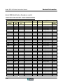
Measurement Range is determined by the DUT’s absolute impedance |Z|. There are 9 total ranges
selectable in either AUTO or MANUAL modes. Measurement parameters (L, C, R, etc.) are
calculated from actual test voltage and current values.
Table 1.5 – Model 3550 Measurement Ranges
Range
Upper
Limit
|Z|
1-8
1
100mΩ
2
1Ω
3
10Ω
4
100Ω
5
1kΩ
6
10kΩ
7
100kΩ
8
1MΩ
9
10MΩ
AUTO
100mΩ~10MΩ
Model 3550 LCR Meter Instruction Manual
Instrument Description
Performance Specifications cont’d:
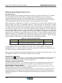
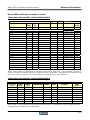
Measurement Time
Open Terminal Voltage Mode
When the Measurement Frequency is 10kHz, no averaging, the range is held constant, RS-232C is
OFF and the Comparator is ON, the shortest measurement time is 18ms.
Typical Analog Measurement Times
Conditions: Averaging= 1, range held, RS-232C is OFF, and Comparator ON:
Table 1.6 – Typical Analog Measurement Times
Test Frequency
Typical Analog Measurement Time
42Hz
120Hz
1kHz
10kHz
100kHz
1MHz
5MHz
624ms Max.
221ms Max.
31ms Max.
18ms Max.
30ms Max.
25ms Max.
21ms Max.
About the Typical Analog Measurement Time
The Typical Analog Measurement Time is dependent upon the Measurement Frequency. For ranges
42.0Hz~750Hz, and 10.1kHz~19.0kHz, Typical Analog Measurement Time will exceed 40 ms.
For other frequencies, 40ms will not be exceeded.
(Conditions: Averaging = 1, range held, RS-232C is OFF, and Comparator ON)
With the RS-232C turned on and set to a baud rate of 9600 BPS, the additional time needed for
RS-232C communication is 100ms at any frequency setting.
Fixed Voltage/Fixed Current Mode
The measurement time can be up to 4X the time of the Open Terminal Voltage Mode.
Average Mode
The user can define from 1~100 averages.
1-9
Model 3550 LCR Meter Instruction Manual
Instrument Description
Performance Specifications cont’d:
Measurement Terminals
2 – BNC Source Terminals
2 – BNC Detect Terminals
1 – Guard Banana/Binding Post
Parasitic Impedance Correction
Open Correction
Short Correction
1kΩ or higher Impedance
Less than 1kΩ Impedance
Programmable Delay Time
Measurements will be started after a trigger is detected from the front panel, Control I/O
Connector or RS232C interface. The delay time setting is user-definable and ranges from
0~10 seconds in 1ms increments.
GO/NO-GO Limits Comparator/Binning
Absolute Value
Absolute Settings must fall within the Measurement Ranges of DISPLAY A and DISPLAY B.
Comparator Settings must be applied to existing preset panels.
Up to 9 programmable bins (1-9) may be defined. Bin 0 is reserved for measured values
that fall outside of the limits.
User may program the High or Low limits of DISPLAY A and DISPLAY B to be ignored.
Percent Value
1-10
Percent Settings must fall within the Measurement Ranges of DISPLAY A and DISPLAY B.
Limit Values of 00000~999.99 % for both DISPLAY A and DISPLAY B
Comparator Settings must be applied to existing panels.
Up to 9 programmable bins (1-9) may be defined. Bin 0 is reserved for measured values
that fall outside of the limits.
User may program the High or Low limits of DISPLAY A and DISPLAY B to be ignored.
Instrument Description
Model 3550 LCR Meter Instruction Manual
Performance Specifications cont’d:
Comparator/Binning: Absolute Limits Operation
Operation
Bins 1~9
LO
HI
TOTAL GO
Table 1.7a – Absolute Comparator Operation
Function
"LOW LIMIT"≤ Measurement Value ≤"HIGH LIMIT"
Measurement Value < "LOW LIMIT"
"HIGH LIMIT" < Measurement Value
When both DISPLAY A and DISPLAY B are not LO or HI
Comparator/Binning: Percent Limits Operation
*The location of the decimal point affects the % comparator/binning values.
Operation
Bins 1~9
LO
HI
TOTAL GO
Table 1.7b – Percentage Comparator Operation
Function
"LOW LIMIT"≤ Measurement Value ≤"HIGH LIMIT"
Measurement Value < "LOW LIMIT"
"HIGH LIMIT" < Measurement Value
When both DISPLAY A and DISPLAY B are not LO or HI
Displays
Table 1.8 – Numeric Displays and Annunciators
Display
Display Description & Range
Numeric DISPLAY A
Numeric DISPLAY B
Unit Prefix Annunciators for DISPLAY A
Unit Prefix Annunciators for DISPLAY B
Unit Annunciators for DISPLAY A
Unit Annunciators for DISPLAY B
Comparator Limit
Comparator Enabled
Comparator State
Comparator Total GO
-19999 ~ 19999 (4-1/2 digits)
-19999 ~19999 (4-1/2 digits)
p, n, μ, m, k, M
n, μ, m, k, M
F, H, Ω, S
Ω, S, deg
LOW & HIGH Pushbuttons
ON Pushbutton
LO-HI (For DISPLAY A & B)
TOTAL GO LED
BIN
PANEL
GPIB Status
0-9 Seven Segment LED Display
0-9 Seven Segment LED Display
SRQ, LTN, TLK, RMT
1-11
Model 3550 LCR Meter Instruction Manual
Instrument Description
Performance Specifications cont’d:
Digital Interfaces
RS-232C Standard interface
GPIB Optional Interface
Control I/O Standard Interface Connector
External Control Signals
CONTROL PANEL/EXT, EXT TRIGGER, PANEL No. (Isolated)
External Output Signals
MEASURE END, ERROR, DISPLAY A HI, DISPLAY A LO, DISPLAY A GO, DISPLAY B LO, DISPLAY B HI,
DISPLAY B GO, TOTAL GO, TOTAL NO-GO, BIN (Optically Isolated)
Audible Buzzer
Can be set to turn ON with GO or NO-GO comparator state; or it can be disabled.
Panel Presets
9 panel presets including comparator settings can be programmed into non-volatile
memory.
Front Panel Key Lock
Protects accidental changing of front panel settings all panel keys except the Manual
Trigger are disabled.
Environmental
Operating Temperature = 5°C~40°C (41°F~104°F) <80%RH Non-Condensing
o Accuracy specifications are based on temperature conditions within 23°C±5°C
(73.4°F±9°F).
o For temperatures exceeding 23°C±5°C and still within the operating temperature,
the margin of error will be 2 times larger.
Power Source
Operating Voltage=100/120/220/240V AC ±10%(MAX250V)
Power Frequency=50/60Hz
Maximum Power Usage=40VA
Dimensions
Width: 9.84” (250mm)
Height: 5.83” (148mm)
Depth: 15.74” (400mm)
Weight
Approximately 15.4lb (7kg)
1-12
Model 3550 LCR Meter Instruction Manual
Instrument Description
Formulas and Measurement Accuracy
Parameters and Formulas
I
Z
V
IMAGINARY NUMBERS
Generally speaking, the characteristics of circuit components can be evaluated in terms of
impedance (Z).
The 3550 LCR Meter measures the voltage and current components of the circuit in relation to the
alternating signal of the measurement frequency, and uses these values to calculate impedance
(Z) and phase angle (θ).
Displaying impedance (Z) in a complex notation as below allows us to determine the following
values.
Z
jX
θ
Z =V / I
R
REAL NUMBERS
Z=R+jX
θ = TAN-1 X/R
R2 +X2
|Z| =
Z: Impedance (Ω)
θ: Phase Angle (deg)
R: Resistance (Ω)
X: Reactance (Ω)
|Z|: Absolute Value of Impedance (Ω)
Depending on the properties of the DUT, Admittance (Y), which is the inverse of Impedance (Z),
may be used to calculate parameter values instead. Admittance (Y), like Impedance (Z) can be
represented in complex notation in order to calculate the following values.
IMAGINARY NUMBERS
Y=G+jB
Φ= TAN-1 (B*G)
|Y|=
G2 +B2
Y: Admittance (S)
G: Conductance (S)
B: Susceptance (S)
|Y|: Absolute value of Admittance (S)
REAL NUMBERS
G
φ
jB
Y
1-13
Instrument Description
Model 3550 LCR Meter Instruction Manual
Formulas and Measurement Accuracy cont’d:
The 3550 calculates the various measurement values using the inter-terminal voltage (V) applied
to the DUT (device under test) terminals, the current (I) that occurs in relation to the voltage, the
Phase Angle (θ) of (V) and (I), and the Angular Velocity (ω) of the measurement frequency.
These factors are used in the formulas below to determine values for the measurements made by
the TEGAM 3550.
Note: The Phase Angle is based on Impedance (Z). In order to base the Phase Angle on
Admittance (Y), add a "-" sign to the Impedance value to negate it.
Thus, φ for Admittance will be φ=-θ.
Item
Table 1.9 – Series and Parallel Equivalent Circuit Measurements
Series Equivalent Circuits
Parallel Equivalent Circuits
Z
|Z| = V/I(
Y
|Y| = 1/|Z|(
R
RS = ESR = | |Z|cosθ |
X
X = |Z| sinθ
G
B
L
C
D
Q
R2 +X2
)
G2 +B2 )
RP = EPR = | 1/(|Y|cosθ) | = 1/G
|Y|cosθ ***
B = |Y|sinθ ***
LS = X/ω
LP = 1/(ω*B)
CS = 1/(ω*X)
CP = B/ω
D = 1/tanθ = 1/Q
Q = tanθ = 1/D
*** φ is the Phase Angle of Admittance: φ = -θ
LS, CS, RS represent the L, C, R measurements for series equivalent circuits.
LP, CP, RP represent the L, C, R measurements for parallel equivalent circuits.
1-14
Model 3550 LCR Meter Instruction Manual
Instrument Description
Measurement Accuracy
The impedance of the DUT is either the actual measured value or a value, which is derived from
the formulas below:
If θ=90° → |Z| = ωL
If θ= -90° → |Z| = 1/ωC
If θ=0° → |Z| = R
Voltage Level Accuracy Limit
See the Measurement Accuracy Tables located in the Appendix. The tables contain formulas for
calculating the Voltage Level Accuracies.
1-15
Model 3550 LCR Meter Instruction Manual
1-16
Instrument Description
Preparation for Use
INSTRUMENT DESCRIPTION
PREPARATION FOR USE
QUICK START INSTRUCTIONS
OPERATING INSTRUCTIONS
PROGRAMMING & INTERFACING
SERVICE INFORMATION
APPENDIX
Model 3550 LCR Meter Instruction Manual
2-1
Model 3550 LCR Meter Instruction Manual
Preparation for Use
Unpacking & Inspection:
Each 3550 is put through a series of electrical and mechanical inspections before shipment to the
customer. Upon receipt of your instrument unpack all of the items from the shipping carton and
inspect for any damage that may have occurred during transit. Report any damaged items to the
shipping agent. Retain and use the original packing material for reshipment if necessary.
Upon Receipt, inspect the carton for the following items:
Model 3550 General Purpose, Programmable LCR Meter
Model 3550 User’s Manual CD
Power Cord
!
Safety Information & Precautions:
The following safety information applies to both operation and service personnel. Safety
precautions and warnings may be found throughout this instruction manual and the equipment.
These warnings may be in the form of a symbol or a written statement. Below is a summary of
these precautions.
Terms in This Manual:
CAUTION statements identify conditions or practices that could result in damage to the equipment
or other property.
WARNING statements apply conditions or practices that could result in personal injury or loss of
life.
Terms as Marked on Equipment:
CAUTION indicates a personal injury hazard not immediately accessible as one reads the marking,
or a hazard to property including the equipment itself.
DANGER indicates a personal injury hazard immediately accessible as one reads the marking.
2-2
Model 3550 LCR Meter Instruction Manual
!
Preparation for Use
Safety Information & Precautions Cont’d:
Symbols:
As Marked in This Manual:
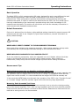
!
This symbol denotes where precautionary information may be found.
As Marked on Equipment:
!
Caution – Risk of Danger
Danger – Risk of Electric Shock
Earth Ground TerminalOn
Off
Chassis Terminal
Alternating Current
Earth Ground Terminal / Guard
Grounding the Equipment
This product is grounded through the grounding conductor of the power cord.
WARNING: To avoid electrical shock or other potential safety hazards, plug the power cord into a
properly wired receptacle before using this instrument. The proper grounding of this instrument is
essential for safety and optimizing instrument operation.
Danger Arising from Loss of Ground
WARNING: If the connection to ground is lost or compromised, a floating potential could develop
in the instrument. Under these conditions all accessible parts, including insulating parts such as
keypads and buttons could develop a hazardous voltage and put the user at risk.
2-3
Model 3550 LCR Meter Instruction Manual
Preparation for Use
!
Use the Proper Fuse
To avoid fire hazard, use only the correct fuse type as specified for the AC power supply in the
“Preparation for Use”” or “Service” sections of this manual. Please note that the fuse rating for 100
& 120-volt operation is different than the rating for 200 & 240-volt operation. Information about
the proper fuse type is also printed on the rear panel of the instrument.
Refer fuse replacement to qualified service personnel.
Do Not Use in Explosive Environments
WARNING: The 3550 is not designed for operation in explosive environments.
Do not Operate Without Covers
WARNING: This device should be operated with all panels and covers in place. Operation with
missing panels or covers could result in personal injury.
FOR QUALIFIED SERVICE PERSONNEL ONLY
!
Servicing Safety Summary:
Do Not Service Alone
Do not perform service or adjustment on this product unless another person capable of rendering
first aid is present.
Use Care When Servicing with Power On or Off
Dangerous voltages may exist at several points in this product. To avoid personal injury or
damage to this equipment, avoid touching exposed connections or components while the power is
on. Assure that the power is off by unplugging the instrument when removing panels, soldering, or
replacing components.
WARNING: The instrument power source is electronically controlled meaning that there is power
present throughout the instrument even when the instrument is in the OFF state.
Always unplug the instrument and wait 5 minutes before accessing internal components.
Power Source
This product is intended to connect to a power source that will not apply more than 250V RMS
between the supply conductors or between either supply conductor and ground. A protective
ground connection by way of the grounding conductor in the power cord is essential for safe
operation.
2-4
Preparation for Use
Model 3550 LCR Meter Instruction Manual
!
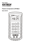
Line Voltage & Fuse Selection:
CAUTION: DO NOT APPLY POWER TO THE INSTRUMENT BEFORE READING THIS SECTION:
Unless other wise specified, the Model 3550 is delivered from TEGAM with its power supply set for
120V, 60 Hz operation. However, the 3550 design allows it to operate under 100, 120V, 220 or
240V @ 50/60 operation. It is strongly recommended that the line voltage and fuse size be
verified before powering the unit.
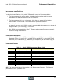
First, determine the supply voltage that the instrument will be operating under and verify that the
supply voltage does not fall outside of the allowable ranges in the table below:
LINE VOLTAGE RANGE
100/120V
90~132VAC
220/240V
198~250VAC
FUSE SIZE
1A
0.5A
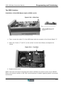
Units Made Prior to October 2008
Make sure that the proper fuse size is installed.
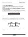
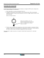
Next, verify that the jumper block in the rear panel of the instrument is securely plugged into the
correct position. There are four positions that the block may be set to. Set the jumper block to
point to one of the four voltage settings. You can remove the jumper block by pulling it from the
jumper socket.
240V
120V
220V
100V
Unit set for 120VAC Operation 50/60Hz
The instrument is ready for power up. Proceed to “Quick Start Instructions” for continued
operation.
2-5
Model 3550 LCR Meter Instruction Manual
Preparation for Use
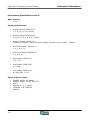
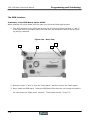
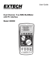
Units Made After October 2008
The following procedure describes the steps necessary to change the 3550 power settings from
factory default settings to a new setting.
1. Verify that there is no power connected to the unit.
2. Change the line selector switch located on the rear panel of the 3550 to the desired
operating voltage by using a small screwdriver to turn the voltage selection switch to the
desired position.
Refer to the figure below:
With your screwdriver, turn the
desired voltage number to the black
arrow. For example, the setting
here is for 240V.
3. The fuse size may need to be changed as a result of the increased or decreased voltage
operation. Please refer to the table above for detailed fuse information. The rear panel of
the 3550 will also contain information regarding fuse sizes and types.
The instrument is ready for power up. Proceed to “Quick Start Instructions” for continued
operation.
2-6
Quick Start Instructions
SPECIFICATIONS
PREPARATION FOR USE
QUICK START INSTRUCTIONS
OPERATING INSTRUCTIONS
PROGRAMMING & INTERFACING
SERVICE INFORMATION
APPENDIX
Model 3550 LCR Meter Instruction Manual
3-1
Quick Start Instructions
Model 3550 LCR Meter Instruction Manual
The Model 3550 is a versatile product, which can be used in many different configurations.
Because of its ability to measure a large number of impedance parameters under a dynamic range
of test frequencies, amplitudes, and configurations, its is highly recommended that the entire
“Operating Instructions” Section of this manual be reviewed to insure proper use of this
equipment.
This Quick Start section is designed to give the user a general instruction set for the speedy setup
and measurement of impedance values where arbitrary measured values are needed and accuracy
is not critical. Whenever additional information is applicable, a reference will be made to other
parts of this manual so that the user, at their discretion, can decide whether or not to pursue
additional information.
Power the Unit
The power supply of the Model 3550 is designed for 50-60 Hz operations and a voltage range of
90-250 VAC. It is assumed that the “Preparation for Use” section of this manual has been read an
understood and the line voltage and fuse settings have been verified to be correct.
Power the unit by depressing the pushbutton located on the lower right corner of the front panel.
Allow at least 30 minutes for the unit to warm up and verify that the unit will be operated in its
specified operating environment described on page 1-12.
Instrument Settings
Factory Default Settings
Before performing an actual impedance measurement, there are a number of test parameters,
which must be defined. The factory default settings can be used for most general-purpose
measurements.
The 3550 is shipped from the factory with default settings as follows:
Table 3.1 – Factory Default Settings
1
2
3
4
5
6
7
8
Parameter
DISPLAY A
DISPLAY B
DISPLAY C
Comparator
Comparator
Zero Correction
Test Frequency
Measurement Mode
Setting
Capacitance
Dissipation Factor
Frequency
Data Cleared
OFF
Data Cleared
1kHz
Open Terminal
Voltage
* not storable in a
9
10
11
12
13
14
15
Parameter
Communications
Trigger
PANEL
Circuit Mode
Range
LOCK
Test Voltage
Setting
*RS232
INT
0
AUTO
AUTO
OFF
1.00 V
setup location.
At any time during use, you may recall these default settings by pressing the [MAN/EXT] key while
powering the unit.
NOTE: When the unit is reset to factory defaults, user-defined comparator settings and zero
correction factors will be lost.
3-2
Quick Start Instructions
Model 3550 LCR Meter Instruction Manual
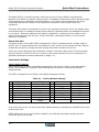
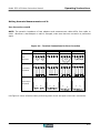
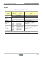
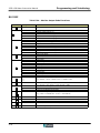
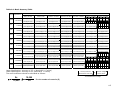
Table 3.2a – Control Command Summary
Display
Commands
Basic Commands
80
Applied Commands
1
Change measure item of DISPLAY A
A
2
Change measure item of DISPLAY B
B
3
Show measure frequency on DISPLAY C
FREQ
4
Show terminal voltage on DISPLAY C
V
5
Show measure. current on DISPLAY C
I
6
Change panel number
0-9
7
Change measurement frequency
FREQ → DISPLAY C's UP and DOWN
8
Change measurement voltage
V → DISPLAY C's UP and DOWN
9
Carry out open correction
OPEN
10
Carry out short correction
SHORT
11
Change to auto range
RANGE's AUTO
12
Change to auto circuit mode
CIRCUIT MODE's AUTO
13
Change to fixed voltage mode
14
Change the fixed voltage setting
15
Change to fixed current mode
16
Change the fixed current setting
When I and CV/CC LED are flashing
DISPLAY C's UP and DOWN
17
Raise the range
RANGE's UP
18
Lower the range
RANGE's DOWN
19
Parallel equivalent circuits mode
PRL
20
Serial equivalent circuits mode
SER
21
Measure with continuous trigger
INT
22
Measure with manual (single shot) trigger
MAN/EXT → MAN/EXT
23
Set comparator lower limit
LOW
24
Set comparator upper limit
HIGH
25
Turn comparator on
ON
26
Move cursor forward in setting mode
27
Move cursor backward in setting mode
V → CV/CC
When V and CV/CC LED are flashing,
DISPLAY C's UP and DOWN
I → CV/CC
→ MAN/EXT →
Shift
Commands
28
Set measurement frequency
SHIFT → 0 → Frequency Value → ENTER
29
Set voltage for measurement or fixed voltage
mode
SHIFT → 1 → Voltage Value (V) → ENTER
30
Set current for fixed current mode
SHIFT → 2 → Current Value (mA) → ENTER
31
Set number of measurements
SHIFT → 3 → Number Setting → ENTER
3-3
Quick Start Instructions
Model 3550 LCR Meter Instruction Manual
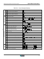
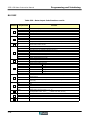
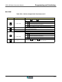
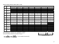
Table 3.2b – Control Command Summary cont’d
Shift Commands
32
Release Key Lock
SHIFT → 4 → 0 → ENTER
33
Lock Key
SHIFT → 4 → 1 → ENTER
34
No buzzer for decision
SHIFT → 5 → 0 → ENTER
35
Buzzer for GO decision ON
SHIFT → 5 → 1 → ENTER
36
Buzzer for NO GO decision ON
SHIFT → 5 → 2 → ENTER
37
Set start delay time
SHIFT → 6 → delay time (ms) → ENTER
38
To use absolute value comparator
SHIFT → 7 → 0 → ENTER
39
To use percent comparator
SHIFT → 7 → 1 → ENTER
st
40
Set 1 spot correction frequency
SHIFT → 8 → 1 → frequency value → ENTER
41
Set 2nd spot correction frequency
SHIFT → 8 → 2 → frequency value → ENTER
42
Set 3rd spot correction frequency
SHIFT → 8 → 3 → frequency value → ENTER
43
Set low frequency of correction
SHIFT → - → 1 → frequency value → ENTER
44
Set high frequency of correction
SHIFT → - → 2 → frequency value → ENTER
45
Do spot or open correction
SHIFT → OPEN
46
Do spot or open correction
SHIFT → SHORT
47
Change RS-232C baud rate
SHIFT → 9 → 1 → Setting → ENTER
48
Change RS-232C data length setting
SHIFT → 9 → 2 → Setting → ENTER
49
Change RS-232C parity setting
SHIFT → 9 → 3 → Setting → ENTER
50
Change RS-232C stop bit setting
SHIFT → 9 → 4 → Setting → ENTER
Table 3.3 - Shift Function Summary
SHIFT
3-4
0
Set measurement frequency
SHIFT
1
Set voltage for measure voltage/fixed
voltage mode
SHIFT
2
Set current for fixed current mode
SHIFT
3
Set number of measurements
SHIFT
4
Set key lock
SHIFT
5
Set buzzer
SHIFT
6
Set start delay time
SHIFT
7
Set comparator mode
SHIFT
8
Set spot correction frequency
SHIFT
9
Set RS-232C communication parameters
SHIFT
-
Set correction frequency limits
SHIFT
OPEN
Do spot open correction
SHIFT
SHORT
Do spot short correction
Model 3550 LCR Meter Instruction Manual
Quick Start Instructions
Instrument Setup for Basic Measurements
To perform basic measurements with the Model 3550, perform the steps below: Refer to
“Operating Instructions” for more details about specific commands or functions of the 3550.
NOTE: The numerals in parentheses reference the Control Command Tables on the previous pages. The
letters in parentheses reference the Settings Summary below:
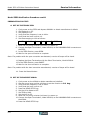
Perform an open and closed circuit zero correction {Normal correction (9,10), Frequency
limit correction (F), or Spot correction (E)} on the test leads or fixture.
Set DISPLAY A measurement parameters (1)
Set DISPLAY B measurement parameters (2)
Set measurement frequency (7 or 28)
Set measurement mode {Voltage (8 or 29), Constant Voltage (A), or Constant Current (B)}
Set the comparator limits and operation if necessary {Absolute Comparator (C) or Percent
Comparator (D)}
Set the trigger mode {Continuous (21) or One-Shot (22) trigger}
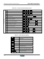
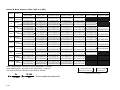
Table 3.4 - Settings Summary
A
B
C
To use fixed voltage
mode
To use fixed current
mode
To use absolute
value comparator
D
To use percent
comparator
E
To use spot
correction
F
To use frequency
limit correction
Set voltage for fixed voltage mode (14 or 29)
Change to fixed voltage mode (13)
Set current for fixed current mode (16 or 30)
Change to fixed current mode (15)
Select absolute value comparator (38)
Set comparator lower limit value (23)
Set comparator upper limit value (24)
Turn comparator ON (25)
For comparator setting details, see absolute value
comparator setting instructions.
Select percent comparator (39)
Set comparator lower limit value (23)
Set comparator upper limit value (24)
Turn comparator ON (25)
For comparator setting details, see percent
comparator setting instructions.
Set spot correction frequency (40~42)
Carry out spot-open correction (45)
Carry out spot-short correction (46)
Set upper frequency limit for correction (44)
Set lower frequency limit for correction (43)
Carry out open correction (9)
Carry out short correction (10)
3-5
Model 3550 LCR Meter Instruction Manual
Quick Start Instructions
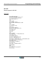
Setting the Absolute Comparator
To set the Absolute Value Comparator, following the procedure below:
1.
Select either the upper or lower comparator limit.
To input an upper limit, press [HIGH]
To input a lower limit, press [LOW]
2.
Input the BIN No.
After the [HIGH] or [LOW] key is pressed, the BIN LED will begin to flash. Use keys [1]~[9]
to designate the number.
3.
Input a limit value for DISPLAY A
After selecting the bin number, use the cursor to highlight DISPLAY A.
Enter the 5-digit upper or lower value using the keys [1]~[9]. When this is complete, the
decimal point will flash.
Press [DP] to move the decimal point to the position of the setting value.
Use the cursor [►] to highlight the unit. Here, each time [UNIT] is pressed, the unit will
change. Designate the unit for the Nominal value.
4.
Input a limit value for DISPLAY B
When the setting for DISPLAY A is complete, use the cursor [►] to highlight DISPLAY B.
Enter the 5 digits, decimal point and unit as done for DISPLAY A.
If the setting is a negative value, use the cursors keys, [►] or [◄] to highlight the 1st digit
of DISPLAY B.
Press [-] to negate the value.
5.
Finalize the Comparator Settings
If defining an upper limit, press [HIGH] to complete the setting.
If defining a lower limit, press [LOW] to complete the setting.
To input settings for other bins, repeat the steps above.
6.
Invalidating the DISPLAY A or DISPLAY B Comparator settings.
To invalidate the settings, take the cursor, [►] or [◄], to any digit location in DISPLAY A or
DISPLAY B. Then press [IGNORE] to invalidate the settings of DISPLAY A or DISPLAY B.
NOTES:
The comparator can only be set using panels [1]~[9]. [0] is not used.
The above procedure applies only to the Absolute Value Comparator. The procedure for
setting the Percent Comparator is different. Before attempting to set the Absolute
Comparator limits, verify that the 3550 is in the Absolute Comparator Mode.
After setting the limit values for the comparator, the measurement parameters for
DISPLAY A and DISPLAY B cannot be changed. The measurement parameters must be
defined before the comparator is set.
For DISPLAY B, there are no units for D,Q, or θ.
3-6
Model 3550 LCR Meter Instruction Manual
Quick Start Instructions
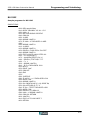
Setting the Percent Comparator
To set the Percent Comparator, follow the procedure below.
The upper and lower limit for the nominal value are the same. For the threshold values, different
values for the upper and lower limit must be set. In order to proceed, the 3550 must be in the
percent comparator mode.
1.
Select the Upper or Lower Limit to Enter the % Comparator Mode
To input the Nominal value, press the [HIGH] key. (The [LOW] key may also be pressed to
enter the % Comparator Set Mode)
2.
Select the Nominal Value Input Mode
To input the Nominal Value, press [0] when the first digit of DISPLAY C is flashing.
3.
Input the BIN No.
After selecting the Nominal Value Input Mode, use the cursor [►] to highlight the bin
number, and then press [1]~[9] to select the desired bin.
4.
Set the Nominal Value for DISPLAY A
After inputting the bin number, use the cursor, [►] to highlight DISPLAY A. Enter a 5 digit
Nominal Value for DISPLAY A using keys [0]~[9]. (NOTE: The 1st digit, is restricted to only a
“1” or “0” setting.)
When this is complete, the decimal point will flash. Press [D.P] to move the decimal point to
the desired position. Then, use the cursor [►] to highlight the unit. Press the [UNIT] key
until the required unit annunciator is lit. This designates the measurement unit for the
Nominal value.
5.
Input the Nominal Value for DISPLAY B
When the setting for DISPLAY A is complete, use the cursor [►] to highlight DISPLAY B.
Enter the 5 digits, decimal point and unit just as in DISPLAY A.
If the setting is to be a negative value, use cursors [►] or [◄] to highlight the 1st digit of
DISPLAY B then press [-] to negate the value.
6.
Completing the Nominal Value Setting
Press the [HIGH] key to finalize the Nominal Value Setting for the % Comparator.
(If the [LOW] key was pressed to enter into the % Comparator Mode then press it instead of
the [HIGH] key to exit the mode and finalize the settings.)
7.
Set an Upper or Lower Limit for the % Threshold Values
To input an upper limit threshold value, press the [HIGH] key. Press the [LOW] key to set
the lower limit threshold value. Then, highlight the first digit of DISPLAY C and press [1].
3-7
Model 3550 LCR Meter Instruction Manual
Quick Start Instructions
Setting the Percent Comparator
8.
Input the BIN No.
After selecting the threshold value input mode, use the cursor key, [►] to highlight the bin
LED, and then press [1]~[9] to select the desired bin.
9.
Input the Threshold Value for DISPLAY A
After entering the bin number, use the cursor key [►] to highlight DISPLAY A.
Enter the 5-digit threshold value for DISPLAY A using keys [0]~[9]. (The setting range is
from 000.00%~199.99%)
10.
Input the Threshold Value for DISPLAY B
Enter the 5-digit threshold value for DISPLAY B using keys [0]~[9]. (The setting range is
000.00%~199.99%)
11.
Finalizing the Setting
To finalize an upper limit, press [HIGH] or press [LOW] to finalize a low limit setting.
NOTE: Whether a high or low limit %comparator setting is defined is determined in step 7.
To input settings for other bins, return to Step 1 and repeat the process.
12.
Invalidating the DISPLAY A or DISPLAY B Percent Comparator settings
To invalidate the settings, for threshold values, simply enter the Threshold Percent
Comparator Set Mode and move the cursor to any segment in DISPLAY A or DISPLAY B. Then
press [IGNORE] to invalidate the % comparator settings for that DISPLAY.
NOTES:
The comparator can only be set using panels 1~9. 0 cannot be used.
This procedure is only for the percent comparator setting. Note that the procedure for the
absolute value comparator is different.
Make sure the comparator mode is set for “Percent Mode” otherwise the procedure will not
work correctly.
After setting the limit values for the comparator, the measurement parameters for DISPLAY
A and DISPLAY B cannot be changed. This means that the measurement parameters must
be defined before the comparator settings.
For DISPLAY B, there are no units for D,Q, or θ.
3-8
Operating Instructions
INSTRUMENT DESCRIPTION
PREPARATION FOR USE
QUICK START INSTRUCTIONS
OPERATING INSTRUCTIONS
PROGRAMMING & INTERFACING
SERVICE INFORMATION
APPENDIX
Model 3550 LCR Meter Instruction Manual
4-1
Model 3550 LCR Meter Instruction Manual
Operating Instructions
Basic Operation
The Model 3550 is a fully programmable LCR meter, designed for use in many different low and
high frequency applications. There are ideal configurations of the 3550 for each type of
measurement. These configurations optimize test conditions while enhancing accuracy and
measurement speed. In order to maximize the effectiveness the 3550, the user should have a
thorough understanding of the instrument’s operation along with a basic knowledge of LCR
measurement techniques. This section will provide the user with the necessary information to
make accurate and repeatable measurements.
Default Parameters
Each unit is delivered from the factory with predefined settings intended for general-purpose LCR
measurement and ease of use. Chapter III, Quick Start Instructions, contains information on
factory default settings.
!
CAUTION:
NEVER APPLY DIRECT CURRENT TO THE MEASUREMENT TERMINALS
Never apply direct voltage to the measuring terminals. When testing capacitors, always make
sure that they are fully discharged otherwise damage to the instrument will result.
NEVER MEASURE COMPONENTS IN A POWERED CIRCUIT
If you are measuring components, which are integrated into circuit boards, always check that
power is disconnected from the circuit before taking measurements. When measuring
transformers, always verify that no induced voltage is present before making connections.
Measurement Tips
Making Measurements that are Sensitive to Voltage and Current
The measured values of many components such as core-filled coils, layered ceramic capacitors etc.
are dependent upon the applied level of test current or voltage. In applications where the test
signal must remain constant, it is recommended that the range of the 3550 be manually set.
In the event that AUTO Range must be used, then operation of the 3550 in the “Constant Current”
or “Constant Voltage” Mode will maintain signal levels while allowing range adjustments.
Measuring Earth-Grounded Test Pieces
The L-side (L FORCE & L SENSE) of the measurement terminals is set up to be the virtual grounding
point of the internal amplifiers. The L-side is a high-impedance point with zero electrical potential.
These terminals cannot be directly connected to Earth Ground. Measurement of devices with one
lead tied to earth ground is not recommended.
4-2
Operating Instructions
Model 3550 LCR Meter Instruction Manual
Measurement Tips cont’d:
Measurement Circuit Modes
When the Measurement Circuit Mode is set to "AUTO", the Parallel Mode (PRL) or the Serial Mode
(SER) is automatically selected by the instrument based on the Measurement Range. The
measurement range is determined by the instrument by the magnitude of |Z| with no regards to D
or Q of the DUT.
Thus, the measured values of a component will vary depending on whether series or parallel
equivalent circuit modes are used. The relationship between series and parallel equivalent circuit
measurements is illustrated in Table 4.1.
Table 4.1: Relationship Between Series and Parallel Equivalent Circuit Values
Equivalent Circuit
Mode
(SER)
Ls
L
(PRL)
R
D=
R
ωLS
=
1
Q
(
)
LP = 1 + D 2 ⋅ LS
G=
D2 1
⋅
1 + D2 R
G
(SER)
CS
(PRL)
Conversion Formula
Factor: D
LP
C
Dissipation
D = ωLPG =
R
D = ωCSR =
LS =
1
⋅ LP
1 + D2
R=
D2 1
⋅
1 + D2 G
CP =
Q
1
⋅ CS
1 + D2
G=
D2 1
⋅
1 + D2 R
1
CS = 1 + D ⋅ C P
(
D2 1
R=
⋅
1 + D2 G
1
Q
1
G
CP
D=
G
ωCP
=
Q
2
)
As a general rule, when measuring components where the reactive component is high, >10kΩ
then the parallel equivalent mode should be used as parallel leakage becomes more significant to
the measurement.
For low reactance components, <10Ω the series equivalent mode should be used since lead
resistance becomes more significant to the reading than parallel leakage.
For measurements of component values that fall somewhere in between, follow the manufacturer’s
recommendations.
4-3
Operating Instructions
Model 3550 LCR Meter Instruction Manual
Measurement Tips cont’d:
Negative Capacitance or Inductance Readings
If a capacitor is connected to the 3550 while in the inductance measurement mode or if an
inductor is connected to the 3550 while in the capacitance mode, a negative sign will appear in the
display. The negative sign in the capacitance mode indicates an inductive measurement. The
negative sign in the inductance mode indicates a capacitive measurement.
If the resonant frequency of a DUT is reached, a “-“ sign will appear in the display.
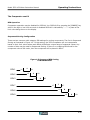
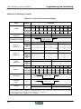
Zero Correction of Parasitic Impedance
"Open Correction" is for the purpose of compensating for the stray capacitance and stray
conductance of cables or test fixtures. Executing an "Open Correction" procedure on the test
leads of fixture before measurement of high impedance DUTs improves measurement accuracy.
"Short Correction" compensates for the residual inductance and resistance of cables or test
fixtures. Performing a "Short Correction" procedure on cables or test fixture before measurement
of low impedance DUTs improves measurement accuracy.
If the condition or position of a cable or test fixture changes, you MUST carry out Zero Correction
to compensate for the change. When performing a Zero Correction, keep hands and metallic
objects away from the cable or fixture.
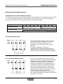
Table 4.2: Short and Open Null Connections
Open Correction
Connection
Terminal
Only
Correct
Short Correction
Incorrect
Correct
Incorrect
G
L
H
G
L
H
G
L
H
G
L
H
G
L
H
G
L
H
G
L
G
L
H
H
5-Terminal
Kelvin
Klips™
LF
HF
LS
HS
LF
HF
LF
HF
LS
HS
LS
HS
Insulator
4-4
LF
LS
HS
HF
Operating Instructions
Model 3550 LCR Meter Instruction Manual
Measurement Tips cont’d:
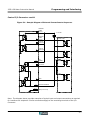
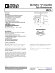
Test Lead Requirements
Four-wire Kelvin-type cables or fixtures must be used with the 3550 in order to obtain accurate
impedance measurements. The Kelvin measurement technique allows significant accuracy
advantage over the two-wire method. This is because it virtually eliminates lead resistance and
inductance and reduces stray capacitance between the source and sense leads.
Two of the four conductors are designated as source leads. These source leads provide the
precision test current that will be referenced in making the resistance measurement. Since current
is the same throughout a series circuit, the lead resistance of the test leads will not have any
effect on the level of reference current.
The other two conductors are designated as voltage sense leads. These leads originate from a high
impedance, volt measurement circuit. When these leads are terminated at the points of contact,
an exact resistance reading is calculated by the 3550’s microprocessor. The series lead resistance
of the voltage sense leads is negligible due to the high impedance of the voltage measurement
circuitry within the 3550.
Figure 4.1a: Four-Wire Kelvin Measurement
ZS
VOLTAGE
SENSE
HSENSE/LSENSE
V
CONTACT
POINTS
ZDUT
REFERENCE
CURRENT SOURCE
HFORCE/LFORCE
ZS
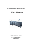
Figure 4.1b: Proper Application of Four Wire Kelvin Measurement
LS
LF
HS
DUT
CORRECT
HF
LS LF
HS HF
DUT
INCORRECT
4-5
Model 3550 LCR Meter Instruction Manual
Operating Instructions
Measurement Tips cont’d:
Measurement Signal Levels
Measurement signal levels are adjustable between 0.01V~5.00V. It is recommended that the
voltage level be kept at a high value (usually 1V or larger) to avoid potential stability problems
associated with test frequency, device impedance and noise.
Series or Parallel Circuit Modes
The "CIRCUIT MODE" should always be "AUTO" mode, unless there is a special circumstance that
requires otherwise. The 3550 is in the AUTO circuit mode when the pushbutton’s LED is
illuminated. Manually setting the circuit mode should only be done in special circumstances where
series or parallel measurement is necessary even if some discrepancy is known to occur.
Auto Range Switching Threshold
When using Auto Range for measurement, the relationship between the switching direction and
indicated switching values are as follows: (When Dissipation Factor: D=0)
Range UP
Range DOWN
When|Z|≥19999 counts
When|Z|≤ 17999 counts
As the dissipation factor, D increases then these threshold values will change.
Display Resolution
The absolute impedance, |Z| of the DUT determines the range of the 3550. All subsequent
measurements will display with a resolution that is consistent with the instrument’s current range
setting.
AC Resistance of Coils with Cores
In most cases the AC resistance of a coil with no core at low frequencies is the same as the DC
resistance. This is not the case for coils with high permeability cores such as ferrite or iron. Higher
permeability will promote core losses from an AC signal causing the resistance measurement to
appear larger than it would be for a DC measured resistance value. Therefore, an inductance
measurement taken at 42Hz (the lowest frequency setting of the 3550) will not necessarily reflect
a DC equivalent resistance value.
4-6
Operating Instructions
Model 3550 LCR Meter Instruction Manual
Front Panel Description
Front Panel Layout
14
16
18
20
22
15
17
12
10
21
11
2
8
6
9
7
13
19
4
5
3
1
Figure 4.2: Front Panel layout
Except for the "POWER" switch, a buzzer will be sounded whenever the function of a switch is
changed.
4-7
Model 3550 LCR Meter Instruction Manual
Operating Instructions
Front Panel Description cont’d:
1 - [POWER] Switch – [POWER]
With the power switch in the down state, power is applied to the 3550 and in the up state power is
off. When the power is turned on, the remaining operational switches will retain the same status
as they had before the power was previously turned off.
If the power is turned on while simultaneously pushing the [MAN/EXT] Key, the machine will
return to its factory default settings.
2 "CIRCUIT MODE" Panel - [AUTO] [SER] [PRL]
This panel contains the keys used for setting the Series or Parallel Equivalent Circuit Mode. When
verifying incoming component values it is usually good practice to consult the manufacturer for the
recommended test mode.
In general, parallel mode is used when the reactance of a device is large. Parallel mode should be
used when a capacitor’s leakage or an inductor’s core losses significantly affects the reading.
Series mode is recommended for small reactance measurements in capacitors and inductors where
series lead resistance must be considered and leakage and core losses become negligible.
•
•
•
[AUTO] – When this key is illuminated, the instrument is in AUTO equivalent circuit mode.
This means that the 3550 will automatically select either series or parallel equivalent circuit
mode based on the impedance of the DUT. It does not necessarily mean that the correct
equivalent circuit mode will be selected.
[SER] – Series equivalent circuit mode is typically desirable for low reactance
measurements. This is because Rs or series resistance becomes more significant than
parallel resistance to the measured value.
[PRL] – Parallel equivalent circuit mode is often more effective for measurement of
impedances with high reactive components. This is because in a capacitor or inductor with
a high reactance, the parallel leakage is more significant to the measured value.
3 "TRIGGER" Panel - [INT] [MAN/EXT]
Select either an internal or external trigger by pressing either the [INT] or [MAN/EXT] key. The
active trigger mode of the 3550 is indicated by an illuminated pushbutton.
•
•
4-8
[INT] - When the [INT] key is pressed, the 3550 operates in the continuous trigger mode.
The instrument automatically takes readings at regular intervals.
[MAN/EXT] – Depressing the [MAN/EXT] key will put the 3550 into manual one-shot trigger
mode, which requires the [MAN/EXT] key to be pressed for each reading.
Model 3550 LCR Meter Instruction Manual
Operating Instructions
Front Panel Description cont’d:
4 “ZERO” Panel – [OPEN] [SHORT]
Performing OPEN and SHORT corrections before making an impedance reading greatly improves
measurement accuracy. Refer to page 4-4, “Zero Correction of Parasitic Impedance” for
connection diagrams and other details regarding these procedures.
•
•
[OPEN] - The OPEN circuit zero correction procedure compensates for stray capacitance
and conductance between test leads/fixture. Pressing the [OPEN] key initiates the open
circuit zero correction procedure. Make sure that the test fixture is in the open state before
performing the OPEN circuit zero correction procedure.
[SHORT] – The SHORT circuit zero correction procedure compensates for residual
resistance and inductance in the test leads/fixture. Pressing the [SHORT] key initiates this
procedure. Make sure that the test fixture is shorted before performing the SHORT circuit
zero correction procedure.
There are three variations of zero correction procedures:
1)
2)
3)
Standard Zero Correction: corrects all frequencies. This process requires several
minutes to step through all of the test frequencies. See 4 (p. 4-9) for details.
Spot Zero Correction, allows up to three user-defined frequencies to be corrected: see
[SHIFT]→[8] (p. 4-14) to define spot frequencies; [SHIFT] →[OPEN] (p. 4-16) for Open
circuit spot correction; & [SHIFT] →[SHORT] (p. 4-16) for short circuit spot correction.
Correction Frequency Limit Mode: allows the user to define a range of test frequencies
to be zero corrected during a standard zero correction.
Refer to [SHIFT] →[ - ] (p. 4-16) and 4 (p. 4-9) for more details.
5 "RANGE" Selection Panel – [AUTO] [DOWN] [UP]
The Range panel is used to select either automatic or manual measurement ranges. If AUTO range
is used to find the correct measurement range and the 3550 is then switched to MANUAL range,
the 3550 will retain the current measurement range.
•
•
•
[AUTO] – Pressing the [AUTO] key will toggle between Auto and Manual Range Modes.
When the 3550 is in the AUTO mode, the pushbutton will be illuminated. When the
instrument is in the manual mode the AUTO pushbutton is not illuminated.
[DOWN] – In the manual mode, pressing the [DOWN] key will lower the range of the
instrument. The [DOWN] key will flash to indicate when the current range is under ranged
and needs to be lowered for a reading to take place. When the [DOWN] key is pressed,
then an audible beeper will sound to indicate that the range has been lowered.
[UP] - In the manual mode, pressing the [UP] key will raise the current range of the 3550.
The [UP] key will flash to indicate when the current range is over ranged and needs to be
raised in order for a reading to take place. When the [UP] key is pressed, then an audible
beeper will sound to indicate that the range has been raised.
4-9
Model 3550 LCR Meter Instruction Manual
Operating Instructions
Front Panel Description cont’d:
6 [SHIFT] Key
The [SHIFT] key has dual functionality. Its primary purpose is to allow access to the secondary
functions of the numeric keys. Its secondary function allows the user to switch from Remote
communications Mode (GPIB or RS-232C Operation) to Local (Front Panel) Operation.
Below is a summary of the secondary functions accessible by pressing the [SHIFT] key and then a
corresponding function key. The secondary function keys are [0]~[9], [OPEN], [SHORT] and [-].
For descriptive convenience, notation such as [SHIFT] → [0] etc will be used to indicate that first
the [SHIFT] Key should be pushed, and then the [0]" Key.
[SHIFT] → [0]: Frequency Set Mode
The 3550 test frequency settings may be programmed from 42.0Hz to 5.00 MHz with a
resolution of three significant digits. If DISPLAY C is set to indicate test frequency and the
3550 is in the Measurement mode, the frequency can be adjusted changed by pressing the
[UP] and [DOWN] keys in the DISPLAY C panel.
Pressing [SHIFT] → [0] will cause the 3550 to enter the frequency set mode.
Entering the Frequency Values
The most significant digit in DISPLAY C will flash indicating that a new value must be
entered. Press a key from [0]~[9] to set the value of the first digit and to proceed to set
the next digit value. Once again, press a key from [0]~[9] and proceed to the next digit.
Set the Decimal Point Location
Once values for all of the three digits have been defined, the decimal point will start to
blink indicating that the decimal point needs to be positioned. Press the [DP] key and
notice that the position of the decimal point will change. Continue to press the [DP] key
until the decimal point is positioned correctly.
Select the Frequency Units
Press either the [CURSOR ►] or [CURSOR ◄] keys repeatedly until one of the frequency
units annunciators (Hz, kHz, or MHz) begins to blink. This indicates that the frequency units
mode is now active. Press the [UNIT] key until the desired frequency units annunciator
starts to blink.
Verify and Set the Frequency
The user can go back and edit any of the previous settings by pressing the [CURSOR ►] or
[CURSOR ◄] keys to access the settings. Verify that all frequency settings are correct and
then press the [ENTER] key. This will store the new frequency settings and return the
instrument back to measurement mode.
4-10
Model 3550 LCR Meter Instruction Manual
Operating Instructions
Front Panel Description cont’d:
[SHIFT] → [1]: Test Voltage Set Mode
*See the Appendix for detailed information concerning the measurement ranges for constant current or constant
voltage modes and for instructions for setting either of these modes.
The 3550 test voltage values may be modified if the open circuit voltage or constant
voltage setting is displayed on DISPLAY C. Constant voltage mode is indicated when the
[CV/CC] and [V] pushbuttons are illuminated. The 3550 is in open circuit voltage mode
when only the [V] key is lit.
The Model 3550 has programmable test voltages from 0.01V~5.00V for test frequencies of
42.0Hz~1.00MHz. For test frequencies above 1.00MHz, the voltage can be adjusted
between 0.01V and 1.00V. Test voltages are adjustable in steps of 0.01V and are displayed
in DISPLAY C to three significant digits. Refer to the Appendix to calculate the maximum
voltage range of the constant voltage mode.
If DISPLAY C is set to indicate test voltage and the 3550 is in the Measurement mode, the
voltage amplitude can be incremented or decremented by pressing the [UP] and [DOWN]
keys in the DISPLAY C panel. If the [UP] and [DOWN] keys are held down the 3550 will
increase the speed at which the voltage is incremented or decremented.
If more dramatic changes are required, then the test voltage must be manually entered by
accessing the 3550’s voltage set mode.
Pressing [SHIFT] → [1] will cause the 3550 to enter the voltage set mode. Below are
instructions to set the test voltage.
Enter the Voltage Values
The most significant digit in DISPLAY C will flash indicating that a new value must be
entered. Press a key from [0]~[9] to set the value of the first digit and to proceed to set
the next digit value. Once again, press a key from [0]~[9] and proceed to the next digit.
Verify and Set the Test Voltage
Once all three digits have been entered, double-check the final voltage value. The values
are changed by pressing the [CURSOR ►] or [CURSOR ◄] keys and entering a new value.
Press the [ENTER] key to save the voltage setting and to return back to the measurement
mode.
If a programmed voltage exceeds the instrument’s sourcing capability, the 3550 will beep
three times and not allow the illegal value to be saved if the [ENTER] key is pressed.
[SHIFT] → [2]: Test Current Set Mode
*See the Appendix for detailed information concerning the measurement ranges for constant current or constant
voltage modes and for instructions for setting either of these modes.
The 3550 test current values may be modified if the open circuit current or constant
current setting is displayed on DISPLAY C. Constant current mode is indicated when the
[CV/CC] and [I] pushbuttons are illuminated. The 3550 is in open circuit current mode
when only the [I] key is lit.
Programmable test currents are available from 0.01mA~99.99mA for test frequencies of
42.0Hz~1.00MHz. For test frequencies above 1.00MHz, the current can be adjusted
between 0.01mA and 20.00mA. The 3550’s test current is adjustable in 0.01mA steps and
is displayed to three significant digits. Refer to the Appendix for instructions to calculate
the maximum test current available in the constant current mode for a given impedance.
4-11
Model 3550 LCR Meter Instruction Manual
Operating Instructions
Front Panel Description cont’d:
[SHIFT] → [2]: Test Current Set Mode cont’d:
If DISPLAY C is set to indicate test current and the 3550 is in the Measurement mode, the
current amplitude can be incremented or decremented by pressing the [UP] and [DOWN]
keys in the DISPLAY C panel. If the [UP] and [DOWN] keys are held down the instrument
will increase the speed at which the current is incremented or decremented.
The test current can be manually entered by accessing the instrument’s current set mode.
Below are instructions to manually set the test current.
Enter the Current Values
Press [SHIFT] → [2] to enter the current set mode. The most significant digit in DISPLAY C
will flash indicating that a new value must be entered. Press a key from [0]~[9] to set the
value of the first digit and to proceed to set the next digit value. Once again, press a key
from [0]~[9] and proceed to the next digit.
Verify and Set the Test Current
Once all three digits have been entered, double-check the final current value. Any of the
digits may be accessed and modified by pressing the [CURSOR ►] or [CURSOR ◄] keys and
entering a new value. Press the [ENTER] key to save the current setting and to return back
to the measurement mode. The 3550 will beep three times and will not return to
measurement mode if a programmed test current exceeds the instrument’s sourcing
capability.
[SHIFT] → [3]: Averaging Set Mode
You can define the number of measurements the 3550 makes before it produces a readable
measurement. Averaging is used to stabilize the output reading and to increase the
accuracy of a reading. To set the number of averages per reading, press [SHIFT] → [3].
The active average setting will be displayed on DISPLAY B. The first digit will flash
indicating that one of the numeric keys, [0]~[9] must be pressed to set the value of the
first digit. Once a value has been entered then the next digit will flash. Enter the desired
values for the three digits and press the [ENTER] key to store the new setting. The number
of averages may be set from 1~100 readings. If an illegal value is attempted the
instrument will beep three times when the [ENTER] key is pressed to indicate that the
attempted value is outside of the instrument’s acceptable range.
[SHIFT] → [4]: Key Lock Mode
In the Key Lock mode, all front panel keys except the [SHIFT]" Key, [4] Key, and (in the
case that the Measurement Trigger is set to Manual) the [MAN/EXT] Key will be locked.
The Key lock mode is used to protect the 3550 settings from unintentional changes.
To access the Key Lock Mode settings, press the [SHIFT] → [4] keys. A single digit, either a
“1” or a “0” will be displayed in DISPLAY B. Set the digit to “1” to lock the front panel or to
“0’ to unlock the front panel keys. Press the [ENTER] key to finalize the setting.
4-12
Operating Instructions
Model 3550 LCR Meter Instruction Manual
Front Panel Description cont’d:
[SHIFT] → [5]: Comparator Buzzer Function
Press the [SHIFT] → [5] keys to enter the Buzzer Settings Mode. The active setting, 0~2
will blink in DISPLAY B.
Buzzer Function
Buzzer OFF
GO = Buzzer ON
NO-GO = Buzzer ON
Value
0
1
2
Press either [0], [1] or [2]. The new entry will appear in DISPLAY B. Press [ENTER] to
finalize the setting and to return to the measurement mode.
[SHIFT] → [6]: Trigger Delay Time
The trigger delay time is programmable from 0~10,000 milliseconds (10s). It is used to
add a time delay immediately after the detection of a trigger signal from either the
[MAN/EXT] key, external control device (I/O Control Connector), RS-232C or GPIB
Interfaces.
In the Trigger Delay Time Settings Mode, the active setting for the trigger delay time will
appear flashing on DISPLAY B. The default setting for the Trigger Delay Time is “00000 ms”
The active flashing number can be changed by highlighting the active digits by pressing the
[CURSOR ►] or [CURSOR ◄] keys and entering a new value by pressing the [0]~[9] keys.
When all the necessary digits have been changed press the [ENTER] Key to finalize the
settings and return to Measurement mode.
4-13
Model 3550 LCR Meter Instruction Manual
Operating Instructions
Front Panel Description cont’d:
[SHIFT] → [7]: Comparator Functions Mode
Press [SHIFT] → [7] to access the Comparator Functions Mode. Either a flashing “0” or a “1”
will appear on DISPLAY B. The meaning of the numbers is as follows:
0: Absolute Value Comparator Function
1: Percent Comparator Function
To change the flashing digit, press either [0] or [1] and press [ENTER] to store the new
setting and return to the measurement mode.
[SHIFT] → [8]: Defining Spot-Correction Frequencies for Zero Adjustments
The spot-correction frequency mode allows the user to identify up to three specific test
frequencies where open and short-circuit, zero adjustments may be performed. This
feature condenses the default zero adjustment procedure by limiting the zero adjustments
to user-defined frequency points instead of stepping through the entire range of test
frequencies (42Hz~5MHz). Performing spot-correction frequency zero adjustment saves
time by eliminating the zero adjustment of unused test frequencies.
Select the Spot Frequency Number
Press [SHIFT] → [8] to enter the spot-correction frequency editing mode. The BIN LED will
display a flashing “1”, “2”, or “3”. Press either the [1], [2], or [3] keys to select the spot
frequency you would like to set.
Entering the Spot Frequency Value
Once a key is pressed, DISPLAY C will display “---“ indicating that a spot frequency must be
defined. Press the [0]~[9] keys to enter the spot frequency digits. Next, press the [DP] key
to position the decimal point. Press either of the [CURSOR ►] or [CURSOR ◄] keys to
highlight the frequency units. Press the [UNIT] key until the desired frequency units
annunciator starts to blink. Press the [ENTER] key to finalize the spot frequency setting.
To disable the Spot Correction Frequency, make sure that you are in the spot frequency
editing mode (press [SHIFT] → [8]) use the [CURSOR] keys to highlight DISPLAY C. When
this is done, press the [IGNORE] key to erase the current spot frequency setting.
4-14
Operating Instructions
Model 3550 LCR Meter Instruction Manual
Front Panel Description cont’d:
[SHIFT] → [9]: RS-232C Settings Mode
For the RS-232C, the baud rate, data length, parity and stop bit can be defined by the
user. Press the [SHIFT] → [9] key to enter into the RS-232C setup mode.
After entering the RS-232C setup mode, you will notice that the BIN LED will begin to blink.
Press a key from [1] ~[4] to select the RS-232C parameter that you wish to set.
[1]:
[2]:
[3]:
[4]:
Set
Set
Set
Set
the
the
the
the
Baud Rate
Data Length
Parity
Stop Bit
Default=5,
Default=1,
Default=0,
Default=0,
9600BPS
8 Bits
No Parity
1 Stop Bit
Notice that after selecting a parameter from 1-4, DISPLAY B will show a number that
corresponds to the parameter setting as summarized in the tables below: Use the tables to
determine the appropriate setting for the RS-232C communications. Use the [CURSOR ►]
or [CURSOR ◄] keys to navigate between the RS-232C parameter and the setting on
DISPLAY B.
Press the [ENTER] key to finalize the settings and return to measurement mode.
BIN Display "1" Baud Rate Settings
DISPLAY
Settings
B
RS-232C Settings
BIN Display "3"
Parity Settings
DISPLAY B
Settings
RS-232C
Settings
0
300bps
1
600bps
0
No parity
2
1200bps
1
Odd parity
3
2400bps
2
Even parity
4
4800bps
5
9600bps
6
19.2kbps
7
38.4kbps
BIN Display "4" Stop Bit Settings
BIN Display "2"
Settings
Data Length
DISPLAY B
Settings
RS-232C
Settings
0
7bits
1
8bits
DISPLAY B
Settings
RS-232C
Settings
0
1bit
1
2bit
4-15
Model 3550 LCR Meter Instruction Manual
Operating Instructions
Front Panel Description cont’d:
[SHIFT] → [-]: Correction Frequency Limit Setting Mode
As an alternative to zero correcting the entire frequency range 42Hz~5MHz, this function
allows the user to set the correction frequency range in terms of upper and lower limits.
Press [SHIFT] → [-] to enter the Correction Frequency Setting Mode. The “BIN” LED will be
flashing. Press either [1] to edit the low limit correction frequency or [2] to edit the high
limit correction frequency.
Use the [CURSOR ►] or [CURSOR ◄] keys to navigate between the “BIN” LED, DISPLAY C
Digits, Decimal Point and Frequency Units. To change the frequency value indicated on
DISPLAY C, simply press the [0]~[9] keys.
Press the [DP] key to change the position of the decimal point and use the [UNIT] key to
select Hz, kHz, or MHz units.
Press the [ENTER] key in order to finalize the new setting and to return to measurement
mode.
NOTE: While in the Spot Correction Frequency Mode, the Spot Correction Frequency high or
low limit setting can be enabled or disabled. This is done by pressing the [IGNORE] key.
[SHIFT] → [OPEN]: Spot Correction Mode (Open Correction)
The spot correction Mode is used for making open and short-circuit frequency corrections.
Pressing the [SHIFT] → [OPEN] keys will allow an open circuit, spot frequency correction to
take place. The open circuit correction is performed only on the three spot frequencies that
are defined by pressing [SHIFT] → [8], (see Defining Spot-Correction Frequencies for Zero
Adjustments).
Note that Spot Frequency Zero Corrections have precedence over Normal Zero Corrections.
This means that the open and closed-circuit, zero correction factors for the spot frequencies
will be stored and retained in the instrument’s memory and will be written over unless an
additional spot frequency correction procedure is performed. Performing a standard zero
correction procedure will write over the zero adjustment factors of all test frequencies
except the three user-defined, spot correction frequencies.
[SHIFT] → [SHORT]: Spot Correction Mode (Short Correction)
Pressing [SHIFT] → [SHORT] initiates the Short-Circuit, Spot Frequency Correction
process. The offset adjustment affects only the three user-defined Spot Correction
Frequencies discussed in the, Defining Spot-Correction Frequencies for Zero Adjustments
section ([SHIFT] → [8]).
Like the Open Circuit Spot Frequency Correction Mode, Short Circuit Spot Corrections have
precedence over Normal Short Circuit Zero Corrections. Closed circuit, spot correction
factors will be stored and retained in the instrument’s memory and cannot be written over
unless an additional spot frequency correction procedure is performed. Performing a
standard zero correction procedure will write over the zero adjustment factors of all test
frequencies except the three user-defined, spot correction frequencies.
4-16
Operating Instructions
Model 3550 LCR Meter Instruction Manual
Front Panel Description cont’d:
7 “UNKNOWN" Terminals Panel
Four BNC-type terminals plus one GUARD are available for making shielded or unshielded Kelvintype measurement connections to the DUT. Their designations and functions are summarized
below:
Table 4.3 – Unknown Terminals
Connection
Type/Description
Measurement Function
BNC LFORCE
BNC LSENSE
BNC HFORCE
BNC HSENSE
Binding Post GUARD
Low Side Current Source
Low Side Voltage Sense
High Side Current Source
High Side Voltage Sense
Five-wire shielded measurements
8 "COMPARATOR LIMIT SET" Panel - [CURSOR ►] [CURSOR ◄] [LOW] [HIGH]
When programming comparator settings, the keys in the Comparator Limit Set Panel are used to
define the DISPLAY A & DISPLAY B Comparator values. The two left most keys are the [CURSOR
►] or [CURSOR ◄] keys. In the comparator set mode, these cursor keys allow navigation between
the present BIN number (1-9) and DISPLAY A and DISPLAY B comparator value settings.
If a value is defined for either DISPLAY A or DISPLAY B (by pressing digits [0]~[9] while the
DISPLAY digits are blinking.) then the functionality of the [CURSOR ►] or [CURSOR ◄] keys
extends to allow navigation of the comparator value’s decimal point location and selection of the
DISPLAY A and DISPLAY B units of measure.
The Comparator's High and Low Limit Values for DISPLAY A and DISPLAY B can be set by pressing
the [LOW] and [HIGH] Keys while in the measurement mode. Pressing either of these keys will put
the 3550 into the Comparator Limits Set Mode.
Once in the Comparator Limits Set Mode, the BIN# and values for DISPLAY A and DISPLAY B
comparator settings can be defined by using the secondary functions (blue text) of the keys
located in the CIRCUIT MODE, RANGE, DISPLAY C, and DISPLAY A-B Panels. These secondary
functions include [0]~[9], [-], [D.P.], [UNIT], and [IGNORE] commands.
NOTE: Only panels 1~9 can have comparator limit values assigned to them.
9 The "GUARD" Terminal
This terminal is connected to the chassis of the 3550. When measuring High-Impedance devices,
connect the device’s shield to this binding post.
4-17
Model 3550 LCR Meter Instruction Manual
Operating Instructions
Front Panel Description cont’d:
10 Remote Interface Status LEDs – “SRQ” “LTN” “TLK” “RMT”
These LEDs indicate the status of remote communications using the 3550’s standard RS-232C and
optional GPIB (IEEE-488.2) interfaces
All four annunciators are used for GPIB communications. If the RS-232C is the controller, then
only the "RMT" LED is used.
11 "PANEL" Selector Switch
Pressing the [0-9] key in the Panel section allows the user to select a preset panel setting from 09. Each consequent press of the [0-9] key will increment to the next preset panel number. The
active instrument settings are automatically updated to the panel number indicated on the seven
segment LED (Panel Display LED). If the instrument settings are changed while a panel number
(0-9) is active and the panel key is pressed then the existing settings will be stored into the panel
location indicated by the Panel Display LED.
Only panels 1~9 can have comparator limit values assigned to them.
12 "PANEL" Display LED
The PANEL Display LED is a seven segment LED that displays the active panel setting.
Press the [0-9] key located in the Panel Section to increment through panel settings 0-9.
13 "DISPLAY A" Parameter Selection Key - [A]
Press this key to select the measurement parameter of DISPLAY A. Measurements of L, C, R, |Z|
and |Y| are available.
14 "DISPLAY A"
Measured values of L, C, R, |Z|, and |Y| are shown in this panel. The measurements values range
from 0000 to 19999 and are displayed with 41/2 - digit resolution. In addition, units of measure are
annunciated above and beside the display for reading convenience.
To change the parameters shown by DISPLAY A, press the [A] key located in the DISPLAY A-B
instrument panel until the desired measurements are shown.
15 "BIN" Display LED
The BIN Display LED is a seven segment LED that displays the active sorting bin number of the
Comparator. When the Comparator is ON, this LED displays which BIN Number the present
measurement is associated with. "1" through "9" are for OK products, while "0" is reserved for
defects such as open circuit conditions.
4-18
Model 3550 LCR Meter Instruction Manual
Operating Instructions
Front Panel Description cont’d:
16 Comparator State Annunciators
Located in the Comparator Panel there are three total comparator state annunciators. The
annunciators become active when the comparator is on. The comparator is turned on by pressing
the [ON] key in the Comparator Panel. See below for a summary of the annunciator functions.
Annunciator
DISP-A LO-HI
DISP-B LO-HI
TOTAL GO
Functional Description
Indicates when the measured value of DISPLAY A is equal to or outside of the
Low or High Comparator setting.
Indicates when the measured value of DISPLAY B is equal to or outside of the
Low or High Comparator setting.
Indicates when the measured value of DISPLAY A and DISPLAY B are within
the High and Low limits of the Low or High Comparator setting. If DISPLAY A
comparator is disabled then the TOTAL GO DISPLAY B determines condition
only. If DISPLAY B comparator is disabled then the TOTAL GO condition is
determined by DISPLAY A only.
17 Sample LED (Trigger Status)
This LED displays the measurement status. When the TRIGGER mode is set to "INT", this LED will
flash continuously. When the TRIGGER mode is set to "MAN/EXT", this LED will flash every time a
measurement is made.
18 "COMPARATOR ON/OFF" Switch – [ON]
This switch enables or disables the Comparator. When the switch is in the ON state (LED on), the
BIN Display LED, Comparator State Annunciators, and Comparator functions are enabled.
19 "DISPLAY B" Parameter Selection Key - [B]
Press this key to select the measurement parameter of DISPLAY B. Measurements of D, Q, RS, RP,
G, X, B and θ are available.
20 "DISPLAY B"
Measured values of D, Q, RS, RP, G, X, B and θ are shown in this panel. The measurements values
are displayed with 41/2 - digit resolution. In addition, units of measure are annunciated above and
beside the display for reading convenience.
To change the parameters shown by DISPLAY B, press the [B] key located in the DISPLAY A-B
instrument panel until the desired annunciator is lit.
4-19
Model 3550 LCR Meter Instruction Manual
Operating Instructions
Front Panel Description cont’d:
21 DISPLAY C Measurement Panel – [FREQ] [ V ] [ I ] [CV/CC] [DOWN] [UP]
The keys on the DISPLAY C Measurement panel are used to set the measurement frequency,
constant voltage, voltage or constant current mode, test signal amplitude and the measurement
that will be shown on DISPLAY C.
[FREQ] – Test Frequency Select Key
When [FREQ] is pressed, the test frequency will be shown on DISPLAY C. The displayed
test frequency setting can be adjusted using the [DOWN] and [UP] Keys to increment or
decrement the existing test frequency setting. To define the test frequency value, decimal
point location and units refer to the [SHIFT] → [0]: Frequency Set Mode section.
[V] – Show Test Voltage on DISPLAY C
When the [V] key is pressed the test voltage will be shown on DISPLAY C. Pressing either
the [UP] or [DOWN] keys will adjust the test voltage. The test voltage, decimal point and
units can be set by using the [SHIFT] → [V] key sequence.
The Model 3550 has programmable test voltages from 0.01V~5.00V for test frequencies of
42.0Hz~1.00MHz. For test frequencies above 1.00MHz, the voltage can be adjusted
between 0.01V and 1.00V. Test voltages are adjustable in steps of 0.01V and are displayed
in DISPLAY C to three significant digits.
When in the constant voltage mode, and the [UP] or [DOWN] keys are pressed, DISPLAY C
will momentarily show the open circuit test voltage setting before displaying the constant
voltage applied to the actual test device terminals. If either the [UP] or [DOWN] key is
pressed and held, the voltage setting will display and the setting will either scroll up or
down (depending on whether the [UP] or [DOWN] key is pressed.
[I] – Show Test Current on DISPLAY C
When [I] is pressed, the test current flowing through the DUT will be displayed. Pressing
either the [UP] or [DOWN] keys will adjust the test current level. The test current, decimal
point and units can be set by using the [SHIFT] → [I] key sequence.
Programmable test currents are available from 0.01mA~99.99mA for test frequencies of
42.0Hz~1.00MHz. For test frequencies above 1.00MHz, the current can be set between
0.01mA and 20.00mA. The 3550’s test current is adjustable in 0.01mA steps and is
displayed to three significant digits.
When in the constant current mode, and the [UP] or [DOWN] keys are pressed, DISPLAY C
will momentarily show the open circuit test voltage setting before displaying the actual
current flowing through the test device. If either the [UP] or [DOWN] key is pressed and
held, the voltage setting will display and the setting will either scroll up or down (depending
on whether the [UP] or [DOWN] key is pressed.
4-20
Operating Instructions
Model 3550 LCR Meter Instruction Manual
Front Panel Description cont’d:
Test Signal Modes - [CV/CC]
Model 3550 is capable of three different measurement modes. These are Open Circuit Test
Voltage Mode, Constant Voltage Mode, and Constant Current Mode. The active
measurement mode can be confirmed by looking at the [V], [I], and [CV/CC] LED Keys in
the DISPLAY C panel.
The relationship between the operation modes and the LED displays are as follows:
Table 4.4 – CV/CC Indicators
Open Circuit Test Voltage Mode
[V]
LED
ON
[I]
LED
OFF
[CC/CV]
LED
OFF
Constant Voltage Mode
ON
OFF
ON
Constant Current Mode
OFF
ON
ON
Measurement Mode
Set Voltage Mode
Measurements are taken using the open circuit Test Voltage. The test voltage varies with
current. Use this mode for ordinary test objects that possess an overall impedance value
with real and imaginary components.
Constant Voltage Measurement Mode
This makes the measurement while keeping the voltage of the measurement terminals at a
fixed level. For example, this mode can be used for testing inductors where terminal
voltage will vary. Using Constant Voltage mode can help stabilize a reading.
Constant Current Measurement" Mode
This makes the measurement stable by keeping the current passing through the DUT at a
fixed level. For example, this mode can be used for testing capacitors where test current
continuously varies with applied voltage.
22 "DISPLAY C"
Displays Frequency (Hz, kHz, and MHz), Open Circuit Test Voltage (V), Terminal Voltage (Constant
V), and DUT Test Current (Constant mA) based on the settings of the DISPLAY C Measurement
Panel. The measurement values are displayed with 41/2 - digit resolution. Units of measure are
annunciated beside the display for reading convenience.
23 ENTER Key – [ENTER]
Used in the various programming modes to finalize user-defined instrument settings. For example,
the [ENTER] key is pressed to finalize any of the [SHIFT] → [0~9] commands and to return back
to the measurement mode.
4-21
Operating Instructions
Model 3550 LCR Meter Instruction Manual
Rear Panel Description
Figure 4.3 - Rear Panel Layout
Line Voltage
Selector Plug
GPIB Board
Slot
Fuse Rating
Chart
RS-232C Port
Fuse Input
VAC Input
GND Terminal
Line Voltage Selector Plug – The Model 3550 is
capable of 100/120/220/240 VAC 50/60 Hz Operation. To
change the line voltage, remove the plug by pulling it
from the rear panel. Put the plug back in to the socket
with the arrow pointing to one of four supply voltage
settings.
Fuse Input – Use 3AG Type Fuses, ¼” X 1¼”
(6.35X31.75mm)
Fuse Rating Chart - See Rear Panel or Preparation for
Use Section for fuse ampere ratings. Use fast acting fuses
only.
VAC Input – 100/120/220/240, power input. An internal
line filter is included in this input.
GND Terminal – The GND binding post provides a direct
connection to the instrument’s chassis and the grounded
connector of the VAC input plug.
4-22
Cooling Fan
Ventilation
Holes
Control I/O
Port
Cooling Fan Ventilation Holes – To prevent
overheating, keep these ventilation holes free of
obstructions. Periodically inspect these holes to assure
they are free of obstructions.
Control I/O Port – The Control I/O Port has optically
isolated TTL inputs and outputs used for remote
operation. Inputs include BCD Panel Selection and trigger
inputs. Outputs include A, B and total Comparator
outputs, End of measurement, BIN, Busy and Error
Outputs. The control connector also includes pins for
external power connections.
RS-232C Port – Standard RS-232C Port.
GPIB Board Slot – Slot provided for factory installed
GPIB (IEEE-488.2) option PN# 3505.
Operating Instructions
Model 3550 LCR Meter Instruction Manual
Making Accurate Measurements:
Connections to the Device Under Test (DUT)
The relationship between the connections schemes and impedance, |Z| ranges are shown in Table
5-1. It is extremely important, for measurement accuracy purposes, to observe appropriate
connection methods for the subject test piece and measurement range.
Range
1
2
3
4
Low Impedance
(Series Equivalent Mode)
6
7
8
9
High Impedance
(Parallel Equivalent Mode)
3 Terminal Connection
5 Terminal Connection
Impedance Mode
Connection Type
5
3-Terminal Measurement
GUARD
LFORCE
LSENSE
HSENSE
HFORCE
This measurement method is used for testing
devices having high impedance. In general,
components with large inductance, low
capacitance, or high resistance fall into this
category.
The major advantage to 3-terminal
measurements is that the influence of stray
capacitance and conductance between the test
leads and nearby conductors becomes negligible.
DUT
4 or 5-Terminal Measurements
GUARD
LFORCE
LSENSE
DUT
HSENSE
HFORCE
The 5-terminal measurement method can be
used for all impedance ranges and has significant
advantage over the 3-terminal measurement
method. The advantage is that in addition to
canceling the effects of stray capacitance and
conductance between the measurement leads
and close proximity conductors, the residual
inductance and resistance of the test lead are
bypassed by placing the voltage sense points of
contact directly at the DUT terminals.
A four-terminal measurement is the same as a
five-terminal measurement except that the guard
connection is not used.
4-23
Operating Instructions
Model 3550 LCR Meter Instruction Manual
Making Accurate Measurements:
Test Fixture Selection
Model 3510 Radial/Axial Lead Adapter
The Model 3510 Radial/Axial Lead adapter is a
general-purpose accessory used for testing
components with radial or axial leads. Components
are tested by plugging the leads directly into the
adapter sockets.
The Model 3510 is designed for 5-terminal
measurements and is capable of measuring a wide
range of impedances.
Model 47454 Kelvin Klips™
Model 47454 Kelvin Klip Leads are designed for 5wire, Kelvin measurement of all types of component
styles. They may be used for both low and high
impedance measurements.
Kelvin Klips are particularly convenient for low
impedance test devices or components with short
leads, however, the measurement frequency and
impedance range are limited as shown in Table 4.4.
Exceeding the recommended measurement ranges
may result in erroneous and inaccurate readings.
Table 4.4 - Impedance and Frequency Limitations of Kelvin Klip Leads
Frequency
42Hz ~ 10kHz
10.1kHz ~100kHz
101kHz ~ 1.00MHz
Measurement Range
100mΩ ~ 1MΩ
1Ω ~ 100kΩ
10Ω ~ 10kΩ
NOTE: Additional test voltage and current restrictions of the 3550 unrelated to test fixtures apply for
measurements exceeding 1MHz.
4-24
Operating Instructions
Model 3550 LCR Meter Instruction Manual
Making Accurate Measurements cont’d:
Test Fixture Selection cont’d
Model 3511 Surface Mount Device (SMD) Test Fixture
The 3511 is a test fixture designed to perform 3-wire
impedance measurements of surface mount devices.
This adapter is suitable for measurement of chip
components with middle to high impedance ranges.
The measurement frequency and range limitations
are summarized in table 4.5 below
Exceeding the recommended measurement ranges
may result in erroneous and inaccurate readings.
The signal level limitations of the instrument must
also be considered when making measurements
above 1MHz.
Table 4.5 - Impedance and Frequency Limitations of the SMD Test Fixture
Frequency
42Hz ~ 100kHz
101kHz ~1.00MHz
Measurement Range
10Ω ~ 1MΩ
10Ω ~ 10kΩ
10Ω ~ 10kΩ
1.01MHz ~ 5.00MHz
(10Ω Minimum)
Model 2005B Chip Component Tweezers
2005B is designed for manual sorting of chip
components from DC to 1MHz. Four-terminal
tweezers make solid connections on chips up to
0.50 in. (12.7mm) long. The set includes a 5 ft.
(1.5m) cable for connection to the 3550
47422 – Chip Tweezer Rebuild Kit
Tweezer tips are intended to last from 100,000 to
500,000 operations. This tip replacement kit
includes 12 replacement tips, 2 screws, and 1
wrench.
4-25
Operating Instructions
Model 3550 LCR Meter Instruction Manual
Making Accurate Measurements cont’d:
Zero Corrections
Residual Impedance and Leakage of test fixtures exists for all types of test fixtures. To maintain
the performance accuracy of the 3550 it is highly recommended that a zero correction be
performed whenever a change in test fixture takes place. For test fixtures such as Kelvin Klip
Leads where the positioning may vary, extra effort must be made to perform the zero correction
while positioning the leads in the exact location, as the measurement will be taken.
When performing a standard zero correction, the instrument will step through frequencies from
42Hz to 5MHz. This takes a considerable amount of time and may not be desired in certain
applications especially when the actual component test will take place at a single frequency point.
To overcome this, the 3550 has the ability to perform spot frequency corrections where zero
corrections are performed on up to three user defined frequency set points. The spot frequency
zero correction data is stored in the instrument’s non-volatile RAM and will overwrite any
correction data obtained from a standard zero correction procedure. A standard zero correction
cannot write over data from a spot frequency zero correction. The spot frequency setting must be
disabled in order for the standard zero correction to be able to write over all frequency points.
Refer to “Defining Spot-Correction Frequencies for Zero Adjustments”, [SHIFT] → [8] in the front
panel description to learn how to enable or disable the spot frequency settings.
Table 4.6 - Zero Correction Limits
Zero Correction
Correction
Correction Limit
Open
Stray Capacitance & Stray Conductance
(C0)&(G0)
>1kΩ
Short
Residual Inductance & Residual Resistance
(L0)&(R0)
< 1kΩ
If during OPEN correction the Impedance is less than 1kΩ, or during SHORT correction the
Impedance is 1kΩ or higher, a buzzer will go off to warn that correction cannot be made, and
the system will reset without making the correction.
There are three methods of defining what frequencies a zero correction will be performed on. They
are Standard, Frequency Limit, and Spot Frequency Zero Correction.
Standard Zero Correction
Refer to Section 4 , “ZERO” Panel – for instructions to perform a standard open and short circuit
correction. This procedure will perform a zero correction on all test frequencies, 42Hz~5MHz
except for those designated as spot correction frequencies.
Frequency Limit Zero Correction
For zero correction, [SHIFT] → [-], Correction Frequency Limit Setting Mode allows the user to
define the upper and lower frequency limits instead of using the default 42Hz~5MHz range.
Spot Frequency Zero Correction
Refer to [SHIFT] → [OPEN] and [SHIFT] → [SHORT] sections for instructions to perform a spot
frequency open and short zero correction procedure.
After performing the zero correction procedure, perform a “before and after” measurement on a
component with an accurately known value to confirm that a zero correction has taken place. A
calibrated capacitance or inductance standard would be ideal (but not required) for this type of
verification.
4-26
Operating Instructions
Model 3550 LCR Meter Instruction Manual
Making Accurate Measurements cont’d:
Zero Corrections cont’d
NOTE: The parasitic impedance of test adaptors and measurement cables differ from cable to
cable. Whenever a test adaptor or cable is changed, make sure that zero correction is performed
again.
Figure 4.4 - Terminal Connections for Zero Correction
Connection
Open Correction
Normal
Error
Short Correction
Normal
Error
G
L
H
G
L
H
G
L
H
G
L
H
G
L
H
G
L
H
G
L
H
G
L
H
BNC
Terminals
5-Terminal
Correction
Kelvin Klip™
Correction
LF
HF
LF
HF
Ls
Hs
Ls
Hs
LF
HF
LF
HF
Ls
Hs
Ls
Hs
Use Figure 4.4 as a reference when performing short-circuit and open-circuit zero corrections.
4-27
Model 3550 LCR Meter Instruction Manual
Operating Instructions
Making Accurate Measurements cont’d:
Equivalent Circuits
The DUT can be described in terms of Impedance (Z) or Admittance (Y). The relationships of the
various characteristics are as follows:
Z = R + jX
Y = G - jB =
D=
R
G
=
X
B
Q=
1
D
1
Z
XL = ωL = 2πfL
XC =
1
1
=
ωC 2πfC
θ = tan-1
X
R
= tan-1 B
G
Z : Impedance
R : Equivalent Resistance
X : Reactance (jX)
Y : Admittance
G : Conductance
B : Susceptance (jB)
D : Loss Coefficient
Q : Quality
θ : Phase Angle
f : Measurement Frequency Hz
ω : Measurement Frequency rad/s
The measurable quantities of the 3550 are L, C, R, Z, Y, D, Q, G, Rp, Rs, X, B, and θ. The
measured value of these parameters will change in value as the test frequency is increased or
decreased. These measured parameters are said to be dependent upon test frequency.* Two
examples are capacitive reactance, which is inversely proportional to frequency and inductive
reactance, which is inversely proportional to frequency. Because of the direct relationship to test
frequency, related quantities such as Dissipation Factor and Quality Factor is also frequency
dependent.
*In measurement applications, the measured R and G values will change with frequency. True R
and G are not theoretically dependent to frequency but in LCR measurement applications, parallel
leakage and series losses can affect the measured R and G value of the component. Compensation
for these errors is the reason for Series and Parallel Equivalent Circuit Measurement Modes.
In general, parallel leakage becomes significant in highly reactive (small capacitors or large
inductors) measurements and series resistance is more significant in low reactance (large
capacitors and small inductors) measurements. This is the reasoning behind the use of series or
parallel equivalent circuit measurement modes.
If the dissipation factor, D is small then the difference between Series Equivalent and Parallel
Equivalent Circuit Measurement Mode measurement will be small. As the dissipation factor
increases, the difference between parallel and series equivalent measurements will increase. Thus,
precautions must be taken when performing measurements on components with high dissipation
factors.
4-28
Operating Instructions
Model 3550 LCR Meter Instruction Manual
Making Accurate Measurements cont’d:
Equivalent Circuits cont’d
Table 4.7 Illustrates the effects of leakage and series resistance on component measurements. It
also provides some additional formulae to illustrate the relationship that dissipation factor has on a
device’s impedance measurement.
Table 4.7 – Equivalent Circuit Relationships
Equivalent
Dissipation Factor
Circuit
(D)
Conversion Formula
Mode
(SER)
Ls
L
R
(
1
R
D=
=
ωLS Q
)
LP = 1 + D ⋅ LS
2
G=
D2 1
⋅
1 + D2 R
(PRL)
G
1
Q
LS =
1
⋅ LP
1 + D2
R=
D2 1
⋅
1 + D2 G
1
D = ωCSR =
Q
CP =
1
⋅ CS
1 + D2
G=
D2 1
⋅
1 + D2 R
G
1
D=
=
ωCP Q
CS = 1 + D ⋅ C P
(
D2 1
R=
⋅
1 + D2 G
D = ωLPG =
LP
(SER)
Cs
C
R
(PRL)
G
CP
2
)
The Series Equivalent Circuit Mode of the 3550 can be used for testing devices where series
impedance has a great effect on the measurement. Parallel Equivalent Circuit Mode is used for
testing devices with high reactance where parallel leakage becomes more significant. The formulae
in Table 4.7 can be used to convert readings in one equivalent circuit mode to the other.
Note that the measured value of D (or Q) will not be different whether it is measured in Series or
Parallel Equivalent circuit mode.
4-29
Model 3550 LCR Meter Instruction Manual
Operating Instructions
Operating the 3550
Preparation
Check the Power Source Voltage. The voltage range of this machine is displayed on the rear of
the machine. The power voltage may be selected using the switching plug on the rear panel. See
“Preparation for Use” for more setup details.
When the [POWER] Switch is turned ON the settings of the machine will be same as when the
power was previously turned off. In order to reset the 3550, simply press [MAN/EXT] at the same
time the [POWER] key is pressed. Resetting will clear the zero correction factors and return the
instrument settings to factory defaults. A table summarizing the factory default settings can be
found in Chapter 3, Quick Start Instructions.
How to Perform a Zero Correction
Determine whether test leads, an adapter or some other fixture will be used to make
measurements and connect it to the front panel BNC terminals. Perform a Standard, Frequency
Limit, or Spot Frequency Zero Correction for both open and closed circuit conditions. To perform a
standard zero correction, follow the instructions below:
a) With the tips of the test leads or the adapter in an "open" condition, push the [OPEN]
switch. DISPLAY A will show “OP–57” to indicate that an open correction is being
performed and “57” will indicate what step frequency the instrument is adjusting for.
The instrument will count down from “57” to “1”. Do not touch or adjust the test
leads/fixture while the zero correction procedure is taking place.
b) Once the “OPEN” correction is completed the unit will return to the measurement mode.
Connect the test leads/fixture in the "shorted" position (see Figure 4.X) and press the
[SHORT] key. The instrument will execute the short circuit correction procedure.
During the Open or Short Circuit Zero Correction process, if the Correction Value min/max
threshold is exceeded, a warning buzzer will sound 3 times to warn that the correction could not
be done. If this happens, lower the parasitic Impedance, and re-do the correction. If the test
leads/fixture continue to fail the zero correction, double check that the operating frequency range
of the leads/fixture have not been exceeded. See “Test Fixture Selection” to determine whether
the test frequency range of your test leads/fixture have been exceeded and whether a Frequency
Limit or Spot Frequency Zero Correction need to be performed instead of a Standard Zero
Correction. Frequency Limit and Spot Frequency Zero Corrections allow the user to define the
specific frequencies to be open and short compensated. Frequency Limit and Spot Frequency
Corrections can also be used to shorten the total zero correction time by ignoring unused test
frequencies.
If the proper frequency correction has been performed and the test leads/fixture continues to fail
zero correction, have the leads/fixture tested by an authorized service person.
!
Detailed instructions for performing "open " or "short” circuit zero corrections are found in the
“Measurement Tips” and in “Front panel Description” sections of this manual. Make sure that front
panel operation and LCR measurement technique is thoroughly understood before proceeding
further. LCR measurement can be quite complex and the slightest overlooked detail could greatly
affect measurement accuracy. To maximize measurement accuracy it is highly recommended that
this chapter be understood in its entirety.
4-30
Model 3550 LCR Meter Instruction Manual
Operating Instructions
Operating the 3550 cont’d:
Measuring Inductance (L), Capacitance (C) and Resistance (R)
1) Always perform a zero correction procedure if the condition of the test leads/fixture has
changed. This procedure must be performed before making a measurement. Refer to “How to
Perform a Zero Correction” for more details.
2) Press the [A] key and select "L", "C" or "R" on DISPLAY A.
3) Press the [FREQ] key and adjust the frequency using the [UP] or [DOWN] keys or by manually
entering a new value for test frequency. See [SHIFT] → [0]: “Frequency Set Mode” for more
details on manually setting the test frequency.
4) Press the [V] key, and adjust the measurement voltage using the [UP] or [DOWN] keys or by
manually entering a new value for test frequency. See [SHIFT] → [1]: “Test Voltage Set Mode”
for more details on manually setting the test frequency.
5) Press the [AUTO] key in the RANGE panel and verify that the “AUTO” LED is on. This puts the
3550 in AUTO range.
NOTE: When repeatedly measuring DUTs with similar values selecting the manual mode allows the
measurement time to be shortened by eliminating the time needed for switching the ranges. See
"RANGE" Selection Panel” for more details.
6) Press the [AUTO] key in the CIRCUIT MODE panel and verify that the “AUTO” LED is on.
7) Press the [INT] key in the TRIGGER panel and verify that the “INT” LED is on. This will
continuously trigger the 3550 and update the reading shown on DISPLAY at a rate determined by
measurement frequency, delay time, number of averages, and the time taken to auto range. If
MAN/EXT trigger mode is selected the reading will not be updated until a new trigger is received
from the front panel or remote interface.
8) Connect the DUT to the measurement terminals. The CIRCUIT MODE and RANGE will be
automatically selected by the 3550. The L, C, or R reading will be shown on DISPLAY A.
4-31
Model 3550 LCR Meter Instruction Manual
Operating Instructions
Operating the 3550 cont’d:
Measuring Inductance (L), Capacitance (C) and Resistance (R) cont’d:
Notes of Caution for Inductance (L) Measurement
For low inductance measurements, 5 Terminal Measurements are required to minimize
series resistance and inductance errors. Margins of error for 3 terminal measurements on
low inductances will add significant error to the reading.
When performing measurements on small coils with a core, it is possible that the measured
inductance value will vary with a change in test signal level. Take extra caution to match
the test signal level of other machines in order to obtain matching results.
Keep metal objects away from the DUT when performing measurements. The presence of
metal objects in close proximity can affect the measured value. Especially in coils with air
or other low permeability cores.
Notes of Caution for Capacitance (C) Measurement
For large capacitance measurements, 5 Terminal Measurements are required to minimize
errors caused by series resistance and inductance. Margins of error for 3 terminal
measurements on large capacitances will add significant error to the reading.
!
Always make sure that capacitors are completely discharged before connecting to the
3550 measurement terminals otherwise erroneous readings or damage to equipment could
result.
Notes of Caution for Resistance (R) Measurement
For low resistance measurements, 5 Terminal Measurements are required to minimize
series resistance and inductance errors. Margins of error for 3 terminal measurements on
low resistance will add significant error to the reading.
4-32
Model 3550 LCR Meter Instruction Manual
Operating Instructions
Operating the 3550 cont’d:
Measuring Impedance (|Z|) and Admittance (|Y|)
1) Always perform a zero correction procedure if the condition of the test leads/fixture has
changed. This procedure must be performed before making a measurement. Refer to “How to
Perform a Zero Correction” for more details.
2) Press the [A] key in the “DISPLAY A-B panel to select "|Z|" or "|Y|".
3) Press the [FREQ] key and adjust the frequency using the [UP] or [DOWN] keys or by manually
entering a new value for test frequency. See [SHIFT] → [0]: “Frequency Set Mode” for more
details on manually setting the test frequency. The measurement frequency will be displayed on
DISPLAY C.
4) Press the [V] key, and adjust the measurement voltage using the [UP] or [DOWN] keys or by
manually entering a new value for test frequency. See [SHIFT] → [1]: “Test Voltage Set Mode”
for more details on manually setting the test frequency. The measurement voltage will be
displayed on DISPLAY C.
5) Press the [AUTO] key in the RANGE panel and verify that the “AUTO” LED is on. This puts the
3550 in AUTO range.
NOTE: When repeatedly measuring DUTs with similar values selecting the manual mode allows the
measurement time to be reduced by eliminating the time needed for switching the ranges. See
"RANGE" Selection Panel” for more details.
6) Press the [INT] key in the TRIGGER panel and verify that the “INT” LED is on. This will
continuously trigger the 3550 and update the reading shown on DISPLAY A at a rate determined
by measurement frequency, delay time, number of averages, and the time taken to auto range. If
MAN/EXT trigger mode is selected the reading will not be updated until a new trigger is received
from the front panel or remote interface.
7) Connect the DUT to the measurement terminals. The RANGE will be automatically selected by
the 3550. The |Z| or |Y| reading will be shown on DISPLAY A.
4-33
Model 3550 LCR Meter Instruction Manual
Operating Instructions
Operating the 3550 cont’d:
Measuring: Loss Coefficient (D), Quality (Q), Equivalent Series Resistance (RS),
Equivalent Parallel Resistance (RP), Conductance (G), Reactance (X), Susceptance (B),
and Phase Angle (θ)
1) Always perform a zero correction procedure if the condition of the test leads/fixture has
changed. This procedure must be performed before making a measurement. Refer to “How to
Perform a Zero Correction” for more details.
2) Press the [B] key in the “DISPLAY A-B panel to select D, Q, RS, RP, G, X, B, or θ.
3) Press the [FREQ] key and adjust the frequency using the [UP] or [DOWN] keys or by manually
entering a new value for test frequency. See [SHIFT] → [0]: “Frequency Set Mode” for more
details on manually setting the test frequency. Frequency will be displayed on DISPLAY C.
4) Press the [V] key, and adjust the voltage using the [UP] or [DOWN] keys. See [SHIFT] → [1]:
“Test Voltage Set Mode” for more details on manually setting the test frequency. The
measurement voltage will be displayed on DISPLAY C.
5) Press the [AUTO] key in the RANGE panel and verify that the “AUTO” LED is on. This puts the
3550 in AUTO range.
NOTE: Selecting the manual mode allows the measurement time to be reduced by eliminating the
time needed for switching the ranges. See "RANGE" Selection Panel” for more details.
6) Press the [INT] key in the TRIGGER panel and verify that the “INT” LED is on. This will
continuously trigger the 3550 and update the reading shown on DISPLAY A at a rate determined
by measurement frequency, delay time, number of averages, and the time taken to auto range. If
MAN/EXT trigger mode is selected the reading will not be updated until a new trigger is received
from the front panel or remote interface.
8) Connect the DUT to the measurement terminals. The CIRCUIT MODE and RANGE will be
automatically selected by the 3550. The D, Q, RS, RP, G, X, B, or θ reading will be shown on
DISPLAY B.
Notes for Measuring Reactance & θ
On occasion a “-“ sign will be observed occupying the same display as the most significant
digit “1”. The minus sign indicates a negative phase angle from a capacitive reactance, XC.
This is normal functionality in order to maximize the number of significant digits for an
upper-range measurement.
Display B indicating 16.775Ω XC Value
4-34
Display B indicating 16.775Ω XL Value
Model 3550 LCR Meter Instruction Manual
Operating Instructions
The Comparator
Important Notes for the Absolute and Percent Comparator Functions
Comparator settings can only be defined and stored into panels 1-9. Before a comparator setting
can be defined, a panel, 1-9 must be recalled.
This is done by pressing the [0-9] key until the desired panel is active while the 3550 is in the
measurement mode.
Settings for DISPLAY A, DISPLAY B and CIRCUIT MODE must be finalized in the panel setting, [19] before defining comparator upper and lower limits. This is because these values cannot be
changed after the comparator high and low limits have been set.
If any of the DISPLAY A, DISPLAY B, or CIRCUIT MODE keys, ([A][B][AUTO][SER][PRL]) are
pressed after the comparator limits have been set, the [LOW] and [HIGH] LEDs of the comparator
will start flashing to indicate an illegal operation. If either the [LOW] or [HIGH] keys are pressed
afterwards then all of the comparator settings will be cleared. This will be indicated by “_____”
appearing on the display. Pressing any other keys on the front panel will return the instrument to
measurement mode without affecting the comparator settings.
The 3550 offers a dual-function comparator meaning that for each BIN there are two comparator
settings that may be defined. The DISPLAY A setting allows a high and low limit to be defined for
L, C, R, |Z|, and |Y| measurements while DISPLAY B allows limits to be set for D, Q, RS, RP, G, X,
B, or θ. The comparator is equipped to offer an output based on the measurement results of
DISPLAY A only, DISPLAY B only or the combined measurement results of both DISPLAY A and
DISPLAY B.
The comparator may be used in absolute or percent mode. In the absolute mode, the comparator
high and low limits are defined by entering absolute value high or low limits. This means that the
high and low limits are entered as actual magnitudes and units of measure. The percent mode
requires that the high and low limits are defined in terms of a percentage of a nominal value. The
following sections provide instruction for setting the high and low limits in the Absolute or Percent
Comparator modes.
During high and low limit setup, if a numeric key is pressed that will create a limit value, which
falls outside of the measured parameter’s range, the instrument will disable the functionality of
that key.
Refer to the following sections for additional information regarding the 3550 comparator functions.
[SHIFT]→ [5] –Setting the comparator buzzer function.
[SHIFT]→ [7] – Absolute or Percentage Comparator Function
8 - Comparator Limit Set Panel
18 – Comparator ON/OFF Switch
4-35
Model 3550 LCR Meter Instruction Manual
Operating Instructions
The Comparator cont’d:
Absolute Value Settings
NOTE: A condensed version of this procedure can be found in the “Quick Start Section”
1) Make sure that panel 1~9 is selected. Do this by pressing the [0~9] key until the desired panel
# appears on the Panel LED. Press [SHIFT] → [7] to access the Comparator Functions Mode.
Either a flashing “0” or a “1” will appear on DISPLAY B. The meaning of the numbers is as follows:
0: Absolute Value Comparator Function
1: Percent Comparator Function
To change the flashing digit, press [0] → [ENTER] to call the absolute comparator mode and
return to the measurement mode.
2) In the measurement mode, press the [LOW] key in the Comparator Limit Set Panel. Make sure
that a panel number from 1~9 is selected otherwise the comparator [HIGH] and [LOW] keys will
be disabled. The [LOW] LED will light. The BIN segment LED will flash the numeral “1”. Press a
numeric key [1]~[9] to define the bin number.
3) Press the [CURSOR ►] once. This will cause the 5th digit if DISPLAY A to flash. Type in the
comparator low limit value using the [0-9] keys and the [CURSOR ►] or [CURSOR ◄] keys to
navigate between the 1st and 5th digits.After digits 1 through digit 5 has been set, press the
[CURSOR ►] key until the decimal point begins to flash. Press the [DP] key until the decimal point
is in the desired position. Then press the [CURSOR ►] key once again to set the units of measure.
Units are defined by pressing the [UNITS] key until the desired annunciator illuminates.
6) After the units for the low limit (DISPLAY A) have been selected, press the [CURSOR ►] key.
The 5th digit of DISPLAY B will begin to blink indicating that a value can be entered for the high
comparator limit.
7) Enter the values for the DISPLAY B low comparator limit in the same manner as performed for
the DISPLAY A low limit.
NOTE: If the comparator function for DISPLAY A or DISPLAY B is not required, press the [IGNORE]
key while the display is active and the comparator for that display will be disabled. A disabled
display will show a “-----“ in place of a numerical value.
8) To set the high value limit for the comparator press the [HIGH] key located in the Comparator
Limit Set panel. The comparator high limit set mode is indicated when the [HIGH] LED lights.
Repeat steps 3-7 to set the comparator’s high limit values.
9) This completes setting the values for BIN #1. To set the high and low limits of the remaining
BINs return to step #2. When the BIN LED is flashing select a BIN number from 1-9 by pressing
the [1]-[9] keys and continue with the procedure.
NOTE: The BIN functionality is expressed as:
LOW≤BIN≤HIGH
4-36
Model 3550 LCR Meter Instruction Manual
Operating Instructions
The Comparator cont’d:
Percent Value Settings
NOTE: A condensed version of this procedure can be found in the “Quick Start Section”
Set the Nominal Value
1) Make sure that panel 1~9 is selected. Do this by pressing the [0~9] key until the desired panel
# appears on the Panel LED. Press [SHIFT] → [7] to access the Comparator Functions Mode.
Either a flashing “0” or a “1” will appear on DISPLAY B. The meaning of the numbers is as follows:
0: Absolute Value Comparator Function
1: Percent Comparator Function
To change the flashing digit, press [1] → [ENTER] to call the percent comparator mode and return
to the measurement mode.
2) In the measurement mode, press the [LOW] key in the Comparator Limit Set Panel. Make sure
that a panel number from 1~9 is active otherwise the comparator [HIGH] and [LOW] keys will be
disabled. The [LOW] LED will light. This will cause the 4th digit if DISPLAY C to flash either a “1” or
a “0”. A flashing “0” indicates the Nominal Value Set Mode. This is where the nominal value of the
measured value will be entered. High and low limits are calculated as a percent of this value. A
flashing “1” indicates the High and Low Percent Limits Set Mode. The High and Low Percent Limits
Mode requires a [HIGH] and [LOW] comparator setting. The Nominal Value Set Mode requires only
one setting. Press the [0] key to set the instrument to Nominal Value Set Mode.
3) Press the [CURSOR ►] once. The BIN LED in the Comparator Panel will flash a numeral “1”.
Press a numeric key [1]~[9] to set the active bin number. BIN 0 cannot be used with the
comparator function. Then press the [CURSOR ►] key once again so that the 5th digit of DISPLAY A
starts to flash.
4) Enter the nominal digit value of the % comparator setting. After a value has been assigned for
each digit the decimal point will start to blink. Use the [DP] key to position the decimal point and
then press the [CURSOR ►] key to set the unit prefix of measure. Press the [UNITS] key to select
the desired prefix for the DISPLAY A, nominal value setting.
NOTE: Units of measure in DISPLAY A or DISPLAY B cannot be changed once the comparator has
been enabled. The [IGNORE] function and the equivalent circuit mode setting are also locked out.
5) After the prefix units for the nominal value have been selected, press the [CURSOR ►] key. The
5th digit of DISPLAY B will begin to blink indicating that a value can be entered for the DISPLAY B
measurement. Enter a nominal value setting for DISPLAY B then press the [CURSOR ►] key.
6) The 4th digit of DISPLAY C will display a blinking “0”. Press the [1] key to enter the High and
Low Percent Limits Mode.
4-37
Model 3550 LCR Meter Instruction Manual
Operating Instructions
The Comparator cont’d:
Percent Value Settings cont’d
7) To input an upper limit threshold value, press the [HIGH] key. Press the [LOW] key to set the
lower limit threshold value. Then, highlight the first digit of DISPLAY C and press [1].
8) After selecting the threshold value input mode, use the cursor key, [►] to highlight the bin
LED, and then press [1]~[9] to select the desired bin.
9) After entering the bin number, use the cursor key [►] to highlight DISPLAY A. Enter the 5-digit
threshold value for DISPLAY A using keys [0]~[9]. (The setting range is from 000.00%~199.99%)
10) Enter the 5-digit threshold value for DISPLAY B using keys [0]~[9]. (The setting range is
000.00%~199.99%)
11) To finalize an upper limit, press [HIGH] or press [LOW] to finalize a low limit setting.
NOTE: Step 7 determines whether a high or low limit %comparator setting is defined be sure that
both a low and high limit have been defined.
To input settings for other bins, return to Step 1 and repeat the process.
12. To invalidate the settings, for threshold values, simply enter the Threshold Percent
Comparator Set Mode and move the cursor to any segment in DISPLAY A or DISPLAY B. Then
press [IGNORE] to invalidate the % comparator settings for that DISPLAY.
NOTES:
The comparator can only be set using panels 1~9. 0 cannot be used.
This procedure is only for the percent comparator setting. Note that the procedure for the
absolute value comparator is different.
Make sure the comparator mode is set for “Percent Mode” otherwise the procedure will not
work correctly.
After setting the limit values for the comparator, the measurement parameters for DISPLAY
A and DISPLAY B cannot be changed. This means that the measurement parameters must
be defined before the comparator settings.
For DISPLAY B, there are no units for D,Q, or θ.
NOTE: The BIN functionality is expressed as:
LOW≤BIN≤HIGH
Refer to Figures 4.5 and 4.6 for an illustration of BIN operation.
4-38
Operating Instructions
Model 3550 LCR Meter Instruction Manual
The Comparator cont’d:
BIN Operation
Comparator operation may be disabled for DISPLAY A or DISPLAY B by pressing the [IGNORE] key
while in the high or low limit set mode. A disabled DISPLAY is indicated by “-----“ in place of the
limit value being shown on the display.
Sequenced Sorting Configuration
There are two common multi category BIN settings for sorting components. The first is Sequenced
Sorting as illustrated in Figure 4-5. In this setting, the 3550 comparator will sort components
based on their limit values where each BIN# will define a unique range of measured values. Any
number of bins may be used for Sequenced Sorting. If there is no matching BIN found for the
component value to fall under, then the component will be placed in BIN 0.
Figure 4.5 Sequenced BIN Sorting
LOW≤BIN≤HIGH
BIN 1
BIN 2
BIN 3
BIN 7
BIN 8
BIN 9
L1
1
L2
H1
2
H2
L3
3
H3
L7
7
L8
H7
8
H8
L9
9
H9
4-39
Operating Instructions
Model 3550 LCR Meter Instruction Manual
The Comparator cont’d:
BIN Operation cont’d
Nested Sorting Configuration
Nested sorting is typically used for tolerance-based sorting where an acceptable % or value range
is defined for each BIN #. First, the 3550 evaluates the measured value according to the defined
range of BIN 1. If the measured falls within the range of BIN 1 then the component is sorted into
BIN 1. If the measured value falls outside of the BIN 1 range then it is evaluated for BIN 2. If the
component value falls within the BIN 2 range then it is sorted into BIN 2. If not, then the 3550
proceeds the evaluation to BIN 3 and so on. If the measured value does not fall within any defined
ranges then the component will be sorted into BIN 0, the reject BIN.
Figure 4.6 Nested BIN Sorting
LOW≤BIN≤HIGH
L1
BIN 1
L1
BIN 2
BIN 3
L1
L1
BIN 8
BIN 9
4-40
L1
9
8
3
2
1
H1
2
H1
3
H1
8
H1
9
H1
Model 3550 LCR Meter Instruction Manual
Operating Instructions
The Comparator cont’d:
Outputting the Comparator’s Results
There are two ways to determine the state of the comparator. The LEDs of the Comparator Panel,
and the optically isolated, open collector outputs of the Control I/O Connector on the rear of the
instrument.
Comparator values may be entered and sorted into BINs 1~9. When a measured value falls within
ant of the ranges of BINs 1~9, the TOTAL-GO LED will light. When a measured value falls outside
of the defined 1~9 BIN ranges, then either the “LO” or “HI” LEDs on the Comparator Panel will
illuminate (depending on whether the measured value is higher or lower than the BIN settings).
Measured values outside of the comparator range will be sorted to BIN 0.
For instructions regarding the pin connections of the Control I/O Connector, refer to “Programming
and Interfacing”
Audible Buzzer Operation
When the [SHIFT] → [5]: Comparator Buzzer Function is set to "1", the buzzer will sound with a
"TOTAL GO" condition. If it is set as "2", the buzzer will sound with "TOTAL NO-GO" condition. If
the buzzer function is set to "0", then the buzzer will be disabled. See [SHIFT] → [5]: Comparator
Buzzer Function for more information on setting the comparator-state buzzer function.
4-41
4-42
Programming and Interfacing
INSTRUMENT DESCRIPTION
PREPARATION FOR USE
QUICK START INSTRUCTIONS
OPERATING INSTRUCTIONS
PROGRAMMING & INTERFACING
SERVICE INFORMATION
APPENDIX
3550 LCR Meter Instruction Manual
5-1
Programming and Interfacing
3550 LCR Meter Instruction Manual
Interfacing to the 3550
This section provides detailed information about the 3550 electrical interfaces and their
functionality. It will provide all of the necessary information required to integrate the 3550 easily
into a working test application. A Control I/O connector is available for optically coupled TTL
interface to PLCs and other control hardware. The 3550 has a standard RS232 communications
port and an optional GPIB interface for software-based applications.
Control I/O Connector
Located on the rear panel, the Control I/O Connector offers an optically isolated, TTL-level
interface for integration into PLC and other hardware controlled applications.
These terminals require a positive 5V~24V signal across the 3~8 Pins (these are the anode
connections for external trigger, panel enable/disable, and the four panel BCD inputs) and a
common potential across pins 28~33. A constant current diode is in series with the 5~24V supply
to limit the current flowing through the photo diode. There is no need for a current limiting resistor
for the inputs or outputs of the Control I/O Connector.
Inputs
There are 3 groups of inputs available from the Control I/O Connector:
CONTROL PANEL/EXT (Pins 3 & 28) – This input works in conjunction with the front panel
trigger or the rear panel External Trigger Input. When this input is true (current flows
through pins 3 & 28) the rear panel External Trigger is enabled. If the Control PANEL/EXT
input is false, then the triggering must be performed from the front panel.
External Trigger (Pins 4 & 29) – Used with the CONTROL PANEL/EXT input. The 3550 will
take measurements when the CONTROL PANEL/EXT input AND External Trigger are true.
Panel BCD Inputs, [Pins 5~8 (Anode) and Pins 30~33 (Cathode)]. - A BCD setting of 0~9 is
required. Settings other than 0~9 will automatically default to panel 9.
The inputs of the Control I/O Connector are optically Isolated. The figure below is a representation
of a typical input.
Figure 5.1 – Input Schematic
Fixed Current
Diode
Photo
Coupler
3~8
10 mA
28~33
5-2
Programming and Interfacing
3550 LCR Meter Instruction Manual
Control I/O Connector cont’d:
Outputs
The 3550 has 5 data output lines available for external monitoring. Each of the data outputs are
optically isolated and current limited through the use of a constant current diode as shown in the
illustration below:
Figure 5.2 – Output Schematic
+5V
Fixed Current
Diode
330Ω
1, 26 VCC (EXT)
10mA
Photo
Coupler
13~20, 38~44
2, 27
EMITTER COMMON (EXT)
5-3
3550 LCR Meter Instruction Manual
Programming and Interfacing
Control I/O Connector cont’d:
Timing Diagrams
Figure 5.3a – Test Busy Operation
MEASURE
START
MEASURE
END
TEST
BUSY
Figure 5.3b – Measure End Operation
GO/NO-GO
DATA OUT
MEASURE
END
1ms
Figure 5.3c - GO/NO-GO Operation
MEASURE
END
GO/NO-GO
5-4
Programming and Interfacing
3550 LCR Meter Instruction Manual
Control I/O Connector cont’d:
Table 5.1 - Connector Pin Designations
PIN
NO.
Signal Name
PIN
NO.
Signal Name
1
EXT POWER
26
EXT POWER
2
EMITTER COMMON
27
EMITTER COMMON
3*
CONTROL PANEL/EXT (A)
28*
CONTROL PANEL/EXT (K)
4*
EXTERNAL TRIGGER (A)
29*
EXTERNAL TRIGGER (K)
3
5*
PANEL 2 (A)
30*
PANEL 23 (K)
6*
PANEL 22 (A)
31*
PANEL 22 (K)
7*
PANEL 21 (A)
32*
PANEL 21 (K)
8*
PANEL 20 (A)
33*
PANEL 20 (K)
9
34
10
35
11
36
12
37
13
DISPLAY A HNG
38
DISPLAY B HNG
14
DISPLAY A LNG
39
DISPLAY B LNG
15
DISPLAY A GO
40
DISPLAY B GO
16
TOTAL GO
41
TOTAL NG
17
3
BIN 2
42
BIN 22
18
BIN 21
43
BIN 20
19
TEST BUSY
44
MEASURE END
20
ERROR
45
21
46
22
47
23
48
24
49
25
50
* : Input Pin
(A) and (K) are the Anode(A) and Cathode(K) of the photo coupler LED
Output is the Open Collector of the transistor of the photo coupler
5-5
Programming and Interfacing
3550 LCR Meter Instruction Manual
Control I/O Connector cont’d:
Table 5.2 - Control I/O Function Summary
Item
*PANEL
*CONTROL
PANEL/EXT
*EXTERNAL TRIGGER
DISPLAY A
GO/NO-GO
PIN No.
5,
6,
7,
8,
30
31
32
33
Functions
0
0
0
0
0
TOTAL
GO/NO-GO
BIN No.
2
0
0
1
0
EXT
3
0
0
1
1
4
0
1
0
0
5
0
1
0
1
OFF
4, 29
7
0
1
1
1
PANEL
8
1
0
0
0
ON (5~15ms)
OFF
Low NG
High NG
GO
14
0
1
1
13
1
0
1
1
1
0
Low NG
High NG
GO
39
0
1
1
38
1
0
1
40
1
1
0
GO
NO-GO
16
0
1
41
1
0
17
42
18
43
0
1
2
3
4
5
6
7
8
9
1
1
1
1
1
1
1
0
1
1
0
1
1
1
0
0
1
0
1
1
1
0
1
0
1
0
0
1
1
0
0
0
0
1
1
1
0
1
1
0
19
READY (OFF)
BUSY (ON)
MEASURE
END
44
Test End
ON (1ms)
20
9
1
0
0
1
OFF
TEST BUSY
**ERROR
6
0
1
1
0
ON
3, 28
15
DISPLAY B
GO/NO-GO
1
0
0
0
1
ON
OFF
0
1
*: Input Pin
**: The ERROR signal indicates a GO/NO-GO decision error. When the range is wrong, or the fixed
current/voltage setting value has not been reached, "0" is outputted.
"1" for the Output Pins = C-E Open, "0" = C-E Short
5-6
Programming and Interfacing
3550 LCR Meter Instruction Manual
Control I/O Connector cont’d:
Figure 5.4 - Sample Diagram of External Connections to Sequencer
3
CONTROL
PANEL
EXT (A)
28
CONTROL
PANEL
EXT (K)
4
EXTERNAL
TRIGGER (A)
29
EXTERNAL
TRIGGER(K)
5~24 VDC
OUTPUT UNIT
INPUT UNIT
1, 26
EXT
POWER
16
TOTAL GO
43
BIN 20
2, 27
25, 50
EMITTER COMMON
GND (Inner Circuit)
Note: The diagram above provides examples of typical input and output connections as required
for interface to a sequencer. Similar connections apply to the remaining terminals of the I/O
Connector.
5-7
3550 LCR Meter Instruction Manual
Programming and Interfacing
RS-232C
Interface Cable
The interface is based on RS-232C. The 3550 is designed to act as the DTE side, so a cross cable
will be required when connecting with a personal computer or other controller unit. The unit comes
with a standard DB25 female port. To connect it with any other DB9 device, use a null modem or
cross DB25 male to DB9 female adapter. The adapter is inexpensive and readily available in the
market.
The pin connection diagram for the cable is shown below.
5-8
3550 LCR Meter Instruction Manual
Programming and Interfacing
Input Format
Remote In-Commands
To activate the RS-232C, send the "REN" command. This will change the 3550 from Panel
Mode to Remote Mode.
Entering Program Codes
Program codes will be sent from the controller unit to the 3550 as a string of ASCII
characters. To change the panel number, "PAN*" should be sent. (If a Panel Number is
not relayed, then the currently displayed panel will be re-set by the command)
e.g.) "PAN0 FA0 R0 M0 S0 E0"
Notice that a space is necessary between each of the commands. If a space does not
precede a command, then the subsequent command/s will be ignored.
Setting Limit Values
Below is an example of how the high and low limits of a BIN are set for DISPLAY A and
DISPLAY B.
e.g.)
"BIN1 CAL+1.0000e-06 CAH+1.5000E-06"
"BIN1 CBL+0.0100e00 CBL+0.1000e00"
The order of LOW and HIGH values may be reversed. Programming LOW or HIGH alone is
also permitted.
e.g.)
"BIN1 CAH+1.5000e-06 CAH+1.0000e-06"
"BIN1 CAL+1.0000e00"
To invalidate a specific BIN’s high or low limit value replace the polarity and numerical data
with a series of nine dashes as expressed below:
e.g.)
"BIN1 CAL---------"
This command will invalidate the comparator’s DISPLAY A, low limit value.
5-9
Programming and Interfacing
3550 LCR Meter Instruction Manual
RS-232C
Input Format cont’d
Setting the Measurement Voltage
The voltage setting range is from 0.01V through 5.00V, in 0.01V increments. However, for
frequencies between 1.00MHz~5.00MHz, the range is limited to 0.01V~1.00V.
Units: Volts
Resolution: 3 digits
e.g.)
"LEV1.00E0"
"LEV1.52E0"
(Set the Measurement Voltage to 1.00V)
(Set the Measurement Voltage to 1.52V)
Values, which are less than the 0.01V steps, will be automatically truncated.
e.g.)
"LEV1.248E00"
(Set the Measurement Voltage to 1.24V)
The 3550 will automatically reassign voltage levels if the absolute maximum levels are
exceeded. As shown above, any voltage defined with less than 0.01V resolution will
automatically be truncated to 0.01V resolution. Voltage levels exceeding 5.00V will
automatically become 5.00V. If the test frequency is greater than 1.00MHz, voltages
defined that exceed 1.00V will become 1.00V.
Setting Measurement Currents
For frequencies from 42.0Hz to 1.00MHz, the test current setting ranges from
0.01mA~99.99mA in 0.01mA steps. If the test frequency is between 1.01MHz~5.00MHz,
the current setting are limited to 0.01mA~20.00mA.
Unit: mA
Significant Digits: 3 digits
e.g.)
"LEI1.00E0"
"LEI15.20E0"
(Set the Measurement Current to 1.00mA)
(Set the Measurement Current to 15.20mA)
Like the voltage settings, any values less than the 0.01mA resolution will be automatically
truncated.
e.g.)
"LEV1.549E00"
(Set the Measurement Current to 1.54mA)
The 3550 will automatically reassign test current levels if the absolute minimum or
maximum levels are exceeded. As shown above, any current level defined with less than
0.01mA resolution will automatically be truncated to a value with 0.01mA resolution.
Defined current levels exceeding 99.99mA will automatically become 99.99mA. If the test
frequency is greater than 1.00MHz, test current will be limited to 20.00mA.
5-10
Programming and Interfacing
3550 LCR Meter Instruction Manual
RS-232C
Input Format cont’d
Setting the Measurement Frequency
The setting range for Measurement Frequency is between 42.0Hz~5.00MHz.
Unit: Hz
Significant Digits: 3 digits.
e.g.)
"FRE42.0E0" ~ “FRE99.9E0"
"FRE100E0" ~ "FRE999E0"
"FRE1.00E3" ~ "FRE9.99E3"
"FRE10.0E3" ~ "FRE99.9E3"
"FRE100E3" ~ "FRE999E3"
"FRE1.00E6" ~ "FRE5.00E6"
42.0Hz ~ 99.9Hz
100Hz ~ 999Hz
1.00kHz ~ 9.99kHz
10.0kHz ~ 99.9kHz
100kHz ~ 999kHz
1.00MHz ~ 5.00MHz
Because the 3550 uses exponential number formatting for the test frequency, variations of
the above format may be used. To set 100kHz, the following methods are also valid:
e.g.)
"FRE1.00E5" –OR- "FRE10.0E4"
(Set the test frequency to 100kHz)
Setting the Number of Averages per Reading
To change the number of measurements to be averaged use the "V*" command.
* can be replaced by values between 1~100
e.g.)
"V55"
(Set the number of averages to 55 samples)
Errors in defining the number of samples to be averaged for a reading are addressed as
follows:
Settings outside the range of 1~100, are considered program errors.
e.g.) The values 0 or 101 would be considered invalid values for the average parameter.
5-11
Programming and Interfacing
3550 LCR Meter Instruction Manual
RS-232C
Table 5.3a – Command Summary
Function
Panel
Program
Code
*PAN0
~
PAN9
FA0
*FA1
FA2
FA3
FA4
Content
Remarks
Panel Number
DISPLAY A
Measurement Item Change
Measurement
Measurement
Measurement
Measurement
Measurement
Item
Item
Item
Item
Item
"L"
"C"
"R"
"|Z|"
"|Y|"
DISPLAY B Measurement
Function
*FB0
FB1
FB2
FB3
FB4
FB5
FB6
FB7
DISPLAY B
Measurement Item Change
Measurement
Measurement
Measurement
Measurement
Measurement
Measurement
Measurement
Measurement
Item
Item
Item
Item
Item
Item
Item
Item
"D"
"Q"
"RS"
"RP"
"G"
"X"
"B"
"θ"
Measurement Range
*R0
R1
R2
R3
R4
R5
R6
R7
R8
R9
Auto Range Settings
Range1
Range2
Range3
Range4
Range5
Range6
Range7
Range8
Range9
AUTO RANGE
100mΩRange
1ΩRange
10ΩRange
100ΩRange
1kΩRange
10kΩRange
100kΩRange
1MΩRange
10MΩRange 100MΩRange
Measurement Mode
*M0
M1
M2
Auto Mode Settings
Series Mode Settings
Parallel Mode Setting
AUTO MODE
SER MODE
PRL MODE
Measurement Frequency
FRE
Measurement Frequency Settings "42.0E0"~"5.00E6"
Measurement Mode
Change
*JV
JCV
JCC
Voltage
Measurement
Fixed Voltage Measurement
Fixed Current Measurement
DISPLAY A Measurement
Function
Open Terminal Voltage Measurement Mode
Fixed Voltage Measurement Mode
Fixed Current Measurement Mode
Measurement Signal
Voltage
LEV
Measurement Signal
Voltage Settings
"0.01E0"~"5.00E0"
Measurement Signal
Current
LEI
Fixed Current Mode
Current Settings
"0.01"~"99.99"
5-12
Programming and Interfacing
3550 LCR Meter Instruction Manual
RS-232C
Table 5.3b – Command Summary cont’d
Program
Code
Function
Service Request
*S0
S1
*E0
Measurement Start-Up E1
E2
Trigger
E3
OFF
ON
SRQ Settings for GPIB
Internal Trigger
External Trigger
TRIGGER EXT
"T0"Trigger
Address Command GET Start
Start by "MAN"
Listener-Address Designation
Start
Only Valid for "E3"
Trigger
T0
Trigger Command
Initial Settings
I0
I1
Clear Panel
Clear All Panels
Z0
Offset Clear
Z1
ZERO OPEN
Z2
ZERO SHORT
Z3
Spot OPEN
Z4
Spot SHORT
Z5
*L0
L1
Spot Correction Clear
Lock OFF
Lock ON
Measurement
Conditions Monitor
MON
Measurement Conditions
Monitor
Measurement Data
Averaging
V
Averaging Times
REN
Measurement Data Output
Zero Offset
Command Lock
Data Output
WCLI0
Correction Frequency
Limit
Effectively Low Frequency
limit
WCHI0
Invalid High Frequency limit
WCHI1
Effectively Low Frequency
limit
WCH
O0
Data Output Destination O1
Selection
O2
O3
Clear Correction Value
Measurement Terminal
OPEN -ZERO Correction
Measurement
Terminal
SHORT-ZERO Correction
OPEN-ZERO
Spot Correction
SHORT-ZERO
Spot Correction
Correction Value Spot Clear
Set 1~100
Set so that data output will be through GPIB/RS232C
Invalid Low Frequency limit
WCLI1
WCL
Remarks
Content
Low Frequency limit setting
High Frequency limit setting
"WCL42.0E0" ~ "WCL5.00E6"
"WCH42.0E0" ~ "WCH5.00E6"
Output OFF
RS232C Only
GPIB Only
GPIB only valid with Installed Option
RS232C/GPIB
5-13
Programming and Interfacing
3550 LCR Meter Instruction Manual
RS-232C
Table 5.3c – Command Summary cont’d
Function
Soft Version
Program
Code
VER
Remarks
Content
Information on the Software
Version
Spot Correction Input
SPX
Number
Spot Correction Select from
1 to 3
“SP1”
Spot Correction
Frequency Limit
Set Spot Frequency
“SPF42.0E0” ~ “SPF5.00E6”
SPFXXX
*1) * indicates initial setting
*2) If a non-program code is entered, it will be considered invalid, and no setting will be made.
In this case, the previous setting will be unchanged.
NOTE 1: After receiving “L1”, only “L0”, “T0” and GET can be received.
NOTE 2: As soon as “MON” is sent, make sure that the system is ready to receive.
NOTE 3: Settings will vary according to the measurement range and measurement frequency.
Please refer to the range charts.
NOTE 4: After the termination of zero offset, the following indications are shown on the
computer.
“Correct OK” - Zero correction has executed properly
“Correct Error Impedance Under” – The open circuit impedance is less than 1kΩ, which is
beyond correction limits.
“Correct Error Impedance Over” The short circuit impedance has exceeded 1kΩ, which is
beyond correction limits.
5-14
Programming and Interfacing
3550 LCR Meter Instruction Manual
RS-232C
Table 5.4 - Comparator Instructions
Function
Comparator
Comparator
Mode
Program Code
Content
*C0
Comparator OFF
Remarks
C1
Comparator ON
CP0
Absolute Value Setting
Absolute Value Setting
CP1
% Setting
% Setting Comparator
Bin Number
BIN
Absolute Value
Setting
Limit Values
CALXXXX
CAHXXXX
CBLXXXX
CBHXXXX
DISPLAY
DISPLAY
DISPLAY
DISPLAY
A
A
B
B
LOW
HIGH
LOW
HIGH
% Setting
Limit Values
CAPXXXX
CBPXXXX
PALXXXX
PBLXXXX
PAHXXXX
PBHXXXX
DISPLAY
DISPLAY
DISPLAY
DISPLAY
DISPLAY
DISPLAY
A
B
A
B
A
B
Std. Value
Std. Value
Min. %
Min. %
Max. %
Max. %
Comparator
Sorting Category BIN No.(1
9)
XXXX: ±0.0000e00 ~ ±1.9999e08
Disabled Setting = "---------"
XXXX: ±0.0000e00 ~ ±1.9999e08XXXX:
±0.0000e00 ~ ±2.000e02
Disabled Setting = "---------"
*1) * indicates a initial setting
NOTE 1: As soon as "LIM" is sent, make sure that the system is ready to receive signals.
5-15
Programming and Interfacing
3550 LCR Meter Instruction Manual
RS-232C
Data Output Format for Measurement Settings
Output Format Sample
0000 _ P1 _ 1.00 E03 Hz _ OV _ +1.0795 E00 V _ +1.0771 E-03 A,
1
2
N
R
13
14
1
3
4
5
P _+1.0022 E03
15
16
17
6
7
8
9
10
11
12
R GO, N _ A0 _ -1.1874 E03 R, GO, BIN1, GO
18
19
20
21
22
Indexing Number
23
15
24
25
26
27
28
Circuit Mode
There is no circuit mode on Z and
Y, alternatively, "-" is outputted.
2
3
4
5
6
7
8
9
10
11
12
13
14
Panel Number
Measurement Frequency Temp. Value
Measurement Frequency Exponent
Measurement Frequency Unit
Measurement Mode
Test Piece Voltage Temp. Value
Test Piece Voltage Exponent
Test Piece Voltage Unit
Test Piece Current Temp. Value
Test Piece Current Exponent
Test Piece Current Unit
Status (A)
Function (A)
16
17
18
19
20
21
22
23
24
25
26
27
28
Data Temp. Value (A)
Data Exponent (A)
Data Unit (A)
Comparator Result (A)
Status (B)
Function (B)
Data Temp. Value (B)
Data Exponent (B)
Data Unit (B)
Comparator Result (B)
Bin Number
Comparator Result (TOTAL)
Delimiter
NOTES:
For the Comparator Result, if the Comparator is OFF, 2 "_" symbols (ASCII Code 2Dh)
will be outputted instead of a result.
For the Bin No., if the Comparator is OFF, 4 "_" symbols (ASCII Code 2Dh) will be
outputted.
In the Format Sample, the "_” denotes a "space" (ASCII code 20h).
5-16
3550 LCR Meter Instruction Manual
Programming and Interfacing
RS-232C
Table 5.5a - Data Output Code Functions
Number
Output Code
Content
1
****
Index Number (0001~9999)
2
P*
Panel Number (0~9)
**.*
*.**
***.
E**
Measurement Frequency Temp. Value
3
4
5
Hz
6
OV
CV
CC
7
8
+*.****E±**
9
V
10
11
12
13
14
15
16
17
e.g.) 42.0Hz → "42.0": 100Hz → "100.": 1.00kHz → "1.00"
Measurement Frequency Exponent
e.g.) "E+00" → Hz: "E+03" → kHz: "E+06" → MHz
Measurement Frequency Unit
A
O
Open Voltage Mode
Fixed Voltage Mode
Fixed Current Mode
Test Piece Voltage Temp. Value
e.g.) 1.00V → "1.0000E+00"
0.10V → "100.00E-03"
Test Piece Voltage Unit
Test Piece Voltage Temp. Value
e.g.) 10.00mA → "10.000E-03"
0.01mA →"10.000E-06"
Test Piece Current Unit
Over Range
N
U
E
L
C
R
Measurement Data Normal
Under Range
Error
Inductance Measurement (L)
Capacity Measurement (C)
Resistance Measurement (R)
Z
Y
S
P
+1.9999
±*.****
Impedance Measurement (|Z|)
Admittance Measurement (|Y|)
Series Mode Measurement
Parallel Mode Measurement –|Z|, |Y| ”-“symbols (ASCII Code 2Dh)
Over Range, Measurement Data Abnormal
Under Range, Measurement Data Normal
Measurement Data Exponent
p
(10-12)
n
(10-9)
Μ
(10-6)
m
(10-3)
(100)
k
(103)
M
(106)
+*.****E-**
E-12
E-09
E-06
E-03
E+00
E+03
E+06
Exponent
Exponent
5-17
Programming and Interfacing
3550 LCR Meter Instruction Manual
RS-232C
Table 5.5b - Data Output Code Functions cont’d:
Number
Output Code
Content
DISPLAY A Display Unit
18
19
20
21
22
23
H
F
R
S
LO
For Inductance Measurement
For Capacity Measurement
For Resistance, Impedance Measurement
For Admittance Measurement
LOW NO-GO
GO
HI
__
GO
HIGH NO-GO
Comparator OFF (ASCII Code 2Dh, outputted 2 times)
O
N
Over Range
Measurement Data Normal
D0
Q0
RS
RP
G0
X0
B0
A0
+1.9999
Loss Coefficient Measurement (D)
Quality Measurement (Q)
Equivalent Series Resistance Measurement(RS)
Equivalent Parallel Resistance Measurement (RP)
Conductance Measurement (G)
Reactance Measurement (X)
Susceptance Measurement (B)
Phase Angle Measurement (θ)
Over Range, Measurement Data Abnormal
±*.****
Under Range, Measurement Data Normal
Measurement Data Exponent
n
(10-9)
μ
(10-6)
m
(10-3)
E-09
E-06
E-03
E+00
E+03
E+06
R
24
25
26
5-18
S
_
LO
GO
HI
__
k
(100)
(103)
M
(106)
For Equivalent Parallel + Series Resistance Measurement, and also Reactance
Measurement
For Conductance and Susceptance Measurement
For Loss Coefficient, Quality Measurement, Phase Angle Measurement (ASCII
Code 5Fh)
LOW NO-GO
GO
HIGH NO-GO
Comparator OFF (ASCII Code 2Dh, outputted 2 times)
BIN*
BIN Number Decision Result ( *:0 9)
If Comparator is OFF, then "____"(ASCII Code 2Dh, 4times)
GO
TOTAL GO
27
NG
__
TOTAL NO-GO
Comparator OFF (ASCII Code 2Dh, 2times)
28
CR+LF
Delimiter. For RS-232C, only CR+LF
Programming and Interfacing
3550 LCR Meter Instruction Manual
RS-232C
Monitor Output Format
Output in Relation to Monitor Command "MON"
For all 10 panels, (0~9) the PANEL No., DISPLAY A Function, DISPLAY B Function, CIRCUIT MODE,
RANGE, Measurement Signal Frequency and Measurement Signal Voltage will be outputted and
divided by spaces. At the end, whether or not there is a Limit Value will be indicated as well.
Output Format Sample:
P0
P1
P2
P3
P4
P5
P6
P7
P8
P9
1
1
2
3
4
5
6
7
8
9
10
11
12
13
_
_
_
_
_
_
_
_
_
_
L
L
L
L
L
L
L
L
L
L
2
_ D0 _ R0 _ A _ 1.00E+03 _ OV _ 1.0000E+00V _ V1 _ _ D0 _ R0 _ S _ 1.00E+03 _ OV _ 1.0000E+00V _ V1 _ _ Q0 _ R1 _ S _ 1.00E+03 _ OV _ 1.0000E+00V _ V1 _ _ Q0 _ R2 _ S _ 10.0E+03 _ OV _ 1.0000E+00V _ V1 _ *
_ D0 _ R3 _ S _ 10.0E+03 _ OV _ 1.0000E+00V _ V1 _ *
_ D0 _ R4 _ S _ 10.0E+03 _ CV _ 5.0000E-01V _ V1 _ _ D0 _ R5 _ S _ 100.E+03 _ OV _ 1.0000E+00V _ V1 _ _ D0 _ R6 _ S _ 100.E+03 _ CC _ 1.0000E+00V _ V1 _ _ D0 _ R7 _ S _ 5.00E+06 _ OV _ 1.0000E+00V _ V1 _ _ D0 _ R7 _ S _ 2.21E+06 _ OV _ 1.0000E+00V _ V1 _ 3
4
5
6
7
8
9
10
11
12 13
- Panel Number
- DISPLAY A Function
- DISPLAY B Function
- Range Number
- Measurement Circuit Mode
- Measurement Signal Frequency Temp. Value
- Measurement Signal Frequency Exponent
- Measurement Mode
- Measurement Signal Voltage Temp. Value
- Measurement Signal Voltage Exponent
- Measurement Data Averaging
- Comparator (*:ON -:OFF)
- Delimiter
NOTE: In the Output Format Sample, the "_" denotes a space (ASCII Code 20h).
5-19
Programming and Interfacing
3550 LCR Meter Instruction Manual
RS-232C
Monitor Output Format
Output in Relation to Limit Monitor Command "LIM"
Absolute Value Settings Mode
This will output the PANEL No., BIN No., LOW LIMIT, and HIGH LIMIT for BIN No.1 No.9 in the
order of DISPLAY A and then DISPLAY B.
However, if "LIM" is sent when the Panel Number is"0", the system will announce an error.
Output Format Sample
P1_BIN1_CP0_+9.9000E-03H/+10.100E-03H_+1.0000E+00R/+10.000E+00R
P1_BIN2_CP0_+9.8000E-03H/+10.200E-03H_+10.000E+00R/+100.00E+00R
P1_BIN3_CP0_+9.7000E-03H/+10.300E-03H_+100.00E+00R/+1.0000E+03R
P1_BIN4_CP0_------------/------------_------------/-----------P1_BIN5_CP0_------------/------------_------------/-----------P1_BIN6_CP0_------------/------------_------------/-----------P1_BIN7_CP0_------------/------------_------------/-----------P1_BIN8_CP0_------------/------------_------------/-----------P1_BIN9_CP0_------------/------------_------------/-----------1
14
1
13
14
15
16
17
18
18
15
16
17
15
16
17
13
- Panel Number
- Delimiter
- BIN Number
- Low Limit Setting Value
- Divider for High/Low Settings (2Fh)
- High Limit Setting Value
- Comparator Mode
NOTES:
Places with no setting will be filled with "------------" (ASCII Code 2Dh×12)
D, Q, and θ will have a "_"(ASCII Code 5Fh) for their "Unit"
In Output Format Sample, the "_" denotes a space (ASCII Code 20h)
5-20
Programming and Interfacing
3550 LCR Meter Instruction Manual
RS-232C
Monitor Output Format
Output in Relation to Limit Monitor Command "LIM"
% Setting Mode
Output Format Sample
P1_BIN1_CP1_+10.000E-03H_005.00%/006.00%_+1.0000E00R_010.00%/010.00%
P1_BIN2_CP1_+10.000E-03H_010.00%/010.00%_+1.0000E00R_020.00%/020.00%
P1_BIN3_CP1_+10.000E-03H_020.00%/020.00%_+1.0000E00R_030.00%/030.00%
P1_BIN4_CP1_+0.0000E-00H_-------/-------_+0.0000E00R_-------/------P1_BIN5_CP1_+0.0000E-00H_-------/-------_+0.0000E00R_-------/------P1_BIN6_CP1_+0.0000E-00H_-------/-------_+0.0000E00R_-------/------P1_BIN7_CP1_+0.0000E-00H_-------/-------_+0.0000E00R_-------/------P1_BIN8_CP1_+0.0000E-00H_-------/-------_+0.0000E00R_-------/------P1_BIN9_CP1_+0.0000E-00H_-------/-------_+0.0000E00R_-------/------1
14
18
19
20
16 21
19
20
16 21
13
1 - Panel Number
13 - Delimiter
14 - BIN Number
16 - Divider for High and Low Settings (2Fh)
18 - Comparator Mode
19 - Standard (Std.) Value
20 - Low Limit Value Setting
21 - High Limit Value Setting
NOTES:
Places with no setting will be filled with "-------" (ASCII Code 2Dh×7)
D, Q, and θ will have a "_"(ASCII Code 5Fh) for their "Unit"
In Output Format Sample, the "_" denotes a space (ASCII Code 20h)
5-21
3550 LCR Meter Instruction Manual
Programming and Interfacing
RS-232C
Table 5.6a - Monitor Output Code Functions
Number
1
2
3
4
5
6
7
8
9
10
Output Code
P*
Content
Panel Number( * :1~9)
L
Inductance Measurement (L)
C
R
|Z|
Capacity Measurement (C)
Resistance Measurement (R)
Impedance Measurement (|Z|)
|Y|
Admittance Measurement (|Y|)
D0
Q0
RS
RP
G0
X0
B0
A0
A
S
P
R0
R1
R2
R3
R4
R5
R6
R7
R8
R9
**.*
*.**
***.
Loss Coefficient Measurement (D)
Quality Measurement (Q)
Equivalent Series Resistance Measurement (RS)
Equivalent Parallel Resistance Measurement (RP)
Conductance Measurement (G)
Reactance Measurement (X)
Susceptance Measurement (B)
Phase Angle Measurement (θ)
Auto Circuit Mode
Series Equivalent Circuit Mode
Parallel Equivalent Circuit Mode
Auto Range
100mΩRange
1ΩRange
10ΩRange
100ΩRange
1kΩRange
10kΩRange
100kΩRange
1MΩRange
10MΩRange
Measurement Frequency Temp. Value
e.g.) 42.0Hz ~"42.0": 100Hz~"100.": 1.00kHz~"1.00"
E+**
Measurement Frequency Exponent
e.g.) "E+00" → Hz: "E+03" → kHz: "E+06" → MHz
Open Terminal Voltage Measurement Mode
Fixed Voltage Measurement Mode
Fixed Current Measurement Mode
Test Piece Voltage Temp. Value Exponent
e.g.) 1.00V→"1.0000E+00": 0.10V → "100.00E-03"
OV
CV
CC
+*.****E±**
11
13
*
CR+LF
Comparator ON
Comparator OFF
Delimiter, for RS-232C is CR+LF only
14
BIN*
BIN Number ( * :0~9)
12
5-22
Programming and Interfacing
3550 LCR Meter Instruction Manual
RS-232C
Table 5.6b - Monitor Output Code Functions cont’d
Number
Output Code
Content
Limit Values( 15 Minimum, 16 Maximum )
XX:
15
17
±**.***E+**XX
/
16
18
(Inductance Measurement)
(Capacity Measurement)
(Resistance, Serial Equivalent Resistance, Parallel
Equivalent Resistance, Reactance)
S
(Admittance, Conductance, Susceptance)
_
(Loss Coefficient, Quality, Phase Angle Measurement)
Divider for High and Low Limit Values (ASCII Code 2Fh)
CP0
Absolute Value Setting Mode
CP1
Percent Settings Mode
Percent Settings Standard Values
XX:
H (Inductance Measurement)
F
(Capacity Measurement)
R
(Resistance, Serial Equivalent Resistance, Parallel
Equivalent Resistance, Reactance)
S
(Admittance, Conductance, Susceptance
_
(Loss Coefficient, Quality, Phase Angle Measurement)
Limit Values( 20 Low Value, 21 High Value)
***.**% has a setting range of 000.00%~200.00%
19
±**.***E+**XX
20
21
H
F
R
***.**%
5-23
3550 LCR Meter Instruction Manual
Programming and Interfacing
RS-232C
RS-232C Hardware and Computer Settings
Set the settings as indicated below. These are the default settings of the RS-232C interface.
Baud rate
Data length
Parity
Stop Bit
9600 bps
8 bit
NONE
1 bit
Sample programs for RS-232C
Explanation of SAMPLE.BAS
The following is a sample program establishing basic initial settings and data
Display conditions for the purpose of controlling the 3550 through the RS-232C.
1000-1070 are initial settings
1010 is the setting for the RS232C environment on the computer side.
1030 is the setting for the "break-in" (interruption) action by the computer.
When the power for the 3550 is turned on, the 3550 sends the text signal "3550" to the computer
in order to determine whether a control device exists on the computer. The computer receives the
signal, and then sends signals to establish the necessary basic settings within the 3550 main unit.
If the textual signal "3550" is received by the computer prior to line "1260" of sample.bas, the
computer will send the command line "E3 REN O1" to the 3550, LCR meter.
For more details regarding "E3 REN O1" and other commands, refer to the command summary,
Tables 5.3a & 5.3b on pages 5-11 and 5-12. Basically, the RS-232C will use the external trigger
and output the measurement data to an external device. The textual signal that the computer
receives at this point will be displayed on the CRT.
The "VER" in 1110 is the output command of the ROM version. The wait times indicated in 1120
and 1125 allow time for the computer to read the data. When the display is finished, the program
will end.
5-24
3550 LCR Meter Instruction Manual
Programming and Interfacing
RS-232C
Sample programs for RS-232C
SAMPLE.BAS
1000 REM sample.bas
1010 OPEN "COM:N81" AS #1 : CLS
1030 ON COM GOSUB *RECIEVE
1040 COM ON:KAN = 0
1050 '
1055 *LABEL
1060 GOSUB *WAIT10
1070 IF KAN = 0 THEN GOTO *LABEL
1080 '
1100 *LABEL2
1110 PRINT#1,"VER"
1115 F = 0
1120 GOSUB *WAIT10
1125 IF F = 0 THEN GOTO 1120
1130 PRINT "end"
1140 COM OFF
1150 END
1160 '
1170 *RECIEVE
1180 IF LOC(1) <> 0 THEN GOTO 1200
1190 GOTO 1290
1200 GOSUB *WAIT10
1210 W$ = INPUT$(LOC(1),#1)
1220 D$ = LEFT$(W$,6):F = 1
1230 IF(D$ = "3550" AND KAN = 0)THEN GOTO 1260
1240 PRINT LEFT$(W$,LEN(W$)-3)
1250 GOTO 1290
1260 PRINT#1,"E3 REN O1"
1270 PRINT D$
1280 KAN = 1:GOSUB *WAIT10
1290 RETURN
1299 '
1300 *WAIT10
1310 FOR I=0 TO 1000:NEXT I
1320 RETURN
5-25
3550 LCR Meter Instruction Manual
Programming and Interfacing
RS-232C
Sample programs for RS-232C
Explanation of SAMPLE2.BAS
This sample program changes frequencies from 100Hz to 10 kHz in 100Hz increments, and
calculates the capacitor value and phase angle in relation to the changes.
Lines 1000 to 1070 are basic settings for the main unit of the 3550.
In Line 1130, PRINT #1, "PAN2 E3 O1, FA1 FB7" indicates settings for measurement
conditions that will calculate the condenser value and phase angle, and output with RS232C, panel 2, TO trigger 01.
The 3550 can store 10 pages of settings. However, the initial setting of the trigger is the internal
trigger for EO, so it is necessary to change the trigger mode to the mode of the external TO
command immediately after changing the panel number. Note that each command is separated
by a space. Also, single commands like: PRINT #1 "TO" are also possible, but when the panels
need to be changed, complex commands such as below are necessary:
PRINT #1 "PAN2 E3"
Lines 1150 to 1220 are where measurements are made while the frequency is changing.
Line 1180 is "FRExxxxxx TO", where xxxxxx is the frequency value setting and TO is the
measurement trigger.
The wait times of 1200 and 1210 are used to wait for data reception and end of display.
The program will cycle through 1150 to 1220 until the measurement frequency reaches
10kHz. and then it will terminate.
5-26
3550 LCR Meter Instruction Manual
Programming and Interfacing
RS-232C
Sample programs for RS-232C
SAMPLE2.BAS
1000
1010
1020
1030
1040
1050
1060
1070
1080
1090
1110
1120
1130
1140
1150
1160
1170
1180
1190
1200
1210
1220
1230
1235
1240
1250
1260
1280
1290
1300
1320
1330
1340
1350
1360
1380
1390
1400
1410
1420
REM sample2.bas
OPEN "COM:N81" AS #1 : CLS
KAN = 0
ON COM GOSUB *RECIEVE
COM ON
*LABEL
GOSUB *WAIT10
IF KAN = 0 THEN GOTO *LABEL
'
GOSUB *WAIT10
*LABEL2
GOSUB *WAIT10
PRINT#1,"PAN2 E3 O1 FA1 FB7"
GOSUB *WAIT10
FOR J=100 TO 10000 STEP 100
K= LEN(STR$(J))
A$=MID$(STR$(J),2,K-1)
PRINT#1,"FRE"+A$+" T0"
F=1
GOSUB *WAIT10
IF F=1 THEN GOTO 1200
NEXT J
PRINT "end"
COM OFF
END
'
*RECIEVE
IF LOC(1) <> 0 THEN GOTO 1300
GOTO 1390
GOSUB *WAIT10
D$ =INPUT$(LOC(1),#1):PRINT D$
D$=LEFT$(D$,6):F = 0
IF D$ = "3550" THEN GOTO 1360
GOTO 1390
PRINT#1,"E3 REN O1"
KAN = 1:GOSUB *WAIT10
COM ON: RETURN
*WAIT10
FOR I=0 TO 1000:NEXT I
RETURN
5-27
3550 LCR Meter Instruction Manual
Programming and Interfacing
RS-232C
Sample programs for RS-232C
SAMPLE2.BAS cont’d:
Note 1: In Line 1400, WAIT10 may need be adjusted according to the speed of the computer.
This program was tested on a Epson PC 486 Note AU DX4. Make adjustments for your computer if
necessary.
The settings format and weight adjustments are the same even if Visual Basic 6 is used, so there
should be no problem using the above sample as reference.
Note 2: When running this program, please start-up the program first. Then, after the program is
started, power the 3550.
5-28
Programming and Interfacing
3550 LCR Meter Instruction Manual
The GPIB Interface (Optional)
General Description of GPIB
Part #3505, is the optional GPIB communications board offered with the 3550 LCR Meter.
Installing the board onto the main unit of the 3550 LCR Meter makes remote control and data
output possible. After the 3505 has been installed into the 3550, it will have the capability to
perform both "talker" and "listener" functions.
Primary Specifications of GPIB
The GPIB connector is a standard 24-pin connector. The pin arrangement and signal protocol
conform to the IEEE-488 standard (1978). The GPIB interface functions are listed in the table
below:
Table 5.7 – GPIB Functions
NAME
Code
FUNCTION
Source Handshake
Acceptor Handshake
Talker
SH1
AH1
T5
Listener
L4
Service Request
Remote/Local
Device Clear
Device Trigger
SR1
RL1
DC1
DT1
All source handshake functions
All accepting handshake functions
Basic Talker functions
Serial poll
Talker deactivation using MLA
Talk only-function
Basic listener functions
Listener deactivation using MTA
Send message during serial poll
Remote/Local switching function
Machine initialization function
4 types of DT1 commands; "E0","E1","E2",E3"
5-29
Programming and Interfacing
3550 LCR Meter Instruction Manual
The GPIB Interface
Installation of the GPIB Board, Option #3505
When installing this option board onto the main unit, follow the following directions:
1. Turn OFF the power of the 3550 and remove the AC line cord. Remove screws “1” and “2”
of the cord hook on the upper part of the rear side, and proceed to remove the top cover
by pulling it rearward.
Figure 5.4a – Rear View
1
2
3
4
2. Remove screws “3” and “4” from the “blank panel”, and then remove the “blank panel”.
3. Next, install the GPIB board. Insert the GPIB board into the main unit through the place in
the rear where the “blank panel” came off.
5-30
Then tighten screws “3” and “4’’.
Programming and Interfacing
3550 LCR Meter Instruction Manual
The GPIB Interface
Installation of the GPIB Board, Option #3505 cont’d:
Figure 5.4b – Side View
Slide the GPIB card into the
slot and tighten screws “3”
and “4” .
4. Then, connect the cable “6” of the GPIB board with the connector of the Control Board “5”.
5. Match the 2 holes (“7” and “8”) to the "pillars" on the Control Board, and tighten the
screws.
Figure 5.4c – Top View
5
7
6
8
6. Replace the top cover.
NOTE: The input and output commands & formats for GPIB are the same as they are for RS232C.
Refer to the previous section on RS-232C communications for details regarding specific commands
and formats.
5-31
Programming and Interfacing
3550 LCR Meter Instruction Manual
The GPIB Interface
Front Panel Status Display LEDs
On the front of the main unit, there are 4 LED's displaying the interface status of GPIB.
They light up under the following circumstances:
[SRQ]: An SRQ (service request) is being sent from the 3550 to the GPIB bus line.
[LTN]: The 3550 is set to be the Listener
[TLK]: The 3550 is set to be the Talker
[RMT]: The 3550 is being controlled remotely. When the GPIB bus line receives the commands
REN, MLA "REN", and enters remote mode.
LOCAL Key Switch
Pushing the LOCAL key-switch changes the machine to front panel operation.
GPIB Switches (Delimiter, Talk-Only, Address Switch)
The optional GPIB board has switches for setting the Delimiter and Address.
TALK
DELIMITER
A
B
ADDRESS
A5
*
*
*
A1
ON
OFF
ADDRESSABLE
When setting the GPIB address exercise caution not use the same address as other GPIB devices
on the same bus. Please set the "TALK ONLY/ADDRESSABLE" switch to the "ADDRESSABLE" side,
and establish different addresses for each device. On the "TALK ONLY" side, a GPIB interface may
be installed, or the Listen-only Mode Printer may be used.
Delimiter Output Format
Four output format choices are available using switches A & B of the “DELIMITER", as shown below
in chart 9-4.
DELIMITER
A
0
0
1
1
B
0
1
0
1
Content
(Added to last line of data)
Return+New Line( also EOI)
Return only
New Line only
EOI line is LOW
Output Code
CR+LF
CR
LF
The Address switches (A5 through A1) can be set within the binary range of (00000~11110) and
decimal range of (0~30). In binary “11111” and in decimal ‘31’ cannot be set.
5-32
Programming and Interfacing
3550 LCR Meter Instruction Manual
The GPIB Interface
Output Status Bits for Service Requests
After the power is turned ON, sending the command, "S1" allows "Service Requests" to be used.
The status bits for the 3550 are positioned as indicated below.
Figure 5.5 – GPIB Status Bits
Bit7
0
(DIO8)
Bit6
SRQ
(DIO7)
Bit5
0
(DIO6)
Bit4
Command
Error
(DIO5)
Bit3
0
(DIO4)
Bit2
Data
Continue
(DIO3)
Bit1
Hand Shake
Error
(DIO2)
Bit0
Data Ready
(DIO1)
Bit6: If a Service Request occurs under program code "S1", this will become "1" and the SRQ Line
will be "True".
Bit4: When improper program codes or numerical data are received, this will become "1".
Bit2: While data flow is continuing, this will be "1".
Bit1: If a GPIB Handshake Error, or an unknown command is received, this will become "1".
Bit0: When data to be output is ready to go, this will become "1".
Additional Notes for Using the GPIB Interface
1) Almost all of the switches on the front and rear panel of the 3550 can be controlled remotely
through an external controller.
2) The 3550 should be designated as the Listener, and the necessary measurement parameter
program codes should be sent from the controller. The program codes for GPIB are the same as
the program codes for the RS-232C.
3) By setting "E1" within the program code, measurement using a "GET" message is possible. If
"E2" is set; measurements will be made every time the "MAN/EXT" key on the panel is pressed.
4) The controller will then designate the 3550 as the Talker, and read the data.
5) If you would like to issue Service Requests from the serial poll, make sure that the controller
reads the status bit related to the request.
5-33
3550 LCR Meter Instruction Manual
Programming and Interfacing
The GPIB Interface
Programming Examples
Below is a sample program for remotely controlling the 3550 using the GPIB controller. In this
program, measurement is carried out while changing the frequency.
The example here is based on the commonly used PC-9801(NEC).
TO Trigger (without SRQ)
110
120
130
140
150
160
170
180
190
200
210
220
230
240
250
260
270
280
290
ON HELP GOSUB *TESTEND
CLS
HELP ON
ISET IFC
FOR I=0 TO 100000! : NEXT I
ISET REN
CMD DELIM = 0
PRINT @5;"ren"@
PRINT @5;"s0 e3 o2"@
FOR J=100 TO 10000! STEP 100
K = LEN(STR$(J))
A$ = MID$(STR$(J),2,K-1)
PRINT @5;"fre"+A$+" T0"@
LINE INPUT @5;A$
LOCATE 0,10 : PRINT A$
NEXT J
GOTO 200
*TESTEND
END
TO Trigger (with SRQ)
110
120
130
160
170
180
190
200
210
220
230
240
250
260
270
280
290
300
310
320
330
340
5-34
ON HELP GOSUB *TESTEND
CLS
HELP ON
ISET IFC
FOR I=0 TO 100000! : NEXT I
ISET REN
CMD DELIM = 0
PRINT @5;"ren"@
PRINT @5;"s1 e3 o2"@
FOR J=100 TO 10000! STEP 100
K = LEN(STR$(J))
A$ = MID$(STR$(J),2,K-1)
PRINT @5;"fre"+A$+" T0"@
FOR I = 0 TO 30 : NEXT I
POLL 5,SB
IF SB < 64 THEN GOTO 260
LINE INPUT @5;A$
LOCATE 0,10 : PRINT A$
NEXT J
GOTO 220
*TESTEND
END
3550 LCR Meter Instruction Manual
Programming and Interfacing
The GPIB Interface
Programming Examples
GET Trigger
110 CLS
120 ISET IFC
130 FOR I=0 TO 100000! : NEXT I
140 ISET REN
150 CMD DELIM = 0
160 PRINT @5;"ren"@
170 PRINT @5;"s0 e1 o2"@
180 FOR J=100 TO 10000! STEP 100
190 K = LEN(STR$(J))
200 A$ = MID$(STR$(J),2,K-1)
210 PRINT @5;"fre"+A$ @
220 WBYTE &H2F,&H8;
230 LINE INPUT @5;A$
240 LOCATE 0,10 : PRINT A$
250 NEXT J
260 GOTO 180
270*TESTEND
280 END
5-35
Service Information
INSTRUMENT DESCRIPTION
PREPARATION FOR USE
QUICK START INSTRUCTIONS
OPERATING INSTRUCTIONS
PROGRAMMING & INTERFACING
SERVICE INFORMATION
APPENDIX
Model 3550 LCR Meter Instruction Manual
6-1
Model 3550 LCR Meter Instruction Manual
Service Information
Warranty:
TEGAM, Inc. warrants this product to be free from defects in material and workmanship for a
period of one year from the date of shipment. During this warranty period, if a product proves to
be defective, TEGAM Inc., at its option, will either repair the defective product without charge for
parts and labor, or exchange any product that proves to be defective.
TEGAM, Inc. warrants the calibration of this product for a period of 6 months from date of
shipment. During this period, TEGAM, Inc. will recalibrate any product, which does not conform to
the published accuracy specifications.
In order to exercise this warranty, TEGAM, Inc., must be notified of the defective product before
the expiration of the warranty period. The customer shall be responsible for packaging and
shipping the product to the designated TEGAM service center with shipping charges prepaid.
TEGAM Inc. shall pay for the return of the product to the customer if the shipment is to a location
within the country in which the TEGAM service center is located. The customer shall be responsible
for paying all shipping, duties, taxes, and additional costs if the product is transported to any
other locations. Repaired products are warranted for the remaining balance of the original
warranty, or 90 days, whichever period is longer.
Warranty Limitations:
The TEGAM, Inc. warranty does not apply to defects resulting from unauthorized modification or
misuse of the product or any part. This warranty does not apply to fuses, batteries, or damage to
the instrument caused by battery leakage.
Statement of Calibration:
This instrument has been inspected and tested in accordance with specifications published by
TEGAM Inc. The accuracy and calibration of this instrument are traceable to the National Institute
of Standards and Technology through equipment, which is calibrated at planned intervals by
comparison to certified standards maintained in the laboratories of TEGAM Inc.
Contact Information:
TEGAM INC.
10 TEGAM WAY
GENEVA, OHIO 44041
PH: 440.466.6100
FX: 440466.6110
EMAIL: [email protected]
6-2
Model 3550 LCR Meter Instruction Manual
Service Information
Repair Parts
The Model 3550 has no user replaceable parts. Available accessories are listed in Section I.
6-3
Model 3550 LCR Meter Instruction Manual
Service Information
Troubleshooting:
The TEGAM Model 3550 has been designed to provide many years of trouble free performance.
However, there are some instances where harsh operating environments or excessive physical
strain may cause premature failure. Should a malfunction of the 3550 be observed, it is
recommended that certain steps be taken in order to assist our service department in identifying
the cause of the malfunction and to provide the quickest possible turn around time for the repair
cycle.
Below is a summary of some commonly observed symptoms and some possible remedies for
ruling out the possibilities of user error or environmentally-related problems.
No Display – The display is completely blank.
•
•
Check the power supply. Make sure that the AC line is operational and is supplying power
to the unit.
Check the fuse located in the rear panel. If a blown fuse is identified there is usually a
reason for the fuse blowing, so the probability of another related problem is high.
Unstable Reading – The reading bounces erratically with no apparent pattern.
Be sure that the Operating Instructions have been reviewed and thoroughly understood. Constant
voltage or constant current modes, sample averages, frequency and other settings can affect the
stability of the reading. Readings that bounce out of the specification ranges can also indicate a
problem with noise.
•
•
Make sure that the test leads or fixtures are manufactured by TEGAM. All accessories for
the 3550 are specially designed to minimize the effects of external noise to the
measurement signal.
Verify that there are no sources of noise in close proximity to the 3550, test leads, power
leads, or test fixture. Sources of noise such as CRTs, relays, and other switching devices
are primary causes for erratic readings.
Inaccurate Reading – Measurements do not fall within expected or known values or accuracies.
•
•
•
•
•
6-4
Perform Open and Closed Circuit Zero Correction procedures as instructed in this manual.
Make sure that the Range is appropriate for the measurement.
Verify that four or five-wire Kelvin measurement leads are being used and that they are not
defective.
Measured component values can sometimes vary with the test voltage or current being
applied. Make sure that the manufacturer’s recommended test settings are followed in
order to duplicate measurement results. Sometimes constant current or constant voltage
modes may be required to stabilize readings.
Verify that the test fixture or leads is appropriate for the measurement to be performed.
Not all fixtures and leads are designed for the entire range of 3550 test frequencies and
measurement accuracies.
Model 3550 LCR Meter Instruction Manual
Service Information
Preparation for Repair or Calibration Service:
Once you have verified that the cause for 3550 problem cannot be solved in the field and the need
for repair and calibration service arises, contact TEGAM customer service to obtain an RMA,
(Returned Material Authorization), number. You can contact TEGAM customer service via the
TEGAM website, www.tegam.com or by calling 440.466.6100 OR 800.666.1010.
The RMA number is unique to your instrument and will help us identify your instrument and to
address the particular service request by you which is assigned to that RMA number. Of even
importance, a detailed written description of the problem should be attached to the instrument.
Many times repair turnaround is unnecessarily delayed due to a lack of repair instructions or of a
detailed description of the problem.
This description should include information such as measurement settings, type of components
being tested, whether the problem intermittent or constant?, when is the problem most frequent?,
has the test changed since the last time the instrument was used?, Etc. Any detailed information
provided to our technicians will assist them in identifying and correcting the problem in the
quickest possible manner. Use the Expedite Repair & Calibration form provided on the next page.
Once this information is prepared and sent with the instrument and RMA number to our service
department, we will do our part in making sure that you receive the best possible customer
service and turnaround time possible.
6-5
Service Information
Model 3550 LCR Meter Instruction Manual
Expedite Repair & Calibration Form
Use this form to provide additional repair information and service instructions. The completion of
this form and including it with your instrument will expedite the processing and repair process.
RMA#:
Instrument Model #:
Serial
Number:
Technical Contact:
Company:
Phone Number:
Additional
Contact Info:
Repair Instructions:
Evaluation
Detailed Symptoms:
Calibration Only
Repair Only
Repair & Calibration
Z540 (Extra Charge)
Include information such as measurement range, instrument settings, type of components being
tested, is the problem intermittent? When is the problem most frequent?, Has anything changed
with the application since the last time the instrument was used?, etc.
6-6
Model 3550 LCR Meter Instruction Manual
Service Information
Model 3550 Verification Procedure:
EQUIPMENT NEEDED
MODEL NUMBER
DESCRIPTION
Agilent 42033A
100mΩ STANDARD RESISTOR
Agilent 42034A
1Ω STANDARD RESISTOR
Agilent 42035A
10Ω STANDARD RESISTOR
Agilent 42036A
100Ω STANDARD RESISTOR
Agilent 42037A
1kΩ STANDARD RESISTOR
Agilent 42038A
10kΩ STANDARD RESISTOR
Agilent 42039A
100kΩ STANDARD RESISTOR
Process Instruments 106
1MΩ STANDARD RESISTOR
Process Instruments 107
10MΩ STANDARD RESISTOR
Process Instruments 108
100MΩ STANDARD RESISTOR
Agilent 16089B
Kelvin Clip Leads
Agilent 4284A
Precision LCR Meter
Agilent 4285A
Precision LCR Meter
Agilent 42090A
Open Termination
Agilent 42091A
Short Termination
Agilent 16385A
.01 μF Standard Capacitor
Agilent 16386A
.1 μF Standard Capacitor
Agilent 16387A
1 μF Standard Capacitor
REQUIREMENTS
Four terminal BNC male
connectors. .863in centers
Four terminal BNC male
connectors. .863in centers
Four terminal BNC male
connectors. .863in centers
Four terminal BNC male
connectors. .863in centers
Four terminal BNC male
connectors. .863in centers
Four terminal BNC male
connectors. .863in centers
Four terminal BNC male
connectors. .863in centers
Capable of measurement at
1KHz
Capable of measurement at
1KHz
Capable of measurement at
1KHz
Capable of measuring at 1KHz,
Through 100M ohms
Frequency Range: 20Hz to 1MHz
Four Terminal Pair *
Freq. Range: 75kHz to 30MHz
Four Terminal Pair *
Four terminal BNC male
connectors. .863in centers
Four terminal BNC male
connectors. .863in centers
Four terminal BNC male
connectors. .863in centers
Four terminal BNC male
connectors. .863in centers
Four terminal BNC male
connectors. .863in centers
*NOTE: All required accuracy specifications and features of the Agilent equipment are
not listed.
6-7
Service Information
Model 3550 LCR Meter Instruction Manual
Model 3550 Verification Procedure cont’d:
PREPARATION FOR TEST:
A. SET UP THE TEGAM 3550:
1.
2.
3.
4.
5.
6.
Cycle power on the 3550 and depress MANUAL to obtain manufacturer’s default.
Set Display A to |Z|.
Set Display B to θ
Verify that the frequency is set to 1KHz.
Verify that the level is set to 1V.
Set the averaging to 100 as follows:
SHIFT
CV/CC
1
0
0
ENTER
7. Allow the unit thirty minutes (minimum) to warm up.
8. Connect the Open Termination, Model 42090A, to the UNKNOWN BNC connectors on
the 3550.
9. In the ZERO Section, press OPEN.
10. Wait for the open correction to complete.
Note: If a problem with the open correction was detected, a series of beeps will be heard.
11. Replace the Open Termination with the Short Termination, Model 42091A.
12. In the ZERO Section, press SHORT.
13. Wait for the short correction to complete.
Note: If a problem with the short correction was detected, a series of beeps will be heard.
14. Press the Manual button.
B. SET UP THE AGILENT 4284A:
1. Cycle power on the 4284A to obtain manufacturer’s default.
2. Use the cursor keys and the soft-keys to set the function to Z-θ deg.
3. Verify that the frequency is set to 1KHz.
4. Verify that the level is set to 1V.
5. Press the MEAS SETUP key.
6. Set the Hi-Pw Mode to OFF.
7. Set TRIG to MAN.
8. Set the AVG to 32.
9. Allow the unit thirty minutes (minimum) to warm up.
10. Connect the Open Termination, Model 42090A, to the UNKNOWN BNC connectors on
the 4284A.
11. Press the MEAS SETUP key.
6-8
Model 3550 LCR Meter Instruction Manual
Service Information
Model 3550 Verification Procedure cont’d:
SET UP THE AGILENT 4284A cont’d:
12. Press the soft key labeled CORRECTION.
13. Set the CABLE to 0m.
14. Use the cursor keys to select OPEN. Press the soft key labeled ON.
15. Press the soft key labeled MEAS OPEN.
16. Wait for the open correction to complete.
Note: When the measurement is complete, the unit will indicate “Open Measurement Complete.”
17. Replace the Open Termination with the Short Termination, Model 42091A.
18. Use the cursor keys to select SHORT. Press the soft key labeled ON.
19. Press the soft key labeled MEAS SHORT.
20. Wait for the short correction to complete.
Note: When the measurement is complete, the unit will indicate “Short Measurement Complete.”
C. Measure Standards as follows:
1. Select the first Resistance Standard Model 42033A, connect to the UNKNOWN terminals
of the 4284A.
2. Press TRIGGER, when the measurement changes, record the values for impedance and
phase in the 4284A column.
3. Move the standard to the 3550, and press MAN/EXT. Wait for the reading to display
and press MAN/EXT again. Record the values for impedance and phase in the 3550
column.
4. Repeat for each step in the 4284A table.
5. Calculate the difference in counts (3550) between the units.
6. Verify that each step is within tolerance.
Note: The last few steps require that the leads be changed to incorporate Kelvin Klip leads to
measure the higher value resistance standards. Open and Short corrections must be completed
using the Kelvin Klip leads.
7. Set up the 4285A using the same steps as for the 4284A with the exception of Hi-Pw
mode.
8. Measure and record each standard in the 4285 Table.
9. Calculate the difference in counts (3550) between the units.
10. Verify that each step is within tolerance.
Note: For instances where the 4284A or 4285A does not meet a 4:1 calibration ratio with the
3550, for verification purposes, the allowable number of counts may need to be adjusted to reflect
the added error of the Agilent meters.
6-9
Service Information
Model 3550 LCR Meter Instruction Manual
Model 3550 Verification Procedure cont’d:
TEGAM 3550 AND AGILENT 4284A MEASUREMENTS
STANDARD
VALUE
100mΩ
100mΩ
1Ω
1Ω
10Ω
10Ω
100Ω
100Ω
1kΩ
1kΩ
10kΩ
10kΩ
100kΩ
100kΩ
100Ω
100Ω
1kΩ
1kΩ
100Ω
100Ω
1kΩ
1kΩ
100Ω
100Ω
1kΩ
1kΩ
10Ω
10Ω
100Ω
100Ω
1kΩ
1kΩ
.01μF
.01μF
.1μF
.1μF
1μF
1μF
6-10
FREQ
(Hz)
1k
1k
1k
1k
1k
1k
1k
1k
1k
1k
1k
1k
1k
1k
50
50
50
50
10k
10k
10k
10k
100k
100k
100k
100k
1M
1M
1M
1M
1M
1M
1k
1k
1k
1k
1k
1k
LEVEL
(V)
1
1
1
1
1
1
1
1
1
1
1
1
1
1
1
1
1
1
1
1
1
1
1
1
1
1
1
1
1
1
1
1
1
1
1
1
1
1
PARAMETER
Z
θ
Z
θ
Z
θ
Z
θ
Z
θ
Z
θ
Z
θ
Z
θ
Z
θ
Z
θ
Z
θ
Z
θ
Z
θ
Z
θ
Z
θ
Z
θ
Z
θ
Z
θ
Z
θ
A
4284A
B
3550
A-B
ERROR
=(1000A-B)*100
=(A-B)
=(A-B)
=(A-B)
=(A-B)
=(A-B)
=(A-B)
=(A-B)
=(A-B)
=(A-B)
=(A-B)
=(A-B)
=(A-B)
=(A-B)
=(A-B)
=(A-B)
=(A-B)
=(A-B)
=(A-B)
=(A-B)
=(A-B)
=(A-B)
=(A-B)
=(A-B)
=(A-B)
=(A-B)
=(A-B)
=(A-B)
=(A-B)
=(A-B)
=(A-B)
=(A-B)
=(A-B)
=(A-B)
=(A-B)
=(A-B)
=(A-B)
=(A-B)
*100
*10k
*100
*1k
*100
*100
*100
*10k
*100
*1k
*100
*100
*100
*100
*100
*10k
*100
*100
*100
*10k
*100
*100
*100
*10k
*100
*1k
*100
*100
*100
*10k
*100
*1k
*100
*10k
*100
*100
*100
TOL.
(CTS)
1400
100
340
20
94
10
22
10
21
10
21
10
21
10
27
10
26
10
27
10
27
10
85
40
85
40
204
50
115
40
115
40
22
20
22
20
21
20
Service Information
Model 3550 LCR Meter Instruction Manual
Model 3550 Verification Procedure cont’d:
TEGAM 3550 AND AGILENT 4284A MEASUREMENTS
STANDARD VALUE
.01μF
.01μF
.1μF
.1μF
1μF
1μF
.01μF
.01μF
.1μF
.1μF
1μF
1μF
.01μF
.01μF
.1μF
.1μF
1MΩ
1MΩ
10MΩ
10MΩ
100MΩ
100MΩ
FREQ
(Hz)
10k
10k
10k
10k
10k
10k
100k
100k
100k
100k
100k
100k
1M
1M
1M
1M
1k
1k
1k
1k
1k
1k
LEVEL
(V)
1
1
1
1
1
1
1
1
1
1
1
1
1
1
1
1
1
1
1
1
1
1
PARAMETER
A
4284A
B
3550
Z
θ
Z
θ
Z
θ
Z
θ
Z
θ
Z
θ
Z
θ
Z
θ
Z
θ
Z
θ
Z
θ
A-B
ERROR
=(A-B)
=(A-B)
=(A-B)
=(A-B)
=(A-B)
=(A-B)
=(A-B)
=(A-B)
=(A-B)
=(A-B)
=(A-B)
=(A-B)
=(A-B)
=(A-B)
=(A-B)
=(A-B)
=(A-B)
=(A-B)
=(A-B)
=(A-B)
=(A-B)
=(A-B)
*10k
*100
*100
*100
*1k
*100
*100
*100
*1k
*100
*10k
*100
*1k
*100
*10k
*100
*10k
*100
*1k
*100
*100
*100
TOL.
(CTS)
33
28
26
20
96
86
83
78
203
187
425
341
203
187
525
531
180
20
235
41
1015
426
NOTE: Phase values are dependent on the phase of the device under test. If the Standard is beyond .1
degree in phase for resistance values the tolerance must be recalculated. Exceptions are 1M ohm and 10M
ohm, which should be within 2 degrees and 100M ohm, which should be within 5degrees.
TEGAM 3550 AND AGILENT 4285A MEASUREMENTS
STANDARD
VALUE
10kΩ
10kΩ
100kΩ
100kΩ
100Ω
100Ω
1kΩ
1kΩ
FREQ
(Hz)
1M
1M
1M
1M
5M
5M
5M
5M
LEVEL
(V)
1
1
1
1
1
1
1
1
PARAMETER
Z
θ
Z
θ
Z
θ
Z
θ
A
4285A
B
3550
A-B
ERROR
=(A-B)
=(A-B)
=(A-B)
=(A-B)
=(A-B)
=(A-B)
=(A-B)
=(A-B)
*1k
*100
*100
*100
*100
*100
*10k
*100
TOL.
(CTS)
205
71
605
183
355
153
655
353
NOTE: Phase values are dependent on the phase of the device under test. If the Standard is beyond 1 degree in phase for
resistance values the tolerance must be recalculated.
6-11
Model 3550 LCR Meter Instruction Manual
Service Information
Model 3550 Calibration Adjustment Procedure:
Please contact TEGAM in order to obtain Calibration or Repair Service for your Instrument.
6-12
Appendix
SPECIFICATIONS
PREPARATION FOR USE
QUICK START INSTRUCTIONS
OPERATING INSTRUCTIONS
PROGRAMMING & INTERFACING
SERVICE INFORMATION
APPENDIX
A.1
A.2
Appendix
Model 3550 LCR Meter Instruction Manual
Setting the Constant Voltage Mode
To Enable the Constant Voltage Mode
1. Check and confirm that the [CV/CC] button is not illuminated.
2. Press the [V] button until Display C indicates voltage.
3. Press the [CV/CC] button.
4. Check and confirm that both the [CV/CC] and [V] button are illuminated.
The 3550 is now operating in Constant Voltage Mode.
Calculating the Maximum Allowable Constant Voltage Setting
The figure bellow is an equivalent circuit of the Output Oscillator of the 3550. When connected to a
DUT of a known impedance, |Z| and known phase angle, theta; the constant voltage maximum
limit for a defined impedance and theta may be determined by using formula 1.
NOTE: The absolute maximum allowable constant voltage setting (regardless of DUT impedance)
is limited by instrument capability. This maximum amount is 3.58V.
DUT
|Z|
50Ω
CV
Z cosθ + jZ sinθ
xV
50+( Z cosθ + jZ sinθ )
Formula 1
OSC
Where:
CV = Constant Voltage Setting Limit
V = Maximum Oscillator Voltage Setting
Sample Calculation:
For a test frequency of 1 kHz, |Z| = 100Ω, and theta (θ) =45º, the maximum constant voltage
setting is calculated as follows:
CV
Z cosθ + jZ sinθ
x5
50+( Z cosθ + jZ sinθ )
CV
100cos45º+ j100sin45º
x5
50+(100cos45º + j100sin45º)
CV
3.458 + j0.903
CV
3.574V
A.3
Appendix
Model 3550 LCR Meter Instruction Manual
Setting the Constant Current Mode
To Enable the Constant Current Mode
1. Check and confirm that the [CV/CC] button is not illuminated.
2. Push the [I] button until Display C indicates current.
3. Press the [CV/CC] button.
4. Check and confirm that both the [CV/CC] and [I] button are illuminated.
The 3550 is now operating in Constant Current Mode.
Calculating the Maximum Allowable Constant Current Setting
The figure bellow is an equivalent circuit of the Output Oscillator of the 3550. When connected to a
DUT of a known impedance, |Z| and known phase angle, theta; the constant current maximum
limit may be determined by using formula 2.
NOTE: The absolute maximum allowable constant current setting (regardless of DUT impedance) is
limited by the instruments sourcing capability. This maximum amount is 35.74mA.
50Ω
CC
DUT
|Z|
V
50+( Z cosθ + j sinθ )
Formula 2
OSC
Where:
CC = Constant Current Setting Limit
V = Maximum Oscillator Voltage Setting
Sample Calculation:
For a test frequency of 1 kHz, |Z| = 100Ω, and theta (θ) =45º, the maximum constant current
setting is calculated as follows:
A.4
CC
5
50+( Z cosθ + j Zsinθ )
CC
5
50+(100cos45º + j 100sin45º )
CC
0.03083 - j 0.01806
CC
0.03573 A
Table A.1: Basic Accuracy Table
Range
Impedance
100mΩ
1Ω
10Ω
100Ω
1kΩ
10kΩ
100kΩ
1MΩ
10MΩ
100MΩ
Measurement Frequency
42Hz~99.9Hz
100Hz~1kHz
1.01kHz~10.0kHz
10.1kHz~30.0kHz
30.1kHz~100kHz
10.00mΩ~
199.99mΩ
(5+4β)%+500
(5+4β)%+500
(5+4β)%+500
(5+4β)%+500
(10+4β)%+500
(5+2β)%+100
(5+2β)%+100
(5+2β)%+100
(5+2β)%+250
(10+4β)%+500
0.1800Ω~
1.9999Ω
(2+0.4β)%+200
(1+0.4β)%+200
(1.5+0.4β)%+200
(1.5+0.4β)%+200
(2+0.4β)%+200
(3+0.4β)%+200
(2+0.3β)%+20
(1+0.2β)%+20
(1.5+0.2β)%+20
(1.5+0.2β)%+60
(2+0.2β)%+150
(3+0.2β)%+250
1.800Ω~
19.999Ω
(1+0.4β)%+200
(0.8+0.04β)%+10
(0.8+0.04β)%+10
(0.8+0.04β)%+10
(1.5+0.04β)%+50 (1.5+0.04β)%+50
(5+0.4β)%+200
(1+0.2β)%+20
(0.8+0.03β)%+10
(0.8+0.03β)%+10
(0.8+0.03β)%+10
(1.5+0.03β)%+50 (1.5+0.03β)%+50
(5+0.3β)%+200
(0.15+0.02β)%+10 (0.15+0.02β)%+10 (0.4+0.05β)%+40 (0.6+0.05β)%+50
(3+0.05β)%+50
18.00Ω~
(0.15+0.02β)%+10
199.99Ω
(0.15+0.01β)%+10
(0.1+0.02β)%+10
(0.1+0.01β)%+10
(0.1+0.01β)%+10
(0.4+0.03β)%+40 (0.6+0.03β)%+40 (3+0.03β)%+150
0.1800kΩ~
(0.15+0.01α)%+10 (0.1+0.01α)%+10 (0.15+0.05α)%+10 (0.15+0.05α)%+10 (0.4+0.05α)%+40 (0.6+0.05β)%+50 (3+0.05β)%+350
1.9999kΩ
(0.1+0.005α)%+10 (0.1+0.005α)%+10 (0.1+0.03α)%+10 (0.1+0.03α)%+10 (0.4+0.03α)%+40 (0.6+0.03β)%+40 (3+0.05β)%+350
1.800kΩ~
(0.15+0.01α)%+10 (0.1+0.01α)%+10 (0.15+0.05α)%+10 (0.15+0.05α)%+10 (0.4+0.05α)%+40
19.999kΩ
(0.1+0.005α)%+10 (0.1+0.005α)%+10 (0.1+0.03α)%+10 (0.1+0.03α)%+10 (0.4+0.03α)%+40
(1+0.05α)%+100
(3+0.05α)%+400
(1+0.03α)%+70
(3+0.05α)%+300
18.00kΩ~
(0.15+0.01α)%+10 (0.1+0.01α)%+10 (0.15+0.05α)%+10 (0.8+0.05α)%+50
199.99kΩ
(0.1+0.005α)%+10 (0.1+0.005α)%+10 (0.1+0.03α)%+10 (0.8+0.05α)%+180
(1+0.05α)%+50
(3+0.05α)%+300
(20+0.5α)%+700
(2+0.05α)%+180
(3+0.05α)%+180
(20+0.5α)%+500
0.1800MΩ~
1.9999MΩ
(1.5+0.1α)%+20
(1.5+0.1α)%+20
(1.5+0.1α)%+20
(2+0.1α)%+70
(2+0.1α)%+70
(20+0.1α)%+700
(1.5+0.1α)%+20
(1.5+0.1α)%+20
(1.5+0.1α)%+20
(2+0.1α)%+200
(2+0.1α)%+250
(20+0.1α)%+200
1.800MΩ~
19.999MΩ
(2+0.15α)%+20
(2+0.15α)%+20
(2+0.15α)%+20
(2+0.15α)%+70
(20+0.15α)%+500
(2+0.1α)%+40
(2+0.1α)%+40
(2+0.1α)%+40
(2+0.1α)%+200
(20+0.1α)%+700
(5+0.15α)%+500
(5+0.15α)%+500
(5+0.15α)%+500
(50+0.15α)%+500
(5+0.1α)%+400
(5+0.1α)%+400
(5+0.1α)%+400
(50+0.1α)%+700
18.00MΩ~
(5+0.15α)%+500
199.99MΩ
(5+0.1α)%+400
Upper Specification: Accuracy of |Z| ± (Nominal% + Counts)
Lower Specification: Accuracy of θ ± (Nominal% + Counts)
The count coefficient should be calculated as follows:
α=
(0.1+0.01β)%+10
101kHz~1.00MHz 1.01MHz~5.00MHz
Zx
10,000
10,000
β=
Zx
Accuracy Limit from
Measurement Limit Chart
X
Maximum Voltage
Limit for Chart
The Set Measurement Voltage
Zx = the number of counts for |Z|
A.5
Table A.2: Basic Accuracy Table [.01V to .04V]
Measure Frequency
Range
Impedance
100mΩ
10.00mΩ~
199.99mΩ
1Ω
0.1800Ω~
1.9999Ω
10Ω
42Hz~99.9Hz
1.800Ω~
(6+2.4β)%+1200
19.999Ω
(6+1.2β)%+120
100Hz~1kHz
1.01kHz~10.0kHz
10.1kHz~30.0kHz
30.1kHz~100kHz
(4.8+0.24β)%+60 (4.8+0.24β)%+60
(4.8+0.24β)%+60
(9+0.24β)%+300
(4.8+0.18β)%+60 (4.8+0.18β)%+60 (4.8+0.18β)%+250
(2.4+0.3β)%+240
(3.6+0.3β)%+300
18.00Ω~
(0.9+0.12β)%+60 (0.6+0.12β)%+60 (0.9+0.12β)%+60 (0.9+0.12β)%+60
199.99Ω
(0.9+0.06β)%+60 (0.6+0.06β)%+60 (0.6+0.06β)%+60 (0.6+0.06β)%+120 (2.4+0.18β)%+240 (3.6+0.18β)%+240
1kΩ
0.1800kΩ~
(0.9+0.06α)%+60 (0.6+0.06α)%+60 (0.9+0.3α)%+60
(0.9+0.3α)%+60
(2.4+0.3α)%+240
(3.6+0.3β)%+300
1.9999kΩ
(0.6+0.03α)%+60 (0.6+0.03α)%+60 (0.6+0.18α)%+60 (0.6+0.18α)%+120 (2.4+0.18α)%+240 (3.6+0.18β)%+240
100kΩ
1.800kΩ~
19.999kΩ
(0.9+0.06α)%+60 (0.6+0.06α)%+60
(0.9+0.3α)%+60
(0.9+0.3α)%+60
1MΩ
0.1800MΩ~
1.9999MΩ
10MΩ
1.800MΩ~
19.999MΩ
100MΩ
18.00MΩ~
199.99MΩ
Upper Specification: Accuracy of |Z| ± (Nominal% + Counts)
Lower Specification: Accuracy of θ ± (Nominal% + Counts)
The count coefficient should be calculated as follows:
α=
Zx
10,000
(2.4+0.3α)%+240
(0.6+0.03α)%+60 (0.6+0.03α)%+60 (0.6+0.18α)%+60 (0.6+0.18α)%+120 (2.4+0.18α)%+240
(4.8+0.3α)%+300
18.00kΩ~
(0.9+0.06α)%+60 (0.6+0.06α)%+60 (0.9+0.3α)%+60
199.99kΩ
(0.6+0.03α)%+60 (0.6+0.03α)%+60 (0.6+0.18α)%+60 (4.8+0.3α)%+1080
10,000
β=
Zx
1.01MHz~5.00MHz
(9+0.18β)%+300
100Ω
10kΩ
A.6
101kHz~1.00MHz
(6+0.3α)%+600
(6+0.18α)%+420
(6+0.3α)%+300
(12+0.3α)%+1080
Accuracy Limit from
Measurement Limit Chart
X
Maximum Voltage
Limit for Chart
The Set Measurement Voltage
Zx = the number of counts for |Z|
Table A.3: Basic Accuracy Table [.05V to .10V]
Range
Impedance
100mΩ
10.00mΩ~
199.99mΩ
1Ω
0.1800Ω~
1.9999Ω
10Ω
1.800Ω~
19.999Ω
100Ω
1kΩ
Measure Frequency
42Hz~99.9Hz
100Hz~1kHz
1.01kHz~10.0kHz
10.1kHz~30.0kHz
30.1kHz~100kHz
101kHz~1.00MHz
1.01MHz~5.00MHz
(4+1.6β)%+800
(3.2+0.16β)%+40 (3.2+0.16β)%+40 (3.2+0.16β)%+40
(6+0.16β)%+200
(6+0.16β)%+200
(20+1.6β)%+800
(4+0.8β)%+80
(3.2+0.12β)%+40 (3.2+0.12β)%+40 (3.2+0.12β)%+40
(6+0.12β)%+200
(6+0.12β)%+200
(20+1.2β)%+800
18.00Ω~
(0.6+0.08β)%+40 (0.4+0.08β)%+40 (0.6+0.08β)%+40 (0.6+0.08β)%+40
199.99Ω
(0.6+0.04β)%+40 (0.4+0.04β)%+40 (0.4+0.04β)%+40 (0.4+0.04β)%+40
(1.6+0.2β)%+160
(2.4+0.2β)%+200
(12+0.2β)%+200
(1.6+0.12β)%+160
(2.4+0.12β)%+160
(12+0.12β)%+600
0.1800kΩ~
(0.6+0.04α)%+40 (0.4+0.04α)%+40 (0.6+0.2α)%+40
(0.6+0.2α)%+40
1.9999kΩ
(0.4+0.02α)%+40 (0.4+0.02α)%+40 (0.4+0.12α)%+40 (0.4+0.12α)%+40
(1.6+0.2α)%+160
(2.4+0.2α)%+200
(12+0.2β)%+1400
(1.6+0.12α)%+160
(2.4+0.12α)%+160
(12+0.2β)%+1400
(1.6+0.2a)%+160
(4+0.2α)%+400
(12+0.2α)%+1600
(1.6+0.12α)%+160
(4+0.12α)%+280
(12+0.2α)%+1200
(4+0.2α)%+200
(12+0.2α)%+1200
(8+0.2α)%+720
(12+0.2α)%+720
10kΩ
1.800kΩ~
(0.6+0.04α)%+40 (0.4+0.04α)%+40 (0.6+0.2α)%+40
(0.6+0.2α)%+40
19.999kΩ
(0.4+0.02α)%+40 (0.4+0.02α)%+40 (0.4+0.12α)%+40 (0.4+0.12α)%+40
100kΩ
18.00kΩ~
(0.6+0.04α)%+40 (0.4+0.04α)%+40 (0.6+0.2α)%+40 (3.2+0.2α)%+200
199.99kΩ
(0.4+0.02α)%+40 (0.4+0.02α)%+40 (0.4+0.12α)%+40 (3.2+0.2α)%+720
1MΩ
0.1800MΩ~
1.9999MΩ
10MΩ
1.800MΩ~
19.999MΩ
100MΩ
18.00MΩ~
199.99MΩ
Upper Specification: Accuracy of |Z| ± (Nominal% + Counts)
Lower Specification: Accuracy of θ ± (Nominal% + Counts)
The count coefficient should be calculated as follows:
α=
Zx
10,000
10,000
β=
Zx
Accuracy Limit from
Measurement Limit Chart
X
Maximum Voltage
Limit for Chart
The Set Measurement Voltage
Zx = the number of counts for |Z|
A.7
Table A.4: Basic Accuracy Table [.11V to .20V]
Range
Impedance
100mΩ
10.00mΩ~
199.99mΩ
1Ω
10Ω
Measure Frequency
42Hz~99.9Hz
100Hz~1kHz
1.01kHz~10.0kHz
10.1kHz~30.0kHz
30.1kHz~100kHz
101kHz~1.00MHz
1.01MHz~5.00MHz
0.1800Ω~
1.9999Ω
(4+0.8β)%+400
(2+0.8β)%+400
(3+0.8β)%+400
(3+0.8β)%+400
(4+0.8β)%+400
(6+0.8β)%+400
(4+0.6β)%+80
(2+0.4β)%+80
(3+0.4β)%+80
(3+0.4β)%+120
(4+0.4β)%+300
(6+0.4β)%+500
1.800Ω~
19.999Ω
(2+0.8β)%+400
(1.6+0.08β)%+20
(1.6+0.08β)%+20
(1.6+0.08β)%+20
(3+0.08β)%+100
(3+0.08β)%+100
(10+0.8β)%+400
(2+0.4β)%+40
(1.6+0.06β)%+20
(1.6+0.06β)%+20
(1.6+0.06β)%+20
(3+0.06β)%+100
(3+0.06β)%+100
(10+0.6β)%+400
100Ω
18.00Ω~
(0.3+0.04β)%+20
199.99Ω
(0.3+0.02β)%+20
(0.2+0.04β)%+20
(0.3+0.04β)%+20
(0.3+0.04β)%+20
(0.8+0.1β)%+80
(1.2+0.1β)%+100
(6+0.1β)%+100
(0.2+0.02β)%+20
(0.2+0.02β)%+20
(0.2+0.02β)%+20
(0.8+0.06β)%+80
(1.2+0.06β)%+80
(6+0.06β)%+300
1kΩ
0.1800kΩ~
(0.3+0.02α)%+20
1.9999kΩ
(0.2+0.01α)%+20
(0.2+0.02α)%+20
(0.3+0.1α)%+20
(0.3+0.1α)%+20
(0.8+0.1α)%+80
(1.2+0.1β)%+100
(6+0.1β)%+700
(0.2+0.01α)%+20
(0.2+0.06α)%+20
(0.2+0.06α)%+20
(0.8+0.06α)%+80
(1.2+0.06β)%+80
(6+0.1β)%+700
1.800kΩ~
(0.3+0.02α)%+20
19.999kΩ
(0.2+0.01α)%+20
(0.2+0.02α)%+20
(0.3+0.1α)%+20
(0.3+0.1α)%+20
(0.8+0.1α)%+80
(2+0.1α)%+200
(6+0.1α)%+800
(0.2+0.01α)%+20
(0.2+0.06α)%+20
(0.2+0.06α)%+20
(0.8+0.06α)%+80
(2+0.06α)%+140
(6+0.1α)%+600
18.00kΩ~
(0.3+0.02α)%+20
199.99kΩ
(0.2+0.01α)%+20
(0.2+0.02α)%+20
(0.3+0.1α)%+20
(1.6+0.1α)%+100
(2+0.1α)%+100
(6+0.1α)%+600
(0.2+0.01α)%+20
(0.2+0.06α)%+20
(1.6+0.1α)%+360
(4+0.1α)%+360
(6+0.1α)%+360
23
10kΩ
100kΩ
0.1800MΩ~
1.9999MΩ
(3+0.2α)%+40
(3+0.2α)%+40
(3+0.2α)%+40
(4+0.2α)%+140
(4+0.2α)%+140
(3+0.2α)%+40
(3+0.2α)%+40
(3+0.2α)%+40
(4+0.2α)%+400
(4+0.2α)%+500
1.800MΩ~
10MΩ
19.999MΩ
(4+0.3α)%+40
(4+0.3α)%+40
(4+0.3α)%+40
(4+0.2α)%+80
(4+0.2α)%+80
(4+0.2α)%+80
(10+0.3α)%+1000
(10+0.3α)%+1000
(10+0.2α)%+800
(10+0.2α)%+800
1MΩ
100MΩ
18.00MΩ~
(10+0.3α)%+1000
199.99MΩ
(10+0.2α)%+800
Upper Specification: Accuracy of |Z| ± (Nominal% + Counts)
Lower Specification: Accuracy of θ ± (Nominal% + Counts)
The count coefficient should be calculated as follows:
Accuracy Limit from
Measurement Limit Chart
X
Maximum Voltage
Limit for Chart
The Set Measurement Voltage
α=
A.8
Zx
10,000
10,000
β=
Zx
Zx = the number of counts for |Z|
Table A.5: Basic Accuracy Table [.21V to .45V]
Range
Impedance
100mΩ
10.00mΩ~
199.99mΩ
1Ω
10Ω
Measure Frequency
42Hz~99.9Hz
100Hz~1kHz
1.01kHz~10.0kHz
10.1kHz~30.0kHz
30.1kHz~100kHz
101kHz~1.00MHz
0.1800Ω~
1.9999Ω
(3+0.6β)%+300
(1.5+0.6β)%+300
(2.25+0.6β)%+300
(2.25+0.6β)%+300
(3+0.6β)%+300
(4.5+0.6β)%+300
(3+0.45β)%+30
(1.5+0.3β)%+30
(2.25+0.3β)%+30
(2.25+0.3β)%+90
(3+0.3β)%+225
(4.5+0.3β)%+375
1.800Ω~
19.999Ω
(1.5+0.6β)%+300
(1.2+0.06β)%+15
(1.2+0.06β)%+15
(1.2+0.06β)%+15
(1.5+0.3β)%+30
(1.2+0.045β)%+15
(1.2+0.045β)%+15
1.01MHz~5.00MHz
(2.25+0.06β)%+75 (2.25+0.06β)%+75 (7.5+0.6β)%+300
(1.2+0.045β)%+15 (2.25+0.045β)%+75 (2.25+0.045β)%+75 (7.5+0.45β)%+300
22
100Ω
18.00Ω~
(0.225+0.03β)%+15 (0.15+0.03β)%+15 (0.225+0.03β)%+15 (0.225+0.03β)%+15 (0.6+0.075β)%+60 (0.9+0.075β)%+75 (4.5+0.075β)%+75
199.99Ω
(0.225+0.015β)%+15 (0.15+0.015β)%+15 (0.15+0.015β)%+15 (0.15+0.015β)%+15 (0.6+0.045β)%+60 (0.9+0.045β)%+60 (4.5+0.045β)%+225
1kΩ
0.1800kΩ~ (0.225+0.015α)%+15 (0.15+0.015α)%+15 (0.225+0.075α)%+15(0.225+0.075α)%+15 (0.6+0.075α)%+60 (0.9+0.075β)%+75 (4.5+0.075β)%+525
1.9999kΩ
(0.15+0.0075α)%+15(0.15+0.0075α)%+15 (0.15+0.045α)%+15 (0.15+0.045α)%+15 (0.6+0.045α)%+60 (0.9+0.045β)%+60 (4.5+0.075β)%+525
10kΩ
1.800kΩ~
(0.225+0.015α)%+15 (0.15+0.015α)%+15 (0.225+0.075α)%+15(0.225+0.075α)%+15 (0.6+0.075α)%+60 (1.5+0.075α)%+150(4.5+0.075α)%+600
19.999kΩ
(0.15+0.0075α)%+15(0.15+0.0075α)%+15 (0.15+0.045α)%+15 (0.15+0.045α)%+15 (0.6+0.045α)%+60 (1.5+0.045α)%+105(4.5+0.075α)%+450
100kΩ
18.00kΩ~
(0.225+0.015α)%+15 (0.15+0.015α)%+15 (0.225+0.075α)%+15 (1.2+0.075α)%+75 (1.5+0.075α)%+75 (4.5+0.075α)%+450 (30+0.75α)%+1050
199.99kΩ
(0.15+0.0075α)%+15(0.15+0.0075α)%+15 (0.15+0.045α)%+15 (1.2+0.075α)%+270 (3+0.075α)%+270 (4.5+0.075α)%+270 (30+0.75α)%+750
1MΩ
0.1800MΩ~
(2.25+0.15α)%+30
1.9999MΩ
(2.25+0.15α)%+30
1.800MΩ~
10MΩ
19.999MΩ
100MΩ
(2.25+0.15α)%+30
(2.25+0.15α)%+30
(3+0.15α)%+105
(3+0.15α)%+105
(2.25+0.15α)%+30
(2.25+0.15α)%+30
(3+0.15α)%+300
(3+0.15α)%+375
(3+0.225α)%+30
(3+0.225α)%+30
(3+0.225α)%+30
(3+0.225α)%+105
(30+0.225α)%+750
(3+0.15α)%+60
(3+0.15α)%+60
(3+0.15α)%+60
(3+0.15α)%+300
(30+0.15α)%+1050
18.00MΩ~
(7.5+0.225α)%+750 (7.5+0.225α)%+750 (7.5+0.225α)%+750 (7.5+0.225α)%+750
199.99MΩ
(7.5+0.15α)%+600 (7.5+0.15α)%+600 (7.5+0.15α)%+600 (7.5+0.15α)%+2250
Upper Specification: Accuracy of |Z| ± (Nominal% + Counts)
Lower Specification: Accuracy of θ ± (Nominal% + Counts)
The count coefficient should be calculated as follows:
Accuracy Limit from
Measurement Limit Chart
X
Maximum Voltage
Limit for Chart
The Set Measurement Voltage
α=
Zx
10,000
10,000
β=
Zx
Zx = the number of counts for |Z|
A.9
Table A.6: Basic Accuracy Table [.46V to 1.00V]
Measure Frequency
Range
Impedance
100mΩ
10.00mΩ~
199.99mΩ
(5+4β)%+500
(5+4β)%+500
(5+4β)%+500
(5+4β)%+500
(10+4β)%+500
(5+2β)%+100
(5+2β)%+100
(5+2β)%+100
(5+2β)%+500
(10+4β)%+1500
0.1800Ω~
1.9999Ω
(2+0.4β)%+200
(1+0.4β)%+200
(1.5+0.4β)%+200
(1.5+0.4β)%+200
(2+0.4β)%+200
(3+0.4β)%+200
(2+0.3β)%+20
(1+0.2β)%+20
(1.5+0.2β)%+20
(1.5+0.2β)%+60
(2+0.2β)%+150
(3+0.2β)%+250
1.800Ω~
19.999Ω
(1+0.4β)%+200
(0.8+0.04β)%+10
(0.8+0.04β)%+10
(0.8+0.04β)%+10
(1.5+0.04β)%+50 (1.5+0.04β)%+50
(5+0.4β)%+200
(1+0.2β)%+20
(0.8+0.03β)%+10
(0.8+0.03β)%+10
(0.8+0.03β)%+10
(1.5+0.03β)%+50 (1.5+0.03β)%+50
(5+0.3β)%+200
(0.15+0.02β)%+10 (0.15+0.02β)%+10 (0.4+0.05β)%+40 (0.6+0.05β)%+50
(3+0.05β)%+50
1Ω
10Ω
100Ω
1kΩ
42Hz~99.9Hz
18.00Ω~
(0.15+0.02β)%+10
199.99Ω
(0.15+0.01β)%+10
100Hz~1kHz
(0.1+0.02β)%+10
(0.1+0.01β)%+10
1.01kHz~10.0kHz
(0.1+0.01β)%+10
10.1kHz~30.0kHz
(0.1+0.01β)%+10
30.1kHz~100kHz
(0.4+0.03β)%+40 (0.6+0.03β)%+40
0.1800kΩ~
(0.15+0.01α)%+10 (0.1+0.01α)%+10 (0.15+0.05α)%+10 (0.15+0.05α)%+10 (0.4+0.05α)%+40 (0.6+0.05β)%+50
1.9999kΩ
(0.1+0.005α)%+10 (0.1+0.005α)%+10 (0.1+0.03α)%+10 (0.1+0.03α)%+10 (0.4+0.03α)%+40 (0.6+0.03β)%+40
1MΩ
10MΩ
100MΩ
18.00kΩ~
(0.15+0.01α)%+10 (0.1+0.01α)%+10 (0.15+0.05α)%+10 (0.8+0.05α)%+50
199.99kΩ
(0.1+0.005α)%+10 (0.1+0.005α)%+10 (0.1+0.03α)%+10 (0.8+0.05α)%+180
(3+0.05α)%+300
(1+0.05α)%+50
(3+0.05α)%+300
(20+0.5α)%+700
(2+0.05α)%+180
(3+0.05α)%+180
(20+0.5α)%+500
(1.5+0.1α)%+20
(1.5+0.1α)%+20
(2+0.1α)%+70
(2+0.1α)%+70
(20+0.1α)%+700
(1.5+0.1α)%+20
(1.5+0.1α)%+20
(1.5+0.1α)%+20
(2+0.1α)%+200
(2+0.1α)%+250
(20+0.1α)%+200
1.800MΩ~
19.999MΩ
(2+0.15α)%+20
(2+0.15α)%+20
(2+0.15α)%+20
(2+0.15α)%+70
(20+0.15α)%+500
(2+0.1α)%+40
(2+0.1α)%+40
(2+0.1α)%+40
(2+0.1α)%+200
(20+0.1α)%+700
(5+0.15α)%+500
(5+0.15α)%+500
(5+0.15α)%+500
(50+0.15α)%+500
(5+0.1α)%+400
(5+0.1α)%+400
(5+0.1α)%+1500
(50+0.1α)%+1500
α=
A.10
Zx
10,000
10,000
β=
Zx
(3+0.05β)%+350
(1+0.03α)%+70
(1.5+0.1α)%+20
Upper Specification: Accuracy of |Z| ± (Nominal% + Counts)
Lower Specification: Accuracy of θ ± (Nominal% + Counts)
The count coefficient should be calculated as follows:
(3+0.05β)%+350
(3+0.05α)%+400
0.1800MΩ~
1.9999MΩ
18.00MΩ~
(5+0.15α)%+500
199.99MΩ
(5+0.1α)%+400
(3+0.03β)%+150
(1+0.05α)%+100
(0.15+0.01α)%+10 (0.1+0.01α)%+10 (0.15+0.05α)%+10 (0.15+0.05α)%+10 (0.4+0.05α)%+40
10kΩ 1.800kΩ~
19.999kΩ
(0.1+0.005α)%+10 (0.1+0.005α)%+10 (0.1+0.03α)%+10 (0.1+0.03α)%+10 (0.4+0.03α)%+40
100kΩ
101kHz~1.00MHz 1.01MHz~5.00MHz
Accuracy Limit from
Measurement Limit Chart
X
Maximum Voltage
Limit for Chart
The Set Measurement Voltage
Zx = the number of counts for |Z|
Table A.7: Basic Accuracy Table [1.01V to 5.00V]
Range Impedance
100mΩ
1Ω
10Ω
Measure Frequency
42Hz~99.9Hz
100Hz~1kHz
1.01kHz~10.0kHz
10.1kHz~30.0kHz
30.1kHz~100kHz
101kHz~1.00MHz 1.01MHz~5.00MHz
10.00mΩ~ (7.5+6β)%+750
199.99mΩ
(7.5+3β)%+150
(7.5+6β)%+750
(7.5+6β)%+750
(7.5+6β)%+750
(15+6β)%+750
(7.5+3β)%+150
(7.5+3β)%+150
(7.5+3β)%+750
(15+6β)%+2250
0.1800Ω~
(3+0.6β)%+300
1.9999Ω
(3+0.45β)%+30
(1.5+0.6β)%+300
(2.25+0.6β)%+300
(2.25+0.6β)%+300
(3+0.6β)%+300
(4.5+0.6β)%+300
(1.5+0.3β)%+30
(2.25+0.3β)%+30
(2.25+0.3β)%+90
(3+0.3β)%+225
(4.5+0.3β)%+375
1.800Ω~
(1.5+0.6β)%+300
19.999Ω
(1.5+0.3β)%+30
(1.2+0.06β)%+15
(1.2+0.06β)%+15
(1.2+0.06β)%+15
(2.25+0.06β)%+75 (2.25+0.06β)%+75
(1.2+0.045β)%+15
(1.2+0.045β)%+15
(1.2+0.045β)%+15
(2.25+0.045β)%+75 (2.25+0.045β)%+75
100Ω
18.00Ω~
(0.225+0.03β)%+15 (0.15+0.03β)%+15 (0.225+0.03β)%+15 (0.225+0.03β)%+15 (0.6+0.075β)%+60 (0.9+0.075β)%+75
199.99Ω
(0.225+0.015β)%+15 (0.15+0.015β)%+15 (0.15+0.015β)%+15 (0.15+0.015β)%+15 (0.6+0.045β)%+60 (0.9+0.045β)%+60
1kΩ
0.1800kΩ~ (0.225+0.015α)%+15 (0.15+0.015α)%+15 (0.225+0.075α)%+15 (0.225+0.075α)%+15 (0.6+0.075α)%+60 (0.9+0.075β)%+75
1.9999kΩ
(0.15+0.0075α)%+15 (0.15+0.0075α)%+15 (0.15+0.045α)%+15 (0.15+0.045α)%+15 (0.6+0.045α)%+60 (0.9+0.045β)%+60
10kΩ
21
1.800kΩ~
(0.225+0.015α)%+15 (0.15+0.015α)%+15 (0.225+0.075α)%+15 (0.225+0.075α)%+15 (0.6+0.075α)%+60 (1.5+0.075α)%+150
19.999kΩ
(0.15+0.0075α)%+15 (0.15+0.0075α)%+15 (0.15+0.045α)%+15 (0.15+0.045α)%+15 (0.6+0.045α)%+60 (1.5+0.045α)%+105
100kΩ
18.00kΩ~
(0.225+0.015α)%+15 (0.15+0.015α)%+15 (0.225+0.075α)%+15 (1.2+0.075α)%+75 (1.5+0.075α)%+75 (4.5+0.075α)%+450
199.99kΩ
(0.15+0.0075α)%+15 (0.15+0.0075α)%+15 (0.15+0.045α)%+15 (1.2+0.075α)%+270 (3+0.075α)%+270 (4.5+0.075α)%+270
1MΩ
0.1800MΩ~ (2.25+0.15α)%+30
1.9999MΩ
(2.25+0.15α)%+30
(2.25+0.15α)%+30
10MΩ
1.800MΩ~
(3+0.225α)%+30
19.999MΩ
(3+0.15α)%+60
(3+0.15α)%+60
100MΩ
(2.25+0.15α)%+30
(3+0.15α)%+105
(3+0.15α)%+105
(30+0.15α)%+1050
(2.25+0.15α)%+30
(2.25+0.15α)%+30
(3+0.15α)%+300
(3+0.15α)%+375
(30+0.15α)%+300
(3+0.225α)%+30
(3+0.225α)%+30
(3+0.225α)%+105
(30+0.225α)%+750
(3+0.15α)%+60
(3+0.15α)%+300
(30+0.15α)%+1050
18.00MΩ~ (7.5+0.225α)%+750 (7.5+0.225α)%+750 (7.5+0.225α)%+750 (7.5+0.225α)%+750 (75+0.225α)%+750
199.99MΩ (7.5+0.15α)%+600
(7.5+0.15α)%+600
(7.5+0.15α)%+600
(7.5+0.15α)%+2250 (75+0.15α)%+1950
Upper Specification: Accuracy of |Z| ± (Nominal% + Counts)
Lower Specification: Accuracy of θ ± (Nominal% + Counts)
The count coefficient should be calculated as follows:
Accuracy Limit from
Measurement Limit Chart
X
Maximum Voltage
Limit for Chart
The Set Measurement Voltage
α=
Zx
10,000
β=
10,000
Zx
Zx = the number of counts for |Z|
A.11
1.E+09
Z(Ω)
100M
1.E+08
10M
1.E+07
1.E+06
1M
Z(Ω?
1.E+05
100k
1.E+04
10k
1k
1.E+03
1.E+02
100
1.E+01
10
100k
C(F)
10p
1k
10k
1p
0.1p
100
0.01
10
L(H)
0.001
100
1
1n
100m
10n
10m
100n
1m
1μ
100μ
10μ
10μ
100μ
1μ
1?
100n
10?
10n
100?
1n
1.E+00
1
100m
1.E-01
1.E-02
10m
1.E+01
42
100
1.E+02
1k
1.E+03
10k
1.E+04
100k
1.E+05
L C Impedance
? ? ? ? Hz)Calculation Chart
A.12
1M
1.E+06
5M 1.E+07
Frequency(Hz)
0.01pF
0.1pF
1pF
10pF
100pF
1nF
10nF
100nF
1uF
10uF
100uF
1mF
10mF
100mF
0.001? F
1nH
10nH
100nH
1uH
10uH
100uH
1mH
10mH
100mH
1H
10H
100H
1kH
10kH
100? H
Error Codes
DISPLAY
CODE
ERROR TITLE
601
1102
1103
1104
1105
1106
PRINTER BUSY
COMPARATOR RELATION SETTING ERROR
TRIGGER ERROR
FUNCTION ERROR
INITIAL SETTING RELATION ERROR
1107
MEASUREMENT MODE・MONITOR ERROR
SELECT ERROR TO DATA OUTPUT
COMPARATOR RELATION SETTING ERROR
1108
1109
1111
1112
1114
1115
1120
1121
1122
1123
1124
1128
1129
1201
1202
1603
1604
1605
1606
1607
MEASUREMENT SIGNAL・COMMAND LOCK
ERROR
SERVICE REQUEST・SPOT CORRECTION ERROR
TRIGGER ERROR
ZERO OFFSET ERROR
MEASUREMENT MODE ERROR
CORRECTION FREQUENCY CONTORL RELATION
ERROR
COMPARATOR RELATION SETTING ERROR
COMPARATOR RELATION SETTING ERROR
COMPARATOR RELATION SETTING ERROR
COMPARATOR RELATION SETTING ERROR
CORRECTION FREQUENCY CONTROL RELATION
ERROR
CORRECTION FREQUENCY CONTROL RELATION
ERROR
FREQUENCY SETTING RETATION ERROR
Ver COMMUNICATION ERROR
COMPARATOR SW SETTING ERROR
FUNCTION A ERROR
FUNCTION B・RANGE・DATA OUTPUT ERROR
VOLTAGE SETTING MEASUREMENT AVERAGE
VERSION ERROR
PANELNUMBER SETTING ERROR
ERROR CONDITION
When becoming timeout causing from printer output
Input miss of character code following C through program code
Input miss of character code following E through program code
Input miss of character code following F through program code
Input miss of character code following I through program code
Input miss of character code following L through program code
Input miss of character code for M0*~M2*・MON through program code
Input miss of character code for OO*~O3* through program code
Input miss of character code following P through program code
Input miss of character code following S0*,S1*,SP1*~SP3* through program
code
Input miss of character code following TO*,TO* through program code
Input miss of character code for Z0*~Z5* through program code
Input miss of character code for JV, JVC, JCC through program code
Input miss of character code following W through program code
Input miss of character code following PALXXXX through program code
Input miss of character code following PAHXXXX through program code
Input miss of character code following PBLXXXX through program code
Input miss of character code following PBHXXXX through program code
Input miss of character code following WCH through program code
Input miss of character code following WCL through program code
Input miss of character code following FRE ּ SPF through program code
Miss-communication when sending Ver Command through program code
When turning on program code C1 (comparator ON) in panel O
Input miss of character code for FA0*~FA4* through program code
Input miss of character code for FB0*~FB7*, R0*~R9* ּ REN through program
code
Input miss of character code for ּ V001*~V101* ּ Ver* which is out of LEV setting
range through program code
Input miss of character code for FAN0*~FAN9* through program code
A.13